
16
Image Sharing with Steganography and Authentication
Zhao-Xia Yin
Anhui UniversityChina
Chia-Chen Lin
Providence UniversityTaiwan
Chin-Chen Chang
Feng Chia UniversityTaiwan
CONTENTS
16.1 Introduction
More and more data are being transmitted via the public access network, the Internet, due to its favorable characteristics such as low cost, speed, and reliability. Although the Internet is a public access network, certain data require secrecy, such as commercial or military images, to protect them from illegitimate users during transmission. Steganography is a technique for transmitting secret data without being noticed. This technique hides secret messages into cover media to avoid malicious attacks. The cover media can be digital images, digital videos, source codes, or even HyperText Markup Language (HTML) codes. The digital image used to embed the secret data is called a cover image, which becomes a stego-image once the secret data are embedded. With steganography, malicious attackers do not know that a stego-image carries secret data. Therefore, they will not try to extract the data or otherwise trespass on it. However, there is a weakness common to all steganographic techniques. If one of the stego-media is lost or corrupted, the secret data cannot be revealed exactly and completely. Therefore, several secret sharing techniques have been proposed to overcome this weakness. With regard to the concept of secret sharing, the well-known (k, n)-threshold schemes pioneered by Shamir [20] and Blakley [2], respectively, have four characteristics in common:
k ≤ n.
The secret is shared among n participants.
Only k or more participants can reconstruct the original secret.
When the number of participants is (k − 1) or less, they cannot recover the original secret.
Based on the (k, n)-threshold schemes, in 1995 Naor and Shamir [17] developed the first secret image sharing technique to safeguard and share image-based secrets. Their approach, called visual secret sharing (VSS), makes it possible to publicly transmit secret images efficiently and safely. The detailed principles of such a technique follow:
The secret image is divided into n noise-like images, called shadows or shares, with each noise-like shadow containing no original image information.
n noise-like shares can be transmitted to n participants via the Internet instead of the secret image itself, so that each participant keeps only one single share. Thereby, VSS can prevent attackers from gaining access to the secret image directly.
When any k or more shadows are brought together co-operatively, the secret image can be restored without any computations based on the properties of the human visual system.
Following this pioneering research, many VSS schemes have been proposed over the past decade. Shamir’s polynomial-based secret sharing approach was adopted into secret image sharing by Thien and Lin in 2002 [23]. Then, Wang and Su [25] made some improvements to decrease the size of the shared images based on Thien and Lin’s scheme [23]. Studies in secret image sharing have focused on different active topics: decreasing share size [4,5,25], dealing with attacks by malicious users, and detecting fake shadows [14,18,29]. The research domain has been also extended from gray images to color images [1,3,4,6,7,21]. And, the generated shares become meaningful instead of noise-like from the start [24]. Aside from these issues, Yang [27], Cimato et al. [8], and Wang et al. [26] separately proposed a new VSS scheme, called a ProbVSS scheme, to deal with problems such as pixel expansion and computational complexity that typically arise in image sharing. The ProbVSS scheme is based on probabilistic concepts and is designed solely for binary images. By taking advantage of Boolean operations, this scheme overcomes the shortcomings inherent in high computational complexity and large pixel expansion at the same time.
In 2004, Lin and Tsai proposed another kind of secret sharing scheme incorporating both steganography and authentication [15]. In Lin-Tsai’s scheme, the secret image is divided into shadows and data hiding is used to embed the shares and corresponding authentication codes into the cover image. During the reconstruction and verifying phase, the hidden authentication codes are then extracted to verify the integrity of the stego-image. However, the size of the cover image becomes fourfold that of the secret image. The Lin-Tsai scheme combines steganography and authentication features to avoid transmitting an erroneous stego-image or intentionally providing a false image by using a parity check bit. However, by the principle of the parity check itself, the authentication ability is weak.
Yang et al. proposed a new scheme to overcome some of the weaknesses in the Lin-Tsai scheme in 2007 [28]. Their objective was to prevent cheating by participants. They also improved the authentication ability and the quality of the reconstructed grayscale secret image. Although the Yang et al. scheme can restore a distortion-free secret image, it allows for a significant probability that a fake stego-image can be authenticated successfully, and the cover image size is still four times that of the original secret image. Building on their predecessors’ experience, in 2008 Chang et al. proposed a secret sharing scheme that incorporates authentication based on the Chinese Remainder Theorem (CRT) [9]. They successfully improved authentication capability by combining CRT. However, in Chang et al.’s scheme, pixel expansion remains a problem and the size of the cover image should be at least twice that of the secret image. In addition, generating authentication bits with CRT increased computational complexity.
This chapter proposes an enhanced scheme with the aim of maintaining the effective authentication but eliminating the pixel expansion problem while retaining an acceptable computational cost. Our scheme uses two techniques in combination to reduce cover image size. The first is an error diffusion technique [13,22] that helps to transform a grayscale image into a binary image. The second, called ELUT, is an edge lookup inverse halftoning technique that relies on edge detection and a lookup table to generate a reconstructed grayscale image from a halftone image [11]. Inverse halftoning is a kind of commonly used technique to reconstruct grayscale images from halftone images. In 2005, a new edge-based lookup table scheme for inverse halftoning was proposed by Chung and Wu [11], by which, the quality of the reconstructed grayscale images was improved. In this chapter we call Chung and Wu’s scheme ELUT for short.
Experimental results confirm that no pixel expansion occurs in the proposed scheme and the visual quality of the stego-image carrying the shadows is much better. Moreover, the proposed scheme successfully reduces computational complexity while maintaining an acceptable authentication ability, which is much better than the performance of either Lin-Tsai’s scheme [15] or Yang et al.’s scheme [28].
The rest of this chapter is organized as follows. In Section 16.2, we briefly introduce the Lin-Tsai scheme [15], the Yang et al. scheme [28], and the Chang et al. scheme [9]. In Section 16.3, we briefly review the techniques adopted in the proposed scheme. Full details of our proposed scheme are explained in Section 16.4. Section 16.5 gives some experimental results. Finally, our conclusions are presented in Section 16.6
16.2 Related Work
In this section three existing schemes, the Lin-Tsai scheme [15], Yang et al.’s scheme [28] and Chang et al.’s scheme [9] are introduced, in turn.
16.2.1 Lin and Tsai’s Scheme
Lin-Tsai’s scheme is a (k, n)-threshold polynomial-based scheme that combines steganography and authentication to enable the sharing of secret images [15]. Their scheme uses parity check to achieve authentication, and each pixel in a secret image is used to produce n shared pixels for n participants by using the polynomial function in Equation 16.1.
Later, both the parity check bits and the shared pixels are embedded into the corresponding four-pixel blocks in the cover image. For simplicity, assume that Iij is the ij-th pixel in the secret image and are the n cover blocks in the cover image, where is the block with position (i, j) in the k-th cover for 1 ≤ k ≤ n, which contains four pixels, , and , as shown in Figure 16.1.
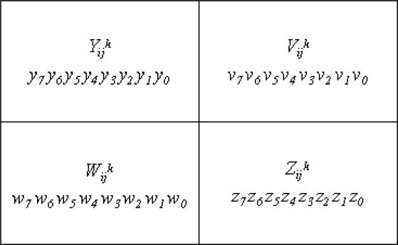
FIGURE 16.1
The ij-th block of the k-th cover.
Here, the binary representations of the pixels and , are (y1 y2 …y8), (v1 v2 …v8), (w1 w2…w8) and (z1 z2…z8), respectively. The steps in this scheme are as follows.
Step 1: Set the modulus p used in the polynomial in 16.1 to 251. If the pixel Iij ≥ 250, it is directly truncated to 250. Apparently, this operation can distort the secret image.
Step 2: Take the pixel Iij· as the coefficient c0 and choose k − 1 integers as other coefficients c1, c2,…,ck−1 randomly to construct a polynomial in Equation 16.1. Then takes the pixel value for 1 ≤ k ≤ n as the input x of the polynomial to compute the shared pixel , where (s1 s2…s8) means eight bits of the shared pixel .
Step 3: Embed the shared pixel into the block by replacing the eight bits v7 v8, w6 w7 w8 and z6 z7 z8 with s1 s2…s8 as shown in Figure 16.2.
Step 4: Generate a check bit b according to parity check policy to achieve the authentication capability shown in Figure 16.2.
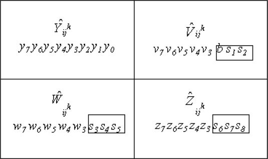
FIGURE 16.2
The block of the k-th stego-image in Lin-Tsai’s scheme.
Unfortunately, in Lin-Tsai’s scheme, the parity bit of the upper-right pixel shown in Figure 16.2 is chosen to make this pixel an even or odd parity as a binary parity sequence. Dishonest participants can derive the parity information from their own stego-images, and thus can easily and maliciously counterfeit a stego-image. For instance, assume that the upper-right pixel . A dishonest participant can modify it to (11011 010), which still meets the odd parity, but the 8-bit input of (k-1)-degree polynomial becomes changed. Thus, it successfully passes authentication but the (k-1)-degree polynomial cannot be obtained. In addition, the dishonest participant can also modify three other pixels, and , to change the input and output of (k-1)-degree polynomial without influencing the upper-right pixel , thus passing authentication. Therefore, their scheme has a weak authentication process, which may allow a fake stego-image to pass the authentication check quite easily.
16.2.2 Yang et al.’s Scheme
To overcome the weaknesses in Lin-Tsai’s scheme, Yang et al. [28] proposed an improved version in 2007. In Yang et al.’s scheme, the modulus value p is set to the Galois Field GF(28), that is, p = g(x) = x8 + x4 + x3 + x1 + x0. This approach allows the acquisition of a secret image without distortion.
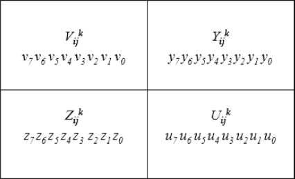
FIGURE 16.3
The cover blocks used in Yang et al.’s scheme.
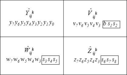
FIGURE 16.4
The block of a stego-image in Yang et al.’s scheme.
In Yang et al’s scheme, let the pixel Iij of the secret image be used to produce the n shared pixels , to be embedded into the cover blocks , where each cover block is represented as for 1 ≤ k ≤ n as shown in Figure 16.3. Pixel Iij of the secret image is first embedded into the coefficient c0 to construct a polynomial as shown in Equation 16.1. Next, the shared pixel is computed by taking the pixel value of the corresponding cover image block as the input x of the polynomial shown in Equation 16.1. Let the binary representation of the shared pixel be (s1 s2…s8). Hence, the shared pixel is embedded into its corresponding cover image block by replacing the eight bits v1 v0 y1 y0 z1 z0 u1 u0 with s1 s2 …s8, and at the same time, the bits z3 z2 of pixel are replaced by v1v0 of pixel in order to keep the complete pixel value for recovering the corresponding secret pixel as shown in Figure 16.4.
However, Yang et al.’s scheme cannot avoid the fact that four least significant bits (LSBs) of the pixel value in each block must be modified. Such modification may make the stego-images different from the cover images visually and the risk of being observed by attackers is increased.
To further improve Lin-Tsai’s authentication ability, Yang et al. used the hash-based message authentication code (HMAC) in Equation 16.2.
where id is the block ID; is 31 bits except the check bit b; H( ) and k denote a one-way hash function and the secret key, respectively. Next, as shown in Equation 16.3, the 160-bit HMAC output and executes the XOR operation to obtain the authentication bit b.
However, the average probability of detecting any malicious modification is just 50% because of the characteristic of the parity check itself. In other words, the fake stego-images still have a very high probability of being authenticated successfully.
16.2.3 Chang et al.’s Scheme
In 2008, Chang et al. proposed an enhanced secret sharing scheme based on Lin-Tsai’s scheme and Yang et al.’s scheme. They used the concept of Thien and Lin’s secret image sharing [23] to ensure that no distortion is introduced into the secret image and applied the concept of the Chinese Remainder Theorem (CRT) to improve authentication ability. As a result, their scheme can achieve high authentication ability. The flowchart of Chang et al.’s scheme [9] is shown in Figure 16.5.
Four check bits p1, p2, p3, p4 can be calculated and embedded into the stego-block (shown in Figure 16.5). The details are shown in the steps below.
Step 1: The residues set of the block in Figure 16.6 is determined.
;
;
;
;
;
.

FIGURE 433.16
The block of a stego-image in Chang et al.’s scheme.
Step 2: Decide six moduli that are pairwise relatively prime , and , where each modulus , for 1 ≤ a ≤ 6, is the prime number greater than .
Step 3: Calculate the integer by Equation 16.4. Suppose that the binary representation of the is (y1y2…ye). Note that the number of binary bits of has to be a multiple of 4.
Step 4: Four interim authentication bits a1, a2, a3, and a4 are computed by Equation 16.5.
Step 5: Denote b1, b2, b3, and b4 as the current four watermark bits; four check bits p1, p2, p3, and p4 can be computed by Equation 16.6.
Step 6: Replace the four LSBs x0v0w0z0 with the computed check bits p1 p2 p3 p4 as presented in Figure 16.6.
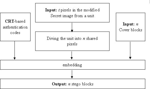
FIGURE 434.16
The flowchart of Chang et al.’s scheme.
16.3 Adopted Techniques in the Proposed Scheme
To give sufficient background knowledge, this section briefly introduces the related techniques adopted in our proposed scheme, including error diffusion, interpolation, canny edge detector, and edge lookup inverse halftoning as well as the Shamir scheme for secret sharing, respectively.
16.3.1 Error Diffusion Technique
The error diffusion technique is typically used to convert a multiple-level color image into a two-level color image. There are many kinds of idiographic error diffusion strategies. The common concept behind diffusion is the diffusion of errors to neighboring pixels; in this way, no image luminance is lost. The diffused image generated based on an error diffusion strategy is called an error filter. Each error filter has a set of kernel weights. Assume that GI(x,y) is the value of a pixel in position (x,y) in a grayscale secret image. Figure 16.7 is a flowchart of the error diffusion technique.
In the proposed scheme, the Floyd and Steinberg error diffusion strategy is adopted and the kernel weights are , as shown in Figure 16.8.
After the quantization procedure, a pixel GI(x,y) at position (x,y) in grayscale image GI becomes HI(x,y) and has a value of either 0 or 255. During the quantization procedure, a threshold TH is used to determine HI(x,y) according to Equation 16.7 and the quantization error is determined by Equation (5.8).
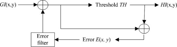
FIGURE 435.16
Error diffusion architecture.
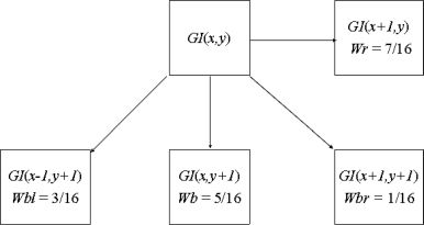
FIGURE 16.8
The kernel weights of Floyd and Steinberg’s error filter.
Next, error E(x,y) is diffused over four neighboring pixels, GI(x, y+1), GI(x +1, y-1), GI(x + 1, y), and GI(x + 1, y+1), according to Equation 16.9 and the kernel weights (denoted as W) of the error filter are shown in Figure 16.8.
where i, j ∈ {0,1}, ·
Based on Figure 16.8 and Equation 16.9, we can see that when pixels are on the border of the grayscale image, special cases occur. The four kinds of pixels listed below should be considered in distinguishing these cases.
Case 1: The pixels located at (x, 1), where x =1, 2,…, H-1.
Case 2: The pixels located at (H, y), where y =1, 2,…, W-1.
Case 3: The pixels located at (x, W), where x =1, 2,…, H-1.
Case 4: The pixel located at (H, W).
The positions of all four kinds of pixels are represented in Figure 16.9, with the white squares showing the positions of the pixels located at the border of an image. To deal with these special cases, we adopt a special skill, called “excursion” in the procedure, as shown in Figure 16.10.
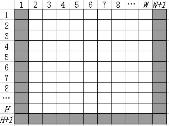
FIGURE 16.9
The positions of pixels located at the border in an image.
When applied to these pixels, Floyd and Steinberg’s error filter is slightly modified to ignore the nonexistent pixels because the number of these pixels is small compared with the total number of pixels in the whole image. To give a clearer explanation, the following paragraphs give one instance for each case.
At first, set E(1, 1) = 0. For case 1, the pixels at position (x, 1), where x = 1, 2,…, H-1 are considered. We take the pixel at position (1, 1) for example. The value of HI(1, 1) is determined by Equation 16.7. However, there is no pixel at position (2, 0) corresponding to GI(x+1, y-1). Thus, the neighboring pixels that accepted error diffusion are shown in Figure 16.11 for Case 1.
For Case 2, we take the pixel at position (H, 1) for example. The pixel at position (H, 1) is called GI(H, 1) and has an error value of E(H, 1). However, there are no pixels at positions (H+1, 0), (H+1, 1), and (H+1, 2) corresponding to GI(x+1, y-1), GI(x+1, y), and GI(x+1, y+1). Thus, the neighboring pixels that accepted error diffusion are shown in Figure 16.12 for Case 2.

FIGURE 16.10
The “excursion” skill.
For Case 3, we take the pixel at position (1, W) for example. There are no pixels at positions (1, W+1) and (2, W+1) corresponding to GI(x, y+1) and GI(x+1, y+1). Thus, the neighboring pixels that accepted error diffusion are shown in Figure 16.13 for Case 3.
And last, for Case 4, the pixel GI(H, W) at position (H, W), there are no pixels at positions (H, W+1), (H+1, W-1), (H+1, W), and (H+1, W+1) corresponding to GI(x, y+1), GI(x+1, y-1), GI(x+1, y), and GI(x+1, y+1). Thus, there are no neighboring pixels that accepted error diffusion for this case.
We next describe how to use the Floyd and Steinberg error diffusion strategy to transform a gray-scale image into a binary image. The detailed steps are set forth as follows:
Input: A gray-scale secret image GI sized H × W.
Output: A binary image HI sized H × W.
Step 1: Set a threshold TH = 127
Step 2: for i=1 H, j=1: W

FIGURE 438.16
The neighboring pixels that accepted error diffusion for Case 1.

FIGURE 16.12
The neighboring pixels that accepted error diffusion for Case 2.
Loop: if (i = 1) or i = H + 2)|(j = 1) or (j= W+2) → EGI(i,j) = 0; else EGI(i, j) = GI(i − 1,j − 1);
Step 3: for i = 2:H + 1, j = 2: W +1
Loop: if EGI(i, j) ≥ TH → EHI(i,j) = 255;
else EHI(i,j) = 0;
E(i,j) = EGI(i,j)-EHI(i,j);
EGI(i,j + 1) = EGI(i,j + 1) +E(i, j) × Wr; EGI(i + 1,j = EGI(i,j + 1) +E(i, j) × Wb;
EGI(i + 1,j + 1) = EGI(i + 1,j + 1) +E(i, j) × Wb;
EGI(i + 1,j - 1) = EGI(i + 1,j - 1) + E(i, j) × Wbl;
Step 4: for i = 1: H, j = 1:W
HI(i,j) = EHI(i + 1, j + 1).

FIGURE 439.16
The neighboring pixels that accepted error diffusion for Case 3.
16.3.2 Interpolation Technique
In computer computations, a discrete number system rather than a real number system is applied due to the limitations of machine representation. Therefore, a continuous signal must be sampled for computer storage and calculation. However, sampling is always destructive to the original information and new samples often must be reselected when the sampling scale is changed. Let us denote R as a real signal performed in the real number system as shown in Figure 16.14(a); denote D as the digital signal created by R, which is performed in the discrete number system shown in Figure 16.14 (b). The digital signal D′ shown in Figure 16.14(c) is generated by sampling digital signal D.

FIGURE 16.14
Example of sampling an image: (a) Real signal R; (b) Sampled signal D of R; (c) Sampled signal D′ of D.
Figure 16.14 shows that the re-sampled signal D′ can be easily retrieved when the real signal R is always available. However, the original signal is usually discarded after receiving the digital signal D. As a result, the resampled signal D′ must be created from the former signal D. Interpolation is a classical solution for calculating the new samples from another digital signal. Take bilinear interpolation for example. A new sample in signal D′ is expected to be an average value of the two neighboring original samples in D. Assuming that (x, f(x)) and (y, f(y)) are two neighboring samples in D, we can calculate a new sample (z, f (z)) in D′ according to Equation 16.10.
16.3.3 Canny Edge Detector
Edge detection is a kind of commonly used technique in image processing. The areas in an image with strong intensity contrasting from one pixel to the next are called edges. The purpose of edge detection is filtering out useless information in an image and significantly reducing the amount of data, while preserving the important structural properties.
Since the pioneering work by Roberts in 1965 [19], a mass of schemes have been developed for detecting edges. The Canny edge detection algorithm is known to many as the optimal edge detector proposed by J. Canny in 1986 [12], which finds edges by looking for local maxima of the gradient of the input image. The gradient is calculated using the derivative of a Gaussian filter. The Canny edge detector contains several adjustable parameters, listed as follows, which can affect the computation time and effectiveness of the algorithm itself. The first parameter is the size of the Gaussian filter, the smoothing filter used in the first stage, which directly affects the results of the Canny detection algorithm. Generally, smaller filters cause less blurring, and allow detection of small, sharp lines. On the contrary, larger filters cause more blurring, smearing out the value of a given pixel over a larger area of the image. Two thresholds are the other parameters. Actually, a too high threshold may make missing important information. On the other hand, a threshold set too low will falsely identify irrelevant information as important. Therewith, the detection would be more likely to be fooled by noise. The Canny edge detection method uses two thresholds, to detect strong and weak edges, and includes the weak edges in the output only if they are connected to strong edges.
The Canny edge detector works in a multistage process. First of all, the image is smoothed by Gaussian convolution. Afterwards, to highlight regions of the image with high first spatial derivatives, a simple 2-D first derivative operator is applied to the smoothed image and edges give rise to ridges in the gradient magnitude image. Then, the algorithm tracks along the top of these ridges and sets to zero all pixels that are not actually on the ridge top so as to give a thin line in the output, a process known as nonmaximal suppression. The tracking process exhibits hysteresis controlled by two thresholds, denoted by T1 and T2, where T1 > T2. Tracking can only begin at a point on a ridge higher than T1 and then continues in both directions out from that point until the height of the ridge falls below T2 . The Canny edge detector is more likely to detect true weak edges and less likely than the others to be fooled by noise.
16.3.4 Edge Lookup Inverse Halftoning Technique
The inverse halftoning technique is used to reconstruct a gray-scale image from an input halftone image. Based on the lookup table (LUT) [10,16] technique, in 2005 Chung and Wu [11] proposed a new edge-based lookup table (LUT) scheme that improves the quality of the reconstructed grayscale image. In the following paragraphs we call Chung and Wu’s scheme ELUT for short. The ELUT scheme first applies the LUT-based inverse halftoning scheme as a preprocessing step to transform the input halftone image to a base grayscale image, and then the edges are extracted and classified from the base grayscale image. According to these classified edges, a novel edge-based LUT is built up to reconstruct the grayscale image, i.e., the ELUT scheme. Figure 16.15 is a flowchart of Chung and Wu’s ELUT scheme.

FIGURE 16.15
The flowchart of Chung and Wu’s ELUT scheme.
Input: A set of n training image pairs (GIi, HIi), where GIi and HIi are denoted as the i-th grayscale image and its corresponding halftone image, respectively.
Step 1: Generate the lookup table (LUT) by using the five substeps that follow. An array LUT[ ] is used to map the given halftone image to the corresponding grayscale image.
For initialization, i = 1, LUT[k] = 0, where 0 ≤ k ≤ 216 − 1.
Divide images double HIi and GIi into overlapping 4 × 4 blocks and denote them as BHij and BGij. In other words, BHij and BGij are the j-th halftone block of halftone image HIi and the j-th grayscale block of grayscale image GIi, respectively.
Calculate index k for each halftone block BHij and update the value of the intermediate LUT[k] by using Equation 16.10. Here, BGij(3, 3) is a representative pixel for each grayscale block.
i = i + 1. If i ≤ n, go to Step b. Otherwise, compute and archive the final LUT[]. N[k] is another array used to store the number of halftone blocks that obtain the same index value k.
For 0 ≤ k ≤ 216 − 1, .
Step 2: Replace the element BHij(3, 3) in every block BHij by LUT[k], where k is the index value of block BHij calculated in Step c. When the replacement procedure is finished, retrieve the grayscale image with pixel values corresponding to LUT[k].
Step 3: After applying Step 2 to a set of n training images in succession, a set of reconstructed grayscale images called , i = 1, 2,…, n, can be retrieved. Adopt Canny’s edge detector to each reconstructed grayscale image to generate an edge map EMi, for i =1, 2,…, n. Each edge map EMi consists of a set of 4 × 4 blocks. Therefore, the j-th block of the edge map EMi is denoted as BEij. By combining the lookup table LUT generation procedure described in Step 1 with a set of edge maps EMi, an edge-based LUT, called an ELUT, is generated. Note that in this step, we call the edge map EM. The order of the edge pattern of the ij-th block is denoted as BEij. The index value for ij-th block is Iij for 0 ≤ k ≤ 216 − 1. Finally, the mean grayscale value can be derived from ELUT[Iij, BEij], where 0 ≤ EMij ≤ 38 based on the number of edge patterns reported by Chung and Wu [11]. In Chung and Wu’s scheme, the value of (3, 3) is determinate as Equation 16.12.
Step 4: Input a halftone image HI, which will be converted to the grayscale image GI′ . The detailed procedure is shown in Figure 16.16.
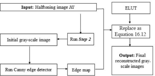
FIGURE 16.16
Procedure for generating final grayscale image in Step 4.
16.3.5 Shamir Scheme for Secret Sharing
The proposed scheme for secret image sharing is based on the (k,n)-threshold secret sharing scheme proposed by Shamir (1979) [20]. In this section we describe how to use the Shamir scheme to generate secret sharing. In the following steps we use the (k-1)-degree polynomial shown in Equation 16.16 to generate n shares for a group of n secret sharing participants from a secret integer value s for the threshold k.
where i = 1, 2,… , n.
Step 1: Select the number k, k ≤ n.
Step 2: Choose the (k-1) integers a1, a2, ak-1 randomly.
Step 3: For the i-th secret sharing participant, choose a value of xi freely, i = 1, 2,…, n. Note that all xi must be distinct from one another.
Step 4: For each chosen xi, compute the corresponding F(xi) by using Equation 16.13.
Step 5: Deliver each pair of (xi, F(xi)) as a secret share to each participant.
In this secret sharing process, the values of ai, i = 1, 2, … , k − 1, need not be kept after all secret shares are generated. As well as the secret value s, each αi can be recovered from the n secret shares in the secret recovery steps listed below.
Step 1: Collect at least k secret shares from the n ones to form a system of equations as shown in Equation 16.13. Note that the xi and F(xi) in Equation 16.13 with i =1, 2, … , k can all be extracted from the k secret shares.
Step 2: Use a polynomial interpolation technique, e.g., Lagrange scheme, to solve s and ai, i = 1, 2, … , k − 1. Reconstruct the (k − 1)-degree polynomial F(x) described by Equation 16.14.
Step 3: Compute the solution for the secret value s by Equation 16.15.
16.4 Proposed Scheme
Following on the details described in the previous discussions, this section presents a detailed and complete description of the proposed scheme. In our scheme, a halftone image HI is created from the grayscale secret image GI, sized H × W with 8 bits per pixel, by using an error diffusion technique called EDT. The transmitted stego-image is called SI and the reconstructed grayscale secret image is called GI′. The proposed scheme includes two procedures: the first is the sharing and embedding phase, and the second is the reconstruction and verifying phase. General flowcharts of the phases of our scheme appear in Figure 16.17 and Figure 16.18.
16.4.1 Sharing and Embedding Phase
A detailed algorithm for the sharing and embedding phase is described in this section.
Input: The secret grayscale image GI and cover image CI.
Output: Stego-image SI.
Step 1: Apply the error diffusion technique (EDT) to the grayscale image GI to retrieve a halftone image HI Obviously, the width and height of HI are W and H. Moreover, each pixel in halftone image HI contains only 1 bit.

FIGURE 446.16
The flowchart of the work by the sender.
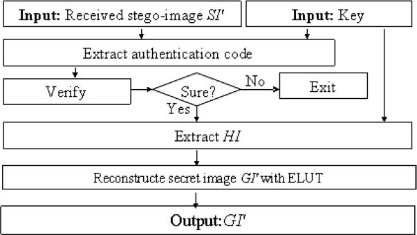
FIGURE 16.18
The flowchart of the work by the recipient.
Step 2: Divide halftone image HI into Z nonoverlapping 6-bit blocks, . HIz (z = 1,2,…,Z) is the z-th block of HI and the value of HIz, is denoted as Pz illustrated in Figure 16.19.

FIGURE 16.19
The z-th block of GI and the corresponding HIz, Pz.
Step 3: This is the basic process for secret image sharing with Pz as the secret, z = 1, 2, … Z, . This procedure contains five substeps, which are performed as follows.
Take the value Xi formed from 2-MSBs (Most Significant Bits) of the four pixels of each cover CBi as the value x specified in Equation 16.16, i = 1, 2 …, n, as shown in Figure 16.20, Xi = (c7c6d7d6g7g6h7h6)D.
Take the secret Pz as the value s specified in Equation 16.16.
With a random number generator, generate a set of k − 1 integers a1, a2, ak−1 in Equation 16.16, where k ≤ n.
For each Xi, compute the corresponding value of F(Xi) by Equation 16.16 to form a secret share (Xi, F(Xi)) for each participant in the secret sharing group, F(Xi) = f5 f4 f3 f2 f1 f0.
Hide the six data bits of F(Xi) in the Least Significant Bits of the four pixels Ci, Di, Gi, and Hi of the corresponding cover block C Bi as shown in Figure 16.21.

FIGURE 448.16
The four pixels of each cover block CBi.
Step 4: To prevent illicit attempts, a simple authentication ability is added here. Compute check bits pi by using Equation 16.17 and embed pi into the remaining LSBs of Ci, Di, Gi, Hi from the same cover block where i = 1, 2, …, t. Note that t is the total number of check bits, which is discretionary and could be decided by the sender according to authentication strength. For simplicity, we take t = 2 as an example to explain the procedure as shown in Figure 16.22. Figure 16.23 illustrates a flowchart of this phase.
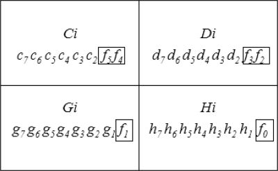
FIGURE 16.21
Hiding the six data bits of F(Xi).

FIGURE 16.22
Hiding the check bits p1, p2.
16.4.2 Reconstruction and Verifying Phase
This section describes the proposed secret recovery scheme and authentication scheme. Recall that after performing the secret sharing process for a group of n participants, each participant obtains one stego-image . The proposed process for stego-image authentication and secret image recovery is summarized in the following paragraphs.
Input: The random number generator used to generate integers a1, a2, …, ak−1 in Equation 16.16, the secret key t used for generating the check bits (e.g., t = 2), and a set of at least k stego-images , say m ones, with k ≤ m ≤ n, j =1, 2, …, m.
Output: A report of failure of secret reconstruction, or the recovered secret image GI′ if all the stego-images are authenticated as genuine.
Step 1: Use the random number generator to generate a1, a2, ak−1 in Equation 16.16.

FIGURE 450.16
The flowchart of Step 4.
Step 2: Divide each received stego-image , j = 1, 2,…, m, into 2 × 2 blocks and denote the four pixels in each block as , and as shown in Figure 16.24.
Step 3: For each stego-image from participant j, j ∈ {1, 2,…, m}, perform the following substeps for stego-image authentication.
t = 2, extract the 2-bit check bits from each block , as shown in Figure 16.25. .
Calculate the data for verification according to Equation 16.18.
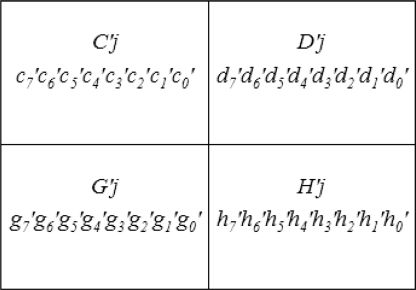
FIGURE 451.16
The four pixels of each stego block CB′j.If for each block, , then regard the stego-image as having passed authentication and continue; otherwise, decide that the stego-image has been tampered with.
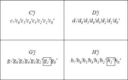
FIGURE 16.25
The 2-bit check bits carried in CB’z when t = 2.

FIGURE 452.16
The bits of Xi and F(Xi) carried in the stego block.
Step 4: If m′ stego-images have passed authentication in Step 3, and m′ ≥ k, then continue. For each collected stego-image ; otherwise, stop the program and report failure of the secret recovery step.
Step 5: For each z =1, 2, …, Z, , perform the following sub-steps to recover the secret data Pz.
For each , extract the 2 most significant bits (MSBs) of the four pixels of each cover as the value Xi specified in Equation 16.16, ; extract the data bits of F(Xi) from the LSBs of pixels , and , as shown in Figure 16.26, as a value of F(Xi) appearing in Equation 16.16.
By using the scheme described in Section 16.3.5, compute the corresponding value of y as the value Pz.
For each z = 1, 2, …, Z, , perform last steps to obtain all of the Pz for the blocks of halftone image HI of the secret image GI.
Step 6: Apply the edge- and LUT-based inverse halftoning algorithm (ELUT, introduced in Section 16.3.4) to the halftone image HI to retrieve the gray-scale image GI′, i.e., the secret image.
16.5 Experimental Results
The feasibility of the proposed scheme was confirmed by the experimental results discussed in this section. We conducted three experiments, one to estimate the visual quality of the stego-images; the second to estimate the visual quality of the reconstructed secret images; and the last to evaluate the capability of identifying the tampered region. The test images shown in Figure 16.27 are four grayscale images ” Jet-F16” “Baboon”, “Lena”, and “Pepper”.
For our experiments, we chose the peak-signal-to-noise ratio (PSNR) as the criterion to measure the visual quality of the grayscale images, which is defined in Equation 16.19 and Equation 16.20.
H and W is the height and width of the images P and P′ respectively. Phw and are the corresponding pixel values, and MSE is the mean-square-error between the two images.
In the first experiment, to compare the visual quality (i.e., PSNRs) between the cover images and the corresponding stego-images in Lin-Tsai’s scheme, Yang et al.’s scheme, Chang et al.’s scheme, and ours, we took the image ” Jet-F16” as the secret image and the images “Lena”, “Pepper,” and “Baboon” as the cover images, as shown in Figure 16.27. Figure 16.28 demonstrates the experimental results. The PSNRs of different schemes reveal that the visual quality of the stego-images generated by our scheme is the best of the schemes compared in our experiments.
To evaluate the visual quality of the recovered gray-scale images, we compared the PSNRs of the reconstructed grayscale images and the original secret image in Figure 16.29. From Figure 16.29, we can see the PSNR of Jet-F16, which is extracted from “Lena”, “Baboon” and “Pepper”, is larger than 30 dB. It means that not only does the revealing function of our scheme work well but also that the visual quality of the secret grayscale image is acceptable.
In addition, storage space and stego-image transmission time are important issues in secret sharing. Consequently, the pixel expansion problem should be eliminated or minimized with any useful secret image sharing scheme. In other words, the size of the cover images used in the sharing algorithm should be no larger than that of their secret images. However, the cover images produced during previous research, which are based on a polynomial approach [9,15,28], are much larger than their secret images. The cover-to-secret image size ratios of the existing schemes and the proposed scheme are listed in Table 16.1 for comparison. From Table 16.1, we can see the cover size/secret size of our scheme is the smallest and the most satisfactory.
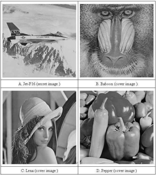
FIGURE 16.27
The test images.
To evaluate the capacity to identify a region of the secret image that has been tampered with, we compared the proposed scheme, Lin-Tsai’s scheme, Yang et al.’s scheme, and Chang et al.’s scheme using some manipulated stego-images that satisfy the parity check policy (shown in Figure 16.30).
Both Figure 16.30 and Table 16.2 show the experimental results for the various schemes. These results reveal that, among Lin-Tsai’s scheme, Yang et al.’s scheme, and the proposed scheme, our scheme provides the best authentication capability. In Lin-Tsai’s scheme, there is only one pixel for each block undergoing parity check. As a result, the authentication capability is not very good.
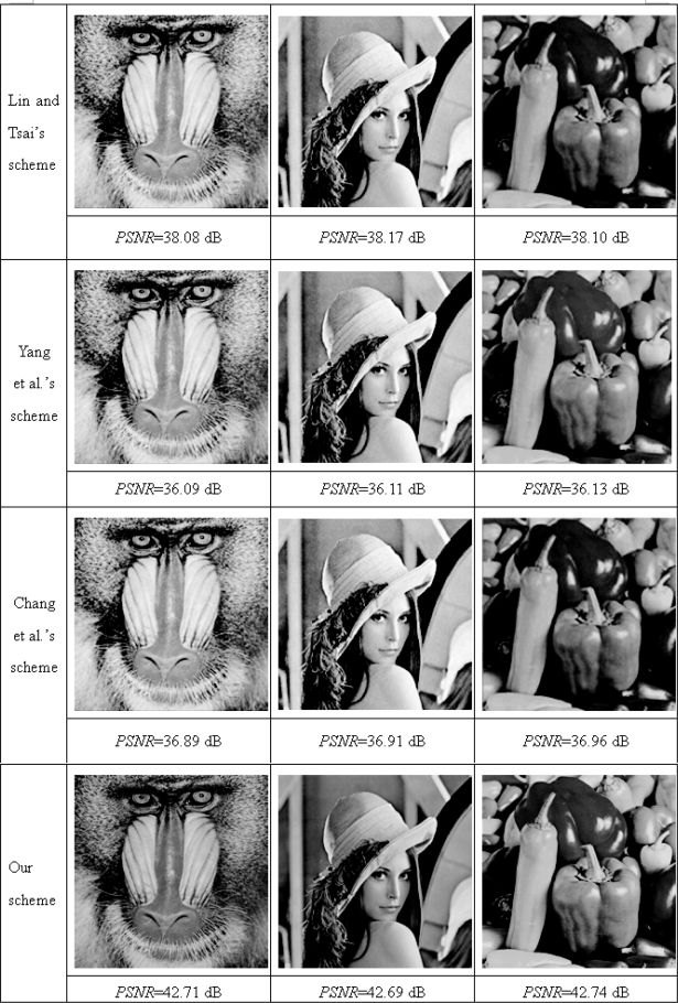
FIGURE 16.28
The experimental results for comparing the PSNR among the past work and ours.

FIGURE 456.16
The visual quality of the reconstructed grayscale image.
In Yang et al.’s scheme, four pixels of each block all undergo the procedure using a hash function. However, their final check bit is computed by using an XOR operation. So, their probability of successful authentication should remain at 50%. In our scheme, two check bits are adopted and the probability of successful authentication could be increased to 75%. On the other hand, compared with Chang et al.’s scheme, in which four check bits are adopted and authentication is implemented by using CRT (the Chinese Remainder Theorem), our proposed scheme has a lower detection ratio while maintaining lower computation complexity. However, because the set of shadows and the reconstructed secret image are generated through simple operations, no computational complexity or pixel expansion occurs with our scheme. Moreover, in practice, the nearly 80% detection ratio is sufficiently effective.

FIGURE 16.30
Three tampered stego-images.
Table 16.1 The cover-to-secret image size ratios of the existing schemes and the proposed scheme.
| Schemes | Cover size / secret size |
| Lin-Tsai’s scheme | 4 |
| Yang et al.’s scheme | 4 |
| Chang et al.’s scheme | 2 |
| Our scheme | 2/3 |
Table 16.2 The detection ratios of different schemes.
| Schemes | Detection ratios (DR) |
| Lin-Tsai’s scheme | 0% |
| Yang et al.’s scheme | 52% |
| Chang et al.’s scheme | 97% |
| Our scheme | 79% |
16.6 Conclusions
In this chapter, we propose a novel secret image sharing and authentication scheme in which the set of shadows and the reconstructed secret image are generated through simple operations, and no computational complexity or pixel expansion occur. The PSNR value of the reconstructed secret image is larger than 30 dB, and the visual quality of the reconstructed secret gray-scale image is acceptable.
Some research reported in the literature uses steganography as with Shamir’s secret sharing scheme [9,15,28]. However, with these approaches the cover images must be many times larger than their secret images. For a secret image of H × W pixels, for earlier schemes (introduced in Section 16.2), the cover image should be 2H × 2W pixels or 2H × W pixels in size. Such a restriction requires more storage capacity in the cover image and consumes a larger bandwidth during transmission. Experimental results confirm that each shadow generated by our scheme is six times smaller than the secret image. Moreover, the ratio of cover image size and secret image size is reduced to 2/3. This is the primary advantage of our scheme over past work. To compare visual quality between cover images and their corresponding stego-images with the earlier schemes and our proposed scheme, we used several images for our experiments. The experimental results are shown in Figure 16.29. The PSNRs of the various schemes compared demonstrate that the visual quality of the stego-images generated by our scheme is the best. This is the second advantage of our scheme over earlier work. The third advantage of our scheme over past work is that, based on the check bits embedded, our scheme provides an effective solution for verifying the reliability of the set of collected shadows in the context of low computational complexity. Furthermore, experiments confirm that our proposed scheme is suitable for real-time applications.
Bibliography
[1] A. Adhikari, and S. Sikdar, A New (2, n)-Visual Threshold Scheme for Color Images, INDOCRYPT 2003, Lecture Notes in Computer Science, Vol. 2904, pp. 148–161, 2003.
[2] G. R. Blakley, Safe guarding Cryptographic Keys, Proceedings of the National Computer Conference, American Federation of Information Processing Societies, Seoul, Korea, pp. 313–317, 1979.
[3] C. Blundo, A. D. Santis, and M. Naor, Visual Cryptography for Grey Level Images, Information Processing Letters, Vol. 27, pp. 255–259, 2000.
[4] C.C. Chang, C.C. Lin, C.H. Lin, and Y.H. Chen, A Novel Secret Image Sharing Scheme in Color Images Using Small Shadow Images, Information Sciences, Vol. 178, No. 11, pp. 2433–2447, 2008.
[5] Y. F. Chen, Y. K. Chan, C. C. Huang, et. al, A Multiple-Level Visual Secret-Sharing Scheme Without Image Size Expansion, Information Sciences, Vol. 177, No. 21, Part II, pp. 4696–4710, 2007.
[6] C. C. Chang, C. C. Lin, T. H. N. Le, and B. H. Le, A Probabilistic Visual Secret Sharing Scheme for Grayscale Images with Voting Strategy, Intelligent Information Hiding and Multimedia Signal Processing, pp. 184–188, 2008.
[7] C. C. Chang, C. C. Lin, T. H. N. Le, and B. H. Le, A New Probabilistic Visual Secret Sharing Scheme for Color Images, International Symposium on Electronic Commerce and Security, pp. 1305–1308, 2008.
[8] S. Cimato, R. De Prisco, and A. De Santis, Probabilistic Visual Cryptography Schemes, The Computer Journal, Vol. 49, No. 1, pp. 97–107, 2006.
[9] C.C. Chang, Y.P. Hsieh, and C.H. Lin, Sharing Secrets in Stego-images with Authentication, Pattern Recognition, Vol. 41, No. 10, pp. 3130–3137, 2008.
[10] P. C. Chang, C. S. Yu, and T. H. Lee, Hybrid LMS-MMS Inverse Halftoning Technique, IEEE Trans. Image Process., Vol. 10, No. 1, pp. 95–103, 2001.
[11] K. L. Chung and S. T. Wu, Inverse Halftoning Algorithm Using Edge-Based Lookup Table Approach, IEEE Trans. Image Process., Vol. 14, No. 10, pp. 1583–1589, 2005.
[12] J. Canny, A Computational Approach to Edge Detection, IEEE Trans. Pattern Analysis and Machine Intelligence., Vol. 8, No. 6, pp. 679–698, 1986.
[13] J. B. Feng, I. C. Lin, and Y. P. Chu, Halftone Image Resampling by Interpolation and Error-Diffusion, Proceedings of the 2nd International Conference on Ubiquitous Information Management and Communication, pp. 409–413, 2008.
[14] G. Horng, T. Chen, and D. Tasi, Cheating in Visual Cryptography, Designs, Codes and Cryptography, Vol. 38, pp. 219–236, 2006.
[15] C.C. Lin and W.H. Tsai, Secret Image Sharing with Steganography and Authentication, Journal of Systems and Software, Vol. 73, No. 3, pp. 405–414, 2004.
[16] M. Mese and P. P. Vaidyanathan, Look up Table (LUT) Scheme for Inverse Halftoning, IEEE Trans. Image Process., Vol. 10, No. 10, pp. 1566–1578, 2001.
[17] M. Naor and A. Shamir, Visual Cryptography, Advances in Cryptology - Eurocrypt’ 94, Lecture Notes in Computer Science, Vol. 950, pp. 1–12, 1995.
[18] R. D. Prisco and A. D. Santis, Cheating Immune (2, n)-Threshold Visual Secret Sharing, Lecture Notes in Computer Science, Vol. 4116, pp. 216–228, 2006.
[19] L. G. Roberts, Machine Perception of Three-Dimensional Solids, Optical and Electro-Optical Information Processing, pp. 159–197, 1965.
[20] A. Shamir, How to Share a Secret, Communications of ACM, Vol. 22, no. 11, pp. 612–613, 1979.
[21] S. J. Shyu, Efficient Visual Secret Sharing Scheme for Color Images, Pattern Recognition Letters, Vol. 39, No. 5, pp. 866–880, May 2006.
[22] A. Shiozaki, Digital Half-Toning by Error Diffusion with Perturbation, Electronics Letters, Vol. 32, No. 18, pp. 1655–1656, 1996.
[23] C.C. Thien and J.C. Lin, Secret Image Sharing, Computers and Graphics, Vol. 26, No. 5, pp. 765–770, 2002.
[24] C.C. Thien and J.C. Lin, An Image-Sharing Scheme with User-Friendly Shadow Images, IEEE Transactions on Circuits and Systems for Video Technology, Vol. 13, No. 12, pp. 1161–1169, 2003.
[25] R.Z. Wang and C.H. Su, Secret Image Sharing with smaller Shadow Images, Pattern Recognition Letters, Vol. 27, No. 6, pp. 551–555, 2006.
[26] A. Wang, L. Zhang, N. Ma, and X. Li, Two Secret Sharing Schemes Based on Boolean Operations, Pattern Recognition, Vol. 40, pp. 2776–2785, 2007.
[27] N. Yang, New Visual Secret Sharing Schemes Using Probabilistic Schemes, Pattern Recognition Letters, Vol. 25, No. 4, pp. 481–494, 2004.
[28] C.N. Yang, T.S. Chen, K.H. Yu, and C.C. Wang, Improvements of Image Sharing with Steganography and Authentication, Journal of Systems and Software, Vol. 80, No. 7, pp. 1070–1076, 2007.
[29] R. Zhao, J.J. Zhao, F. Dai, and F.Q. Zhao, A new Image Secret Sharing Scheme to Identify Cheaters, Computer Standards and Interfaces, Vol. 31, No. 1, pp. 252–257, 2009.