
CHAPTER 7
Active Directory Infrastructure
IN THIS CHAPTER
![]() Understanding AD DS Replication in Depth
Understanding AD DS Replication in Depth
![]() Understanding Active Directory Sites
Understanding Active Directory Sites
![]() Outlining Windows Server 2016 IPv6 Support
Outlining Windows Server 2016 IPv6 Support
![]() Detailing Real-World Replication Designs
Detailing Real-World Replication Designs
![]() Deploying Read-Only Domain Controllers
Deploying Read-Only Domain Controllers
In an ideal world, all areas of your network would be connected with high-capacity links, and every server would communicate with each other without latency or congestion. Alas, no real networks work this way, and traffic concerns must be considered in all but the smallest, single-server Active Directory Domain Services (AD DS) structure. Windows Server 2016 is built upon the AD DS replication capabilities introduced with the original Active Directory implementation in Windows 2000 Server with many new features and functionality added since then.
This chapter focuses on the definition of the components of Windows Server 2016 AD DS that make up its replication topology. It details design strategies for AD DS sites and provides real-world examples to illustrate the principles behind them. The concept of read-only domain controllers (RODCs) and how they can be deployed in remote sites is covered. In addition, Windows Server 2016 supports Internet Protocol version 6 (IPv6) and this is outlined and described in this chapter.
Understanding AD DS Replication in Depth
Windows Server 2016 AD DS replication technology is directly drawn from lessons learned from Windows 2000 through all previous versions through Windows Server 2012 R2. Read-only domain controllers (RODCs) can be created in remote sites to reduce replication and increase security. Replication compression can be disabled in well-connected sites, enabling designers to sacrifice bandwidth for processor utilization in domain controllers (DCs). In addition, concepts such as virtual DC cloning and DC promotion from media allow global catalog (GC) servers to be created from virtual hosts or media, which greatly increases DC placement flexibility. Other features, such as universal group caching on DCs, allow remote DCs to function as GC servers by caching frequently used universal group membership locally.
Many of these improvements to AD DS replication were introduced with Windows Server 2008 and, although there are few replication-specific improvements in Windows Server 2016, this latest version cements these new features and fixes design limitations that have thwarted replication plans in the past. Problems with replication design can potentially cripple a network, and it is, therefore, wise to put some serious thought into the proper layout and design of an effective replication scheme.
The Role of Replication in AD DS
All enterprise directory environments must include mechanisms to synchronize and update directory information across the entire directory structure. In Windows Server 2016 AD DS, this means that every DC must be updated with the most recent information so that users can log on, access resources, and interact with the directory accurately.
AD DS differs from many directory services implementations in that the replication of directory information is accomplished independently from the actual logical directory design. The concept of AD DS sites is completely independent from the logical structure of AD DS forests, trees, and domains. In fact, a single site in AD DS can actually host DCs from different domains or different trees within the same forest. This allows for the creation of a replication topology based on a wide-area network (WAN) structure, while the directory topology can mirror the organization’s structure.
Outlining Multimaster Topology Concepts
AD DS was specifically written to allow for the creation, modification, and deletion of directory information from multiple DCs. This concept, known as multimaster replication, allows no one DC to be authoritative. If any DCs go out of service, any one of the rest of the writable DCs can make changes to directory information. Those changes are then replicated across the domain infrastructure. Of course, there needs to be some level of control on this type of replication so that only the most recent changes take precedence. This type of control is realized in AD DS through the concept of update sequence numbers (USNs).
Explaining Update Sequence Numbers
All enterprise directory services implementations require a mechanism to handle the incremental storage of changes made to directory objects. In other words, whenever a password is changed, that information must be accurately passed to all DCs in the domain. This mechanism must also be able to apply only those changes that occurred at the most recent intervals.
Many directory services implementations relied on exact time synchronization on all DCs to synchronize information. However, keeping the clocks of multiple servers in sync has been proven to be extremely difficult, and even slight variations in time could affect replication results.
Thus was born the concept of the update sequence number (USN). AD DS uses USNs to provide for accurate application of directory changes. A USN is a 128-bit number that is maintained by each DC in AD DS (AD on Windows Server 2016 adopted the USN_RECORD_V4 structure. The USN is sequentially advanced upon each change that is made to the directory on that specific server. Each additional DC also contains a copy of the last-known USN from its peers. Updates are subsequently made to be more straightforward. For example, when requesting a replication update from Server2, Server1 references its internal table for the most recent USN that it received from Server2 and requests only those changes that were made since that specific number. The simplicity of this design also ensures accuracy of replication across the domain environment.
The integrity of replication is ensured with USNs because the USN number is updated only upon confirmation that the change has been written to the specific DC. This way, if a server failure interrupts the replication cycle, the server in question will still seek an update based on its USN number, ensuring the integrity of the transaction.
Resolving Replication Collisions
The concept of USNs does not completely eliminate the role of proper time synchronization in AD DS. It is still important to maintain accurate time across a domain environment because of the possibility of replication collisions. A replication collision is an inaccuracy in replicated information that takes place because of changes that are enacted on the same object, but before that change has been replicated to all DCs. For example, if an administrator resets a user’s password on Server1, and another administrator resets the same user’s password on Server2 before Server1 has had a chance to replicate that change, a replication collision will occur. Replication collisions are resolved through the use of property version numbers.
Applying Property Version Numbers
Property version numbers are applied as an attribute to all objects within AD DS. These numbers are sequentially updated and time-stamped whenever a change is made to that object. If a replication collision occurs, the property version number with the latest time stamp will be enacted, and the older change will be discarded. In the example from the preceding section, the password change with the latest time stamp will be applied to the user.
This concept subsequently requires accurate time synchronization to be a priority for an AD DS domain—although it is not as critical as in other directory services implementations that rely on it for all replication activity.
Time is an important aspect in AD DS. Kerberos is the native authentication mechanism used by Windows AD DS and bases its ticketing system on an accurate time source. If two machines in the same domain differ by more than five minutes, authentication will break. Therefore, accurate time must be shared among domain members.
Windows Server 2016 uses the Windows Time Service and the domain hierarchy to maintain a consistent source of time among all the DCs throughout the domain.
One server, the primary domain controller (PDC) emulator, is responsible for getting accurate time from a manual trusted source, such as National Institute of Standards and Technology (NIST), time.windows.com, pool.ntp.org, http://www.iis.net or a GPS clock, http://www.usno.navy.mil/USNO/time. This trusted source is known as stratum 0. The PDC emulator is stratum 1. Stratum 2 goes to all other DCs in the same site as the PDC emulator. The bridgehead server in remote sites is stratum 3 and all other DCs in the same remote site are stratum 4.
Member computers will try to get time from the lowest stratum DC in their own site. If that DC is not serving time, they use the next highest stratum.
Domain computers always honor this system, which explains why the clock resets to the domain time automatically, even if you change the local clock. Time normally syncs at startup and every 45 minutes thereafter for three consecutive, successful times, and then the interval check period is increased to 8 hours.
It is important that administrators configure and test the manually configured external time source on the PDC emulator.
Establishing Connection Objects
Connection objects are automatically generated by the AD DS Knowledge Consistency Checker (KCC) to act as pathways for replication communication. They can be manually established, as well, and essentially provide a replication path between one DC and another. If, for example, an organization wants to have all replication pushed to a primary domain controller (PDC) before it is disseminated elsewhere, direct connection objects can be established between the two DCs.
Creating a connection object is a straightforward process. After one is created, Windows Server 2016 does not attempt to automatically generate a new one across the same route unless that connection object is deleted. To manually set a connection object to replicate between DCs, follow these steps:
1. From Server Manager, click Tools, Active Directory Sites and Services.
2. Expand SitesSitenameServersServernameNTDS Settings, where Servername is the source server for the connection object.
3. Right-click NTDS Settings and choose New Active Directory Domain Services Connection.
4. Select the target DC, and click OK.
5. Name the connection object, and click OK.
6. Right-click the newly created connection object, and select Properties to open a properties page for the object. You can then modify the connection object to fit any specific schedule, transport, and so on.
NOTE
The connection objects that appear as automatically generated were created by the KCC component of AD DS to provide for the most efficient replication pathways. You must, therefore, have a good reason to manually create these pathways because the automatically generated ones usually do the trick.
Understanding Replication Latency
Administrators who are not accustomed to AD DS replication topology might become confused when they make a change in AD and find that the change is not replicated immediately across their environment. For example, an administrator might reset a password on a user’s account, only to have that user complain that the new password does not immediately work. The reason for these types of discrepancies simply lies in the fact that not all AD changes are replicated immediately. This concept is known as replication latency. Because the overhead required in replicating change information to all DCs immediately is large, the default schedule for replication is not as often as might be desired. Replication of critical information can be forced through the following procedure:
1. From Server Manager, click Tools, Active Directory Sites, and Services.
2. Drill down to SitesSitenameServersServernameNTDS Settings, where Servername is the server that you are connected to and that the desired change should be replicated from.
3. Right-click each connection object and choose Replicate Now.
Alternatively, you can use PowerShell to force or manage replication. Microsoft has added a large number of PowerShell commands to this version of Windows Server, which enable you to get even more granular with replication, allowing you to synchronize a single object using the Sync-ADObject commandlet. For a full list of Active Directory PowerShell commandlets, type get-command–module ActiveDirectory at the PowerShell prompt (see Chapter 20, Automating Tasks Using PowerShell Scripting).
Another useful tool that can be used to force replication is the repadmin command-line tool. This tool is installed as part of a default Windows Server 2016 DC install. After it is installed, you can use repadmin to force replication for the entire directory, specific portions of the directory, or to sync DCs across site boundaries. If the bandwidth is available, a batch file can be effectively written to force replication between DCs, effectively making the directory quiescent.
The default replication schedule can be modified to fit the needs of your organization. For example, you might decide to change the default schedule of 180 minutes to a schedule as low as every 15 minutes. To make this change, follow these steps:
1. From the All apps button, click Windows Administration Tools, Active Directory Sites and Services.
2. Drill down to SitesSitename (if you have just created your domain, the site is most likely named “Default-First-Site-Name”).
3. Right-click NTDS Site Settings and choose Properties.
4. Click Change Schedule.
5. Set the Schedule to Four Times per Hour, as shown in Figure 7.1.
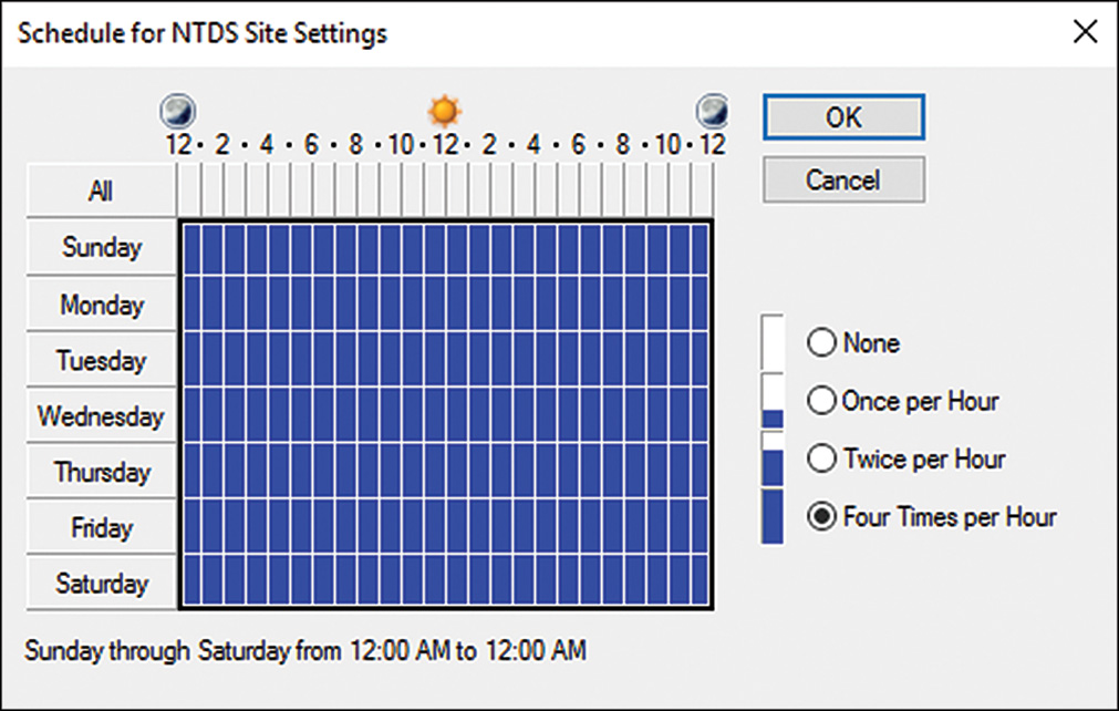
6. Click OK to save any schedule changes, and then click OK again to close the NTDS Site Settings Properties page.
Of course, changing this schedule comes with some caveats, namely watching for increased frequency of network bandwidth consumption. You should match the trade-off of your organization’s needs with the increased resource consumption levels required.
Understanding Active Directory Sites
The basic unit of AD DS replication is known as the site. Not to be confused with actual physical sites, the AD site is simply a group of highly connected computers and DCs. Each site is established to more effectively replicate directory information across the network. In a nutshell, DCs within a single site will, by default, replicate more often than those that exist in other sites. The concept of the site constitutes the centerpiece of replication design in AD DS.
Intrasite replication is approximately 15 seconds when the forest functional level is set to Windows Server 2008 or higher. The intrasite replication default is set to five minutes for Windows 2000 Server forest functional level.
Windows Server 2016 Site Functionality
Specific functionality that affects sites has evolved since the early days of Active Directory. Windows Server 2003 introduced numerous replication enhancements that directly affect the functionality of sites and allow for greater design flexibility with regard to site design. These changes continue to exist in Windows Server 2016. This functionality includes the following:
![]() Read-only domain controllers (RODCs) and read-only global catalogs (ROGCs)
Read-only domain controllers (RODCs) and read-only global catalogs (ROGCs)
![]() AD DS optionally installed on Server Core
AD DS optionally installed on Server Core
![]() GC universal group membership caching
GC universal group membership caching
![]() Media-based DC creation
Media-based DC creation
![]() Linked-value replication
Linked-value replication
![]() The KCC’s Intersite Topology Generator (ISTG) algorithm improvements
The KCC’s Intersite Topology Generator (ISTG) algorithm improvements
![]() No GC full synchronization with schema changes
No GC full synchronization with schema changes
![]() Ability to disable replication packet compression
Ability to disable replication packet compression
![]() Lingering object detection
Lingering object detection
![]() Deferred Index Creation
Deferred Index Creation
![]() Off-Premises Domain Join
Off-Premises Domain Join
These concepts are elaborated more fully in later sections of this chapter.
Associating Subnets with Sites
In most cases, a separate instance of a site in AD DS physically resides in a separate subnet for other sites. This idea stems from the fact that the site topology most often mimics, or should mimic, the physical network infrastructure of an environment.
In AD DS, sites are associated with their respective subnets to allow for the intelligent assignment of users to their respective DCs. For example, consider the design shown in Figure 7.2.

Server1 and Server2, both members of Site1, are both physically members of the 10.1.1.x subnet. Server3 and Server4 are both members of the 10.1.2.x subnet. Client1, which has a physical IP address of 10.1.2.145, will be automatically assigned Server3 and Server4 as its default DCs by AD DS because the subnets have been assigned to the sites in advance. Making this type of assignment is fairly straightforward. The following procedure details how to associate a subnet with a site. You can also create the subnet using the New-ADReplicationSubnet commandlet in PowerShell.
1. From Server Manager, click Tools, Active Directory Sites and Services.
2. Drill down to SitesSubnets.
3. Right-click Subnets and choose New Subnet.
4. Enter the network portion of the IP range that the site will encompass, such as what is shown in Figure 7.3. Select a site for the subnet and click OK.

Creating Site Links
By default, the creation of two sites in AD DS does not automatically create a connection linking the two sites. This type of functionality must be manually created, in the form of a site link.
A site link is essentially a type of connection that joins together two sites and allows for replication traffic to flow from one site to another. Multiple site links can be set up and should normally follow the WAN lines that your organization follows. Multiple site links also ensure redundancy so that if one link goes down, replication traffic follows the second link.
Creation of site links is another straightforward process, although you should establish in advance which type of traffic will be utilized by your site link: SMTP or IP (refer to the “Choosing SMTP or IP Replication” section).
Site link replication schedules can be modified to fit the existing requirements of your organization. If, for example, the WAN link is saturated during the day, a schedule can be established to replicate information at night. This functionality allows you to easily adjust site links to the needs of any WAN link.
With the assumption that a default IP site link is required, the following steps will create a simple site link to connect Site1 to Site2. In addition, the replication schedule will be modified to allow replication traffic to occur only from 6:00 p.m. to 6:00 a.m. at one-hour intervals:
1. From Server Manager, click Tools, Active Directory Sites and Services.
2. Drill down to SitesInter-Site TransportsIP.
3. Right-click IP and choose New Site Link to open a properties page similar to the one shown in Figure 7.4.
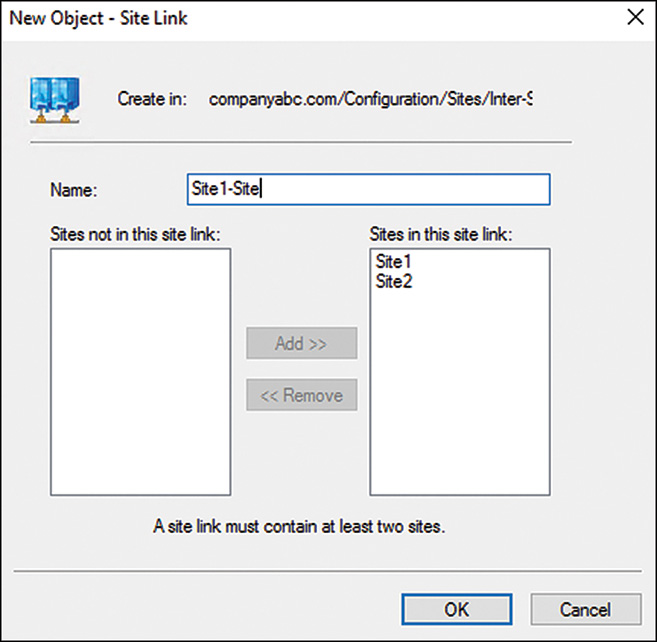
4. Give a name to the site link that will easily identify what it is. In our example, we named it Site1-Site2.
5. Ensure that the sites you want to connect are located in the Sites in This Site Link box.
6. Click OK to create the site link.
7. Right-click the newly created site link and choose Properties.
8. Click Change Schedule.
9. Select the appropriate time for replication to occur.
10. Click OK twice to save all settings to the site link.
Turning Off Site Link Bridging
By default, all site links are bridged, which means that all DCs in every site can communicate directly with any other DC through any of a series of site links. Such a bridge has the advantage of introducing redundancy into an environment; for example, if Site A has a link with Site B, and Site B is linked to Site C, servers in Site C can communicate directly with Site A.
Sometimes it is preferable to turn off this type of replication. For example, your organization might require that certain DCs never communicate directly with other DCs. In this case, site bridging can be turned off through the following procedure:
1. From Server Manager, click Tools, Active Directory Sites and Services.
2. Navigate to SitesInter-Site TransportsIP (or SMTP, if appropriate).
3. Right-click the IP (or SMTP) folder and choose Properties.
4. Uncheck the Bridge All Site Links check box.
5. Click OK to save the changes.
NOTE
Turning off site link bridging will effectively make your DC replication dependent on the explicit site links you have established.
Understanding the Knowledge Consistency Checker and the Intersite Topology Generator
Every DC contains a role called the Knowledge Consistency Checker (KCC) that automatically generates the most efficient replication topology at a default interval of every 15 minutes. The KCC creates connection objects that link DCs into a common replication topology. The KCC has two components: an intrasite KCC, which deals with replication within the site, and an Intersite Topology Generator (ISTG), which establishes connection objects between sites (only one DC in each site holds the ISTG role at any given time).
From Windows Server 2003 on, the Active Directory design team vastly improved the algorithm used by the ISTG, which resulted in a several-fold increase in the number of sites that can effectively be managed in AD DS. The number of sites that can be effectively managed in AD DS exceeds 5,000.
Determining Site Cost
An AD replication mechanism allows designers and administrators to establish preferred routes for replication to follow. This mechanism is known as site cost, and every site link in AD DS has a cost associated with it. The concept of site cost, which might be familiar to many administrators, follows a fairly simple formula. The lowest-cost site link becomes the preferred site link for communications to a site. Higher-cost site links are established mainly for redundancy or to reduce traffic on a specific segment. In this way, administrators can “shape” the flow of traffic between and among sites. Figure 7.5 illustrates a sample AD site structure that utilizes different costs on specific site links.

In this example, traffic between the Sendai and Fukuoka sites follow the Sendai-Tokyo site link because the cost of that site link is 15. However, if there is a problem with that connection or it is saturated, replication traffic will be routed through the Sendai-Morioka and then through the Morioka-Tokyo and Tokyo-Fukuoka site links because the total cost (all site link costs added together) for this route is 17. This type of situation illustrates the advantage of using multiple routes in an AD DS site topology.
Utilizing Preferred Site Link Bridgeheads
Often, it becomes necessary to segregate all outgoing or incoming intersite traffic to a single DC, thus controlling the flow of traffic and offloading the special processor requirements that are required for this functionality. This concept gave rise to preferred site link bridgeheads, DCs in a site that are specifically assigned to be the end or starting point of a site link. The preferred bridgehead servers will subsequently be the handler for all traffic for that specific site link.
Multiple site link bridgeheads can be easily defined in AD DS. The following example illustrates how this is accomplished. In these steps, Server2 is added as a preferred site link bridgehead for the site link named Site1-Site2:
1. From Server Manager, click Tools, Active Directory Sites and Services.
2. Drill down to SitesSitenameServersServername, where Servername is the server you want to establish as a bridgehead server.
3. Right-click Servername and choose Properties.
4. Select the transport for which this server will be made a bridgehead and click Add.
5. Click OK to save the settings.
Preferred bridgehead servers bring with them both advantages and disadvantages. The advantage of designating a preferred bridgehead server is that in an environment where DCs with weaker processors need to be excluded as designated site bridgeheads or when a DC holds an Operations Master (OM) role, especially that of the PDC emulator, having a designated preferred bridgehead server can allow for controlled communications to a specific bridgehead server.
However, the problem with selecting a preferred bridgehead server is that the preferred server designation prevents the KCC from failing over to other DCs in the same site if the preferred bridgehead server goes offline. Effectively, the preferred bridgehead servers must remain up as general AD redundancy is now focused at a sole server, not to any surviving server in a site.
Typically, organizations choose to not implement preferred bridgehead servers, and only implement them when they have a specific need to designate a server in a site as a preferred bridgehead server.
Deploying AD DS DCs on Server Core
Windows Server 2016 has an installation option called Server Core that allows the operating system to be deployed with only those services that are absolutely required for the role that the server holds. For DCs, this includes only those services that are needed for a DC to operate. Server Core is configured to run at a command prompt, without a graphical user interface (GUI) to further reduce the security profile of the box.
Deploying dedicated DCs using Server Core is ideal in many situations where security is a strong requirement. By doing so, only the necessary functionality is deployed, and no auxiliary services are required.
Planning Replication Topology
Network traffic patterns are an important consideration when implementing AD DS, and a firm understanding of the “pipes” that exist in an organization’s network is warranted. If all remote sites are connected by 30 Mb WAN links, for example, there will be fewer replication concerns than if network traffic passes through a slow link.
With this point in mind, mapping out network topology is one of the first steps in creating a functional and reliable replication topology.
Mapping Site Design into Network Design
Site structure in Windows Server 2016 is completely independent from the domain, tree, and forest structure of the directory. This type of flexibility allows domain designers to structure domain environments without needing to consider replication constrictions. Consequently, domain designers can focus solely on the replication topology when designing their site structure, enabling them to create the most efficient replication environment.
Essentially, a site diagram in Windows Server 2016 should look similar to a WAN diagram of your environment. In fact, site topology in AD DS was specifically designed to be flexible and adhere to normal WAN traffic and layout. This concept helps to define where to create sites, site links, and preferred site link bridgeheads.
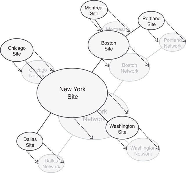
Figure 7.6 illustrates how a sample site structure in AD overlays easily onto a WAN diagram from the same organization. Consequently, it is a very good idea to involve the WAN personnel in a site design discussion. Because WAN environments also change in structure, WAN personnel will subsequently be more inclined to inform the operating system group of changes that could also affect the efficiency of your site design.
Establishing Sites
Each “island” of high connectivity should normally be broken into separate sites. This not only assists in DC replication, but also ensures that clients receive the closest DC and GC server to themselves.
If your DNS records are inaccurate for a site, clients could be potentially redirected to a DC or GC server other than the one that is closest to them. Consequently, it is important to ensure that all your sites listed in DNS contain the appropriate server host records. This concept is explained more thoroughly in Chapter 10, “DHCP, IPv6, and IPAM.”
Choosing Between One Site or Many Sites
In some cases, multiple LAN segments might be consolidated into a single site, given that the appropriate bandwidth exists between the two segments. This might be the case for a corporate campus, with various buildings that are associated with LAN “islands” but that are all joined by high-speed backbones. However, there might also be reasons to break these segments into sites themselves. Before the decision is made to consolidate sites or separate into individual sites, all factors must be taken into account.
Single-site design is simpler to configure and administer, but also introduces an increase in intersegment traffic because all computers in all buildings must traverse the network for domain authentication, lookups, and so on.
A multiple-site design addresses the problems of the intersegment traffic because all local client requests are handled by DCs or GC servers locally. However, the complexity of the environment is more significant and the resources required increase.
NOTE
It is no longer a firm recommendation that all sites contain at least one GC DC server. The introduction of the universal group caching capability and RODCs can reduce the number of GC servers in your environment and significantly reduce the amount of replication activity that occurs. This recommendation still stands, however, for sites with a local Exchange server because one or more local full GC servers are still critical for these environments.
The requirements of an organization with the resources available should be mapped to determine the best-case scenario for site design. Proper site layout helps to logically organize traffic, increase network responsiveness, and introduce redundancy into an environment.
Optimizing Subnet Site Associations
It is critical to establish the physical boundaries of your AD sites because this information utilizes the most efficient logon and directory requests from clients and helps to determine where new DCs should be located. Multiple subnets can be associated with a single site, and all potential subnets within an organization should be associated with their respective sites to realize the greatest benefit.
Determining Site Links and Site Link Costs
As previously mentioned, site links should normally be designed to overlay the WAN link structure of an organization. If multiple WAN routes exist throughout an organization, it is wise to establish multiple site links to correspond with those routes.
Organizations with a meshed WAN topology need not establish site links for every connection, however. Logically consolidating the potential traffic routes into a series of pathways is a more effective approach and helps to make your environment easier to understand and troubleshoot.
Choosing Replication Scheduling
Replication traffic can potentially consume all available bandwidth on small or saturated WAN links. By changing the site link replication schedule for off-hours, you can easily force this type of traffic to occur during times when the link is not utilized as heavily. Of course, the drawback to this approach is that changes made on one side of the site link would not be replicated until the replication schedule dictates. Weighing the needs of the WAN with the consistency needs of your directory is, therefore, important. Throttling the replication schedule is just another tool that can help to achieve these goals.
Choosing SMTP or IP Replication
By default, most connections between sites in AD DS utilize IP for replication because the default protocol used, Remote Procedure Call (RPC), is more efficient and faster. However, in some cases, it might be wiser to utilize SMTP-based replication. For example, if the physical links on which the replication traffic passes are not always on (or intermittent), Simple Mail Transport Protocol (SMTP) traffic might be more ideal because RPC has a much lower retry threshold.
A second common use for SMTP connections is in cases where replication needs to be encrypted so as to cross unsecured physical links, such as the Internet. SMTP can be encrypted through the use of a certificate authority (CA) so that an organization that requires replication across an unsecured connection can implement certificate-based encryption.
NOTE
SMTP replication cannot be used as the only method of replicating to a remote site. It can only be used as a supplemental replication transport because only certain aspects of domain replication are supported over SMTP. Subsequently, the use of SMTP replication as a transport is limited to scenarios where this form of replication is used in addition to RPC-based replication.
Windows Server 2016 Replication
The introduction of Windows 2000 provided a strong replication topology that was adaptive to multiple environments and allowed for efficient, site-based dissemination of directory information. Real-world experience with the product since the advent of AD has been incorporated into every version of the product since, and Windows Server 2016 is no exception. Replication enhancements in AD DS can help to increase the value of an organization’s investment in AD.
DC Promotion from Media
Windows Server 2016 allows for the creation of a DC directly from media such as a CD/DVD, USB drives, or tape. The upshot of this technique is that it is now possible to remotely build a DC or GC server across a slow WAN link by shipping the media to the remote site ahead of time, effectively eliminating the once common practice of building a DC in the central site and then shipping it to a remote site after the fact.
The concept behind the media-based GC/DC replication is straightforward. A current, running DC backs up the directory through a normal backup process. The backup files are then copied to a backup media, such as a CD/DVD, USB drive, or tape, and shipped off to the remote destination. Upon their arrival, the DC promotion process can be run, and Advanced mode can be chosen from the wizard. In the Advanced mode of the wizard, the dialog box shown in Figure 7.7 allows for DC promotion to be performed against a local media source.
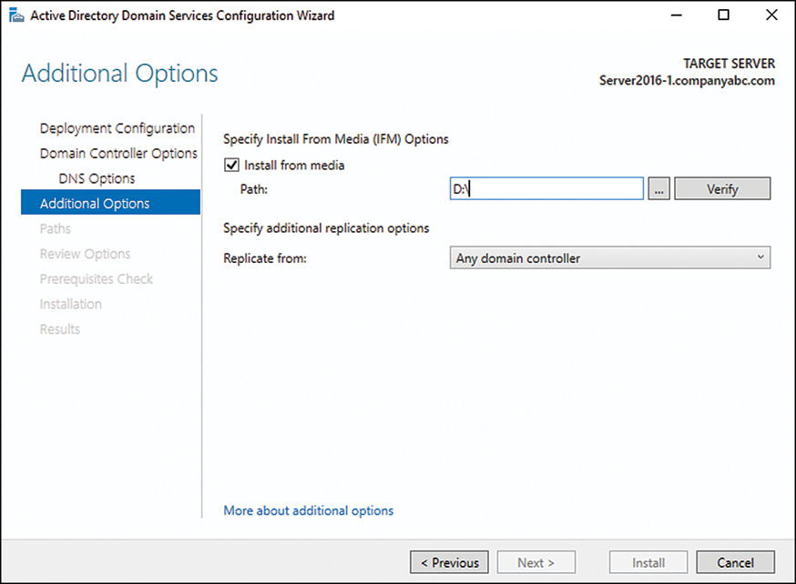
After the wizard restores the directory information from the backup, an incremental update of the changes made since the media was created will be performed. Because of this, there still needs to be network connectivity throughout the DC promotion process, although the amount of replication required is significantly less. Because some DC promotion operations across slow WAN links have been known to take days and even weeks, this concept can dramatically help to deploy remote DCs.
If the copy of the GC that has been backed up is older than the tombstone date for objects in the AD DS (by default, 60 days from when an object was last validated as being active), this type of DC promotion will fail. This built-in safety mechanism prevents the introduction of lingering objects and also ensures that the information is relatively up to date and no significant incremental replication is required.
Identifying Linked-Value Replication/Universal Group Membership Caching
Previously, all groups in AD DS had their membership listed as a multivalued attribute. This meant that any time the group membership was changed, the entire group membership needed to be re-replicated across the entire forest. Windows Server 2016 includes an incremental replication approach to these objects, known as linked-value replication. This approach significantly reduces replication traffic associated with AD DS.
Directly associated with this concept, Windows Server 2016 allows for the creation of DCs that cache universal group membership. This means that it is not necessary to place a GC server in each site. Any time a user utilizes a universal group; the membership of that group is cached on the local DC and is used when the next request comes for that group’s membership. This also lessens the replication traffic that would occur if a GC was placed in remote sites.
One of the main sources of replication traffic was discovered to be group membership queries—hence, the focus on fixing this problem. In older versions of Active Directory, every time a client logged on, the client’s universal group membership was queried, requiring a GC to be contacted. This significantly increased logon and query time for clients who did not have local GC servers. Consequently, many organizations stipulated that every site, no matter the size, must have a local GC server to ensure quick authentication and directory lookups. The downside of this was that replication across the directory was increased because every site received a copy of every item in the entire AD, even though only a small portion of those items was referenced by an average site.
Universal group caching solved this problem because only those groups that are commonly referenced by a site are stored locally, and requests for group replication are limited to the items in the cache. This helps to limit replication and keep domain logons speedy.
Universal group caching capability is established on a per-site basis as follows:
1. From Server Manager, click Tools, Active Directory Sites and Services.
2. Navigate to SitesSitename.
3. Right-click NTDS Site Settings and choose Properties.
4. Check the Enable Universal Group Membership Caching check box, as shown in Figure 7.8.
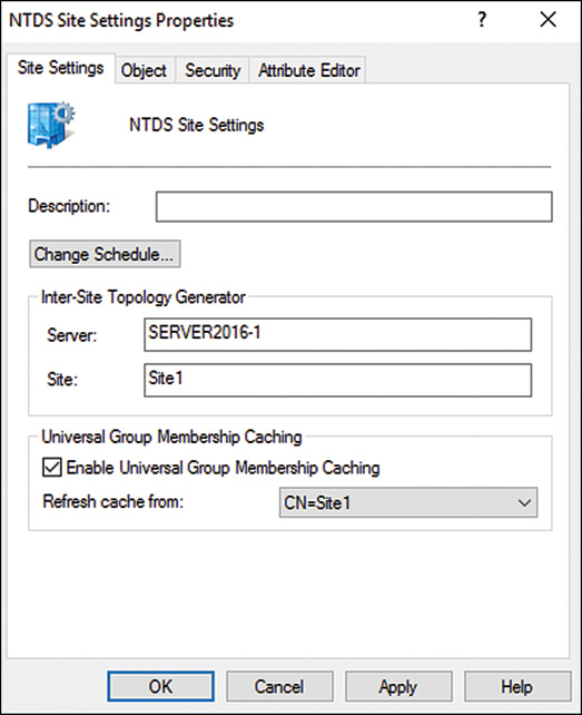
Optionally, you can specify which site to refresh the cache from.
5. Click OK to save the changes.
Removing Lingering Objects
Lingering objects, also known as zombies, are created when a DC is down for a period of time that is longer than the tombstone date for the deletion of items. When the DC is brought back online, it never receives the tombstone request and those objects always exist on the downed server. These objects could then be re-replicated to other DCs, arising from the dead as “zombies.” Windows Server 2016 has a mechanism for detecting lingering objects, isolating them, and marking them for cleanup.
Disabling Replication Compression
By default, intersite AD replication is compressed so as to reduce the bandwidth consumption required. The drawback to this technique is that extra CPU cycles are required on the DCs to properly compress and decompress this data. Windows Server 2016 allows designers the flexibility to turn off this compression, if an organization is short on processor time and long on bandwidth, so to speak.
Understanding How AD Avoids Full Synchronization of Global Catalog with Schema Changes
In the original version of Active Directory, any schema modifications forced a complete resynchronization of the GC with all DCs across an enterprise. This made it extremely ominous to institute any type of schema modifications because replication modifications would increase significantly following schema modifications. Windows Server 2003 and later AD DS environments do not have this limitation, however, and schema modifications are incrementally updated in the GC.
The Intersite Topology Generator Algorithm
The Intersite Topology Generator (ISTG) portion of the Knowledge Consistency Checker (KCC) allows AD environments to scale to site structures of up to 5,000 sites. Previous limitations to the Windows 2000 ISTG essentially kept AD implementations effectively limited to 1,000 sites. This feature is available only when all DCs in your AD DS environment are at least Windows Server 2008 systems and the forest functional level has been raised to Windows Server 2008 or higher levels. (Technically speaking, this was possible with Windows Server 2003, but as of 2016, Windows Server 2003 is no longer supported.)
Windows Server 2016 IPv6 Support
When the original structure of the Internet was taking shape, an addressing scheme was formulated to scale to a large number of hosts. From this thinking came the original design of the Internet Protocol, which included theoretical support for more than 4 billion addresses, or 2 ^ 32. The thinking at the time was that this would be more than enough addresses for all hosts on the Internet. This original design gave birth to the IP address structure that is common today, known as dotted-decimal format (such as 12.155.166.151). At the time, this address space filled the addressing needs of the Internet. However, it was quickly discovered that the range of addresses was inadequate, and stopgap measures such as Network Address Translation (NAT) were required to make more efficient use of the available addresses.
In addition to an inadequate supply of available addresses, the Internet Protocol version 4 (IPv4), as it is known, did not handle routing, IP Security (IPsec), and quality-of-service (QoS) support very efficiently. The need for a replacement to IPv4 was evident.
In the early 1990s, a new version of the Internet Protocol, known as Internet Protocol version 6 (IPv6), was formulated. This design had several functional advantages to IPv4, namely a much larger pool of addresses from which to choose by allowing for 2 ^ 128 theoretical IP addresses, or over 340 undecillion, which gives more than enough IP addresses for every square centimeter on the earth. This protocol is the future of Internet addressing, and it is vitally important that an operating system support it.
Windows Server 2016 comes with the latest version of IPv6 installed, and is fully supported as part of the operating system and enabled by default on all systems. It is subsequently important to better understand how IPv6 works in a Windows Server 2016 environment.
Defining the Structure of IPv6
To say that IPv6 is complicated is an understatement. Attempting to understand IPv4 has been difficult enough for network engineers; throw in hexadecimal 128-bit addresses and life becomes much more interesting. IPv6 has been around now for several years and yet many administrators still balk at the idea of managing and IPv6 network; however, at a minimum, the basics of IPv6 must be understood as future networks will use the protocol more and more as time goes by.
IPv6 was written to solve many of the problems that persist on the modern Internet today. The most notable areas that IPv6 improved upon are the following:
![]() Vastly improved address space—The differences between the available addresses from IPv4 to IPv6 are literally exponential. Without taking into account loss because of subnetting and other factors, IPv4 could support up to 4,294,967,296 nodes. IPv6, on the other hand, supports up to 340,282,366,920,938,463,463,374,607,431,768,211,456 nodes. Even taking into account IP addresses reserved for overhead, IPv6 authors were obviously thinking ahead and wanted to make sure that they wouldn’t run out of space again.
Vastly improved address space—The differences between the available addresses from IPv4 to IPv6 are literally exponential. Without taking into account loss because of subnetting and other factors, IPv4 could support up to 4,294,967,296 nodes. IPv6, on the other hand, supports up to 340,282,366,920,938,463,463,374,607,431,768,211,456 nodes. Even taking into account IP addresses reserved for overhead, IPv6 authors were obviously thinking ahead and wanted to make sure that they wouldn’t run out of space again.
![]() Improved network headers—The header for IPv6 packets has been streamlined, standardized in size, and optimized. To illustrate, even though the address is four times as long as an IPv4 address, the header is only twice the size. In addition, by having a standardized header size, routers can more efficiently handle IPv6 traffic than they could with IPv4.
Improved network headers—The header for IPv6 packets has been streamlined, standardized in size, and optimized. To illustrate, even though the address is four times as long as an IPv4 address, the header is only twice the size. In addition, by having a standardized header size, routers can more efficiently handle IPv6 traffic than they could with IPv4.
![]() Native support for auto address configuration—In environments where manual addressing of clients is not supported or desired, automatic configuration of IPv6 addresses on clients is natively built in to the protocol. This technology is the IPv6 equivalent to the Automatic Private Internet Protocol Addressing (APIPA) feature added to Windows for IPv4 addresses.
Native support for auto address configuration—In environments where manual addressing of clients is not supported or desired, automatic configuration of IPv6 addresses on clients is natively built in to the protocol. This technology is the IPv6 equivalent to the Automatic Private Internet Protocol Addressing (APIPA) feature added to Windows for IPv4 addresses.
![]() Integrated support for IPsec and QoS—IPv6 contains native support for IPsec encryption technologies and QoS network traffic optimization approaches, improving their functionality and expanding their capabilities.
Integrated support for IPsec and QoS—IPv6 contains native support for IPsec encryption technologies and QoS network traffic optimization approaches, improving their functionality and expanding their capabilities.
Understanding IPv6 Addressing
An IPv6 address, as previously mentioned, is 128-bits long, as compared with IPv4 32-bit addresses. The address itself uses hexadecimal format to shorten the nonbinary written form. Take, for example, the following 128-bit IPv6 address written in binary:
11111110100000000000000000000000000000000000000000000000000000000000001000001100001010011111111111111110010001000111111000111111
The first step in creating the nonbinary form of the address is to divide the number in 16-bit values:
1111111010000000 0000000000000000
0000000000000000 0000000000000000
0000001000001100 0010100111111111
1111111001000100 0111111000111111
Each 16-bit value is then converted to hexadecimal format to produce the IPv6 address:
FE80:0000:0000:0000:020C:29FF:FE44:7E3F
Luckily, the authors of IPv6 included ways of writing IPv6 addresses in shorthand by allowing for the removal of 0 values that come before other values. For example, in the address listed previously, the 020C value becomes simply 20C when abbreviated. In addition to this form of shorthand, IPv6 allows continuous fields of 0s to be abbreviated by using a double colon. This can only occur once in an address, but can greatly simplify the overall address. The example used previously then become this:
FE80:::20C:29FF:FE44:7E3F
NOTE
It is futile to attempt to memorize IPv6 addresses, and converting hexadecimal to decimal format is often best accomplished via a calculator for most people. This has proven to be one of the disadvantages of IPv6 addressing for many administrators.
IPv6 addresses operate much in the same way as IPv4 addresses, with the larger network nodes indicated by the first string of values and the individual interfaces illustrated by the numbers on the right. By following the same principles as IPv4, a better understanding of IPv6 can be achieved.
Migrating to IPv6
The migration to IPv6 has been, and will continue to be, a slow and gradual process. In addition, support for IPv4 during and after a migration must still be considered for a considerable period of time. It is consequently important to understand the tools and techniques available to maintain both IPv4 and IPv6 infrastructure in place during a migration process.
Even though IPv6 is installed by default on Windows Server 2016, IPv4 support remains. This allows for a period of time in which both protocols are supported. After migrating completely to IPv6, however, connectivity to IPv4 nodes that exist outside of the network (on the Internet, for example) must still be maintained. This support can be accomplished through the deployment of IPv6 tunneling technologies.
Windows Server 2016 tunneling technology consists of two separate technologies. The first technology, the Intrasite Automatic Tunnel Addressing Protocol (ISATAP), allows for intrasite tunnels to be created between pools of IPv6 connectivity internally in an organization. The second technology is known as 6to4, which provides for automatic intersite tunnels between IPv6 nodes on disparate networks, such as across the Internet. Deploying one or both of these technologies is a must in the initial stages of IPv6 industry adoption.
Making the Leap to IPv6
Understanding a new protocol implementation is not at the top of most people’s wish lists. In many cases, improvements such as improved routing, support for IPsec, no NAT requirements, and so on are not enough to convince organizations to make the change. The process of change is inevitable, however, as the number of available nodes on the IPv4 model decreases. Consequently, it’s good to know that Windows Server 2016 is well prepared for the eventual adoption of IPv6.
Detailing Real-World Replication Designs
Site topology in Windows Server 2016 AD DS has been engineered in a way to be adaptable to network environments of all shapes and sizes. Because so many WAN topologies exist, a subsequently large number of site topologies can be designed to match the WAN environment. Despite the variations, several common site topologies are implemented, roughly following the two design models detailed in the following sections. These real-world models detail how the Windows Server 2016 AD site topology can be used effectively.
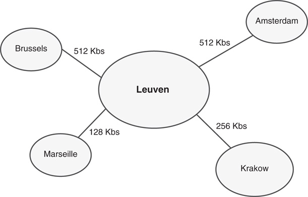
Viewing a Hub-and-Spoke Replication Design
CompanyA is a glass manufacturer with a central factory and headquarters located in Leuven, Belgium. Four smaller manufacturing facilities are located in Marseille, Brussels, Amsterdam, and Krakow. WAN traffic follows a typical hub-and-spoke pattern, as diagrammed in Figure 7.9.
CompanyA decided to deploy Windows Server 2016 to all its branch locations and allocated several DCs for each location. Sites in AD DS were designated for each major location within the company and given names to match their physical location. Site links were created to correspond with the WAN link locations, and their replication schedules were closely tied with WAN utilization levels on the links themselves. The result was a Windows Server 2016 AD DS site diagram that looks similar to Figure 7.10.
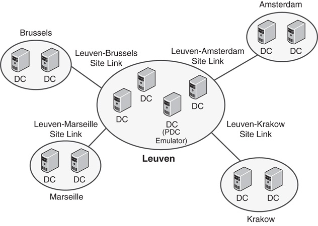
Both DCs in each site were designated as a preferred bridgehead server to lessen the replication load on the GC servers in the remote sites. However, the PDC emulator in the main site was left off the list of preferred bridgehead servers to lessen the load on that server. Site link bridging was kept activated because there was no specific need to turn off this functionality.
This design left CompanyA with a relatively simple but robust replication model that it can easily modify at a future time as WAN infrastructure changes.
Decentralized Replication Design
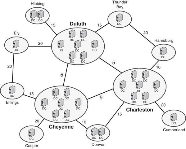
CompanyB is a mining and mineral extraction corporation that has central locations in Duluth, Charleston, and Cheyenne. Several branch locations are distributed across the continental United States. Its WAN diagram utilizes multiple WAN links, with various connection speeds, as diagrammed in Figure 7.11.

CompanyB recently implemented Windows Server 2016 AD DS across its infrastructure. The three main locations consist of five AD DS DCs and two GC servers. The smaller sites use one or two DCs for each site, depending on the size. Each server setup in the remote sites was installed using the Install from Media option because the WAN links were not robust enough to handle the site traffic that a full DC promotion operation would involve.
A site link design scheme, like the one shown in Figure 7.12, was chosen to take into account the multiple routes that the WAN topology provides. This design scheme provides for a degree of redundancy, as well, because replication traffic could continue to succeed even if one of the major WAN links was down.
Each smaller site was designated to cache universal group membership because bandwidth was at a minimum and CompanyB wanted to reduce replication traffic to the lowest levels possible, while keeping user logons and directory access prompt. In addition, traffic on the site links to the smaller sites was scheduled to occur only at hour intervals in the evening so that it did not interfere with regular WAN traffic during business hours.
Each DC in the smaller sites was designated as a preferred bridgehead server. In the larger sites, three DCs with extra processor capacity were designated as the preferred bridgehead servers for their respective sites to off-load the extra processing load from the other DCs in those sites.
This design left CompanyB with a robust method of throttling replication traffic to its slower WAN links, but at the same time maintaining a distributed directory service environment that AD provides.
Deploying Read-Only Domain Controllers
A concept introduced in Windows Server 2008, and supported in Windows Server 2016 is the read-only domain controller (RODC) server role. RODCs, as their name implies, hold read-only copies of forest objects in their directory partitions. This role was created to fill the need of branch office or remote site locations, where physical security might not be optimal and storing a read/write copy of directory information is ill advised.
Understanding the Need for RODCs
Before Windows Server 2008, DCs could only be deployed with full read/write replicas of domain objects. Any change initiated at a DC would eventually replicate to all DCs in the forest. This would occur even if the change was undesirable, such as in the case of a security compromise.
In remote sites, physical security was an issue for these DCs. Although organizations didn’t want to deploy DCs to these sites for security reasons, in many cases slow WAN links would dictate that the remote office would need a local DC, or run the risk of diminished performance in those sites.
In response to these issues, Microsoft built the concept of RODCs into Windows Server AD DS. They also built functionality in RODCs that allowed only specific passwords to be replicated to these RODCs. This greatly reduces the security risk of deploying DCs to remote sites.
Features of RODCs
Several key features of RODCs must be understood before they are deployed in an organization, including the following:
![]() RODCs can be installed on a server with Windows Server 2016 Server Core, to further reduce the security risk by reducing the number of services running on the server.
RODCs can be installed on a server with Windows Server 2016 Server Core, to further reduce the security risk by reducing the number of services running on the server.
![]() RODCs can be configured as GC servers, which effectively makes them ROGCs.
RODCs can be configured as GC servers, which effectively makes them ROGCs.
![]() Domain and forest functional levels must be set to Windows Server 2003 or higher levels to install RODCs.
Domain and forest functional levels must be set to Windows Server 2003 or higher levels to install RODCs.
![]() Replication to RODCs is unidirectional; there is nothing to replicate back from the RODCs.
Replication to RODCs is unidirectional; there is nothing to replicate back from the RODCs.
![]() RODCs that run the domain name system (DNS) service will maintain a read-only copy of DNS partitions, as well. Clients who need to write their records into DNS will be issued a referral to a writable DNS server. The record that they write will be quickly replicated back to the RODC.
RODCs that run the domain name system (DNS) service will maintain a read-only copy of DNS partitions, as well. Clients who need to write their records into DNS will be issued a referral to a writable DNS server. The record that they write will be quickly replicated back to the RODC.
Deploying an RODC
The process for deploying an RODC is similar to the process of deploying a regular DC. In both scenarios, the DC promotion wizard (or corresponding PowerShell commandlet) is used to initiate the process. To configure a server as an RODC, follow these steps:
1. Install the AD DS Role from Server Manager or from PowerShell (Add-WindowsFeature–name ad-domain-services–IncludeManagementTools).
2. Start the Active Directory Domain Services Configuration Wizard when prompted (or manually by clicking Notifications—Promote This Server to a DC).
3. From the wizard welcome screen, select Add a DC to an existing domain, and type the domain into the Domain dialog box.
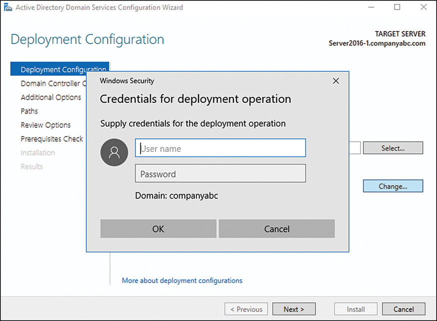
4. Enter credentials of a domain administrator after clicking the Change button, as shown in Figure 7.13, and then click Next to continue.
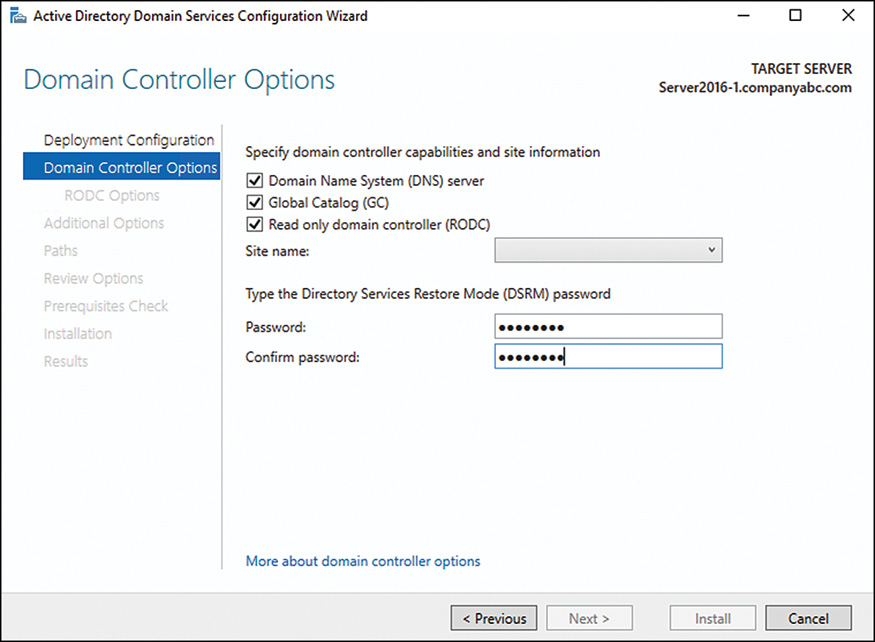
5. Select a site to install the DC into from the list, and check Read Only DC check box, as shown in Figure 7.14. You can also set up the RODC to be a GC server. Enter a Directory Services Restore Mode password, as well, and click Next to continue.
6. On the RODC Options page, shown in Figure 7.15, specify if the passwords of any specific accounts will be replicated to the RODC. Often, local users and passwords in the remote location could be added here to allow for them to be replicated and to improve logon times.
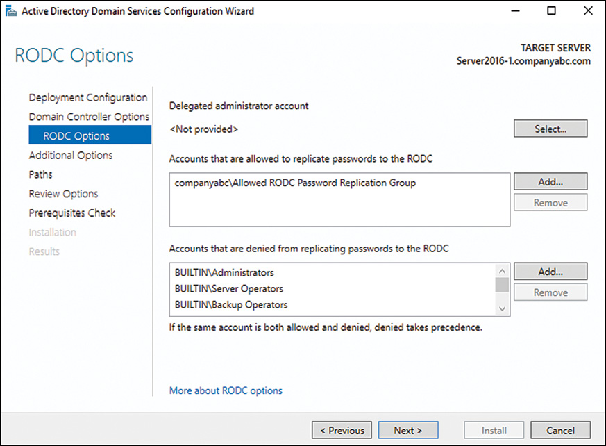
7. On the same page, specify any accounts or groups that will be local administrators on the box. Windows Server 2012 and later removes the requirement that local administrators of RODCs be Domain Admins, which gives greater flexibility for remote site administration of the server. Enter a group (preferred) or user account into the Group or User field, and click Next to continue.
8. On the Additional Options page, choose to replicate either from an existing DC or from local media. By storing the DC information about a burnt CD or other media and shipping it to the remote location, replication time can be greatly reduced. In this case, we are replicating from an existing DC, so select a DC to replicate from and then click Next to continue.
9. The next dialog box on database location, set the location for the SYSVOL, logs file, and database, and click Next to continue.
10. On the Review Options page, review the options chosen, and click Next to continue.
11. After the prerequisites check has completed, click Install to start the process. After several minutes to hours (depending on the size of your AD DS environment), the DC promotion process will be complete, and the RODC will be ready to service requests within the site it is installed in.
Deploying a Clone Virtualized DC
One of the most interesting and useful improvements to AD DS since Windows Server 2012 is the ability to deploy virtual DCs from virtual machine templates. This greatly reduces the overall time it takes to deploy a new AD DS DC, particularly in those environments with a very large number of AD objects.
Prerequisites for Virtualized DC Cloning
The DC running the PDC emulator role cannot be cloned
![]() The Hypervisor that performs the cloning must support VM-Generation ID (Windows Server 2016 Hyper-V currently supports this).
The Hypervisor that performs the cloning must support VM-Generation ID (Windows Server 2016 Hyper-V currently supports this).
![]() You must perform the steps as a member of the Domain Admins group, and the PowerShell commands listed must be run from an elevated command prompt (right-click and select Run as Administrator).
You must perform the steps as a member of the Domain Admins group, and the PowerShell commands listed must be run from an elevated command prompt (right-click and select Run as Administrator).
![]() The PDC emulator role must run on a DC that is running Windows Server 2012 or later.
The PDC emulator role must run on a DC that is running Windows Server 2012 or later.
Adding the Source Virtual DC to the Cloneable DC Group
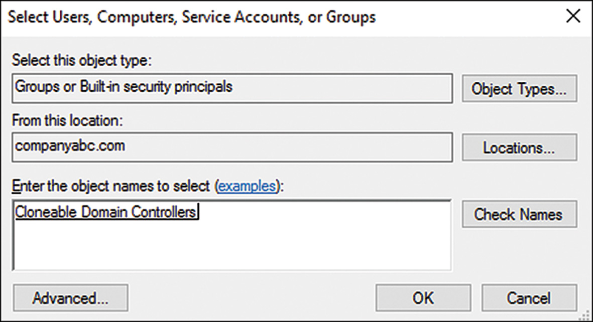
The first step to cloning the DC is to add it to the Cloneable Domain Controllers group in Active Directory. This can be done in Active Directory Administrative Center (ADAC), as shown in Figure 7.16, or it can be inputted via the following PowerShell commandlet (assuming a domain of companyabc.com):
Add-ADGroupMember–Identity "CN=Cloneable Domain
Controllers,CN=Users,DC=companyabc,DC=com"–Member "CN=2016-DC2,OU=Domain
Controllers,DC=companyabc,DC=com"
Running the Excluded App List and New Clone Config File Commandlet
The second set of steps required for cloning a DC are to run a series of PowerShell commandlet that are required for cloning. The first returns a list of applications which must be excluded before cloning the DC. If you choose a standard AD DS installation with only DNS added, there should not be any extra applications in that list. Run the following PowerShell to determine whether any apps need to be excluded in advance:
Get-ADDCCloningExcludedApplicationList
After vetting the list for any apps to be excluded, you can then generate the ADDCClone configuration file. You can specify within the file the name of the DC, any static IP assignments, and DNS and WINS assignments, or you can just use the defaults (DHCP, generated name, and so on) by typing in the following, as shown in Figure 7.17:
New-ADDCCloneConfigFile

Exporting and Importing the Source DC Virtual Machine
To create the clone, the source DC (remember that the source DC cannot be the PDC emulator) must be shut down and exported in Hyper-V. You can do this by just right-clicking the guest session in Hyper-V manager, choosing Export, and specifying an export directory, or you can do so via PowerShell with the following syntax (where 2016-DC2 is the name of the virtual DC session and Hyper-V is the name of the Hyper-V host):
Export-VM–Name 2016-DC2–ComputerName HyperV–Path C:Export
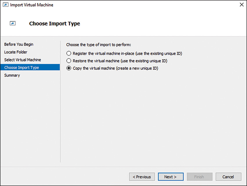
You can then import it via the GUI interface, as a new guest session; just be sure to choose to Copy the Virtual Machine (Create New Unique ID) option, as shown in Figure 7.18, and to choose a new location for the virtual hard drives, snapshots, and smart paging folder. In addition, after cloning, be sure to delete any snapshots. A PowerShell equivalent of the process requires the following syntax (or similar depending on your variables):
$path = Get-ChildItem "C:Export2010-DC22010-DC2Virtual Machines"
$vm = Import-VM–Path $path.fullname–Copy–GenerateNewID
Rename-VM $vm VirtualDC2
Get-VMSnapshot VirtualDC2 | Remove-VMSnapshot–IncludeAllChildSnapshots
Restarting the Source DC and Bringing the Clone DC Online
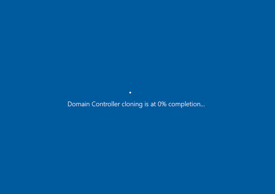
You can import the DC multiple additional times to bring up more DCs, up to 16 at a time, but be sure to change the file locations where the VHDs, snapshots, and smart paging folder are located each time. When you are done creating replicas, bring the original source DC back online and verify it in AD DS. At this point, you need simply to bring the clone DC (or DCs, for multiple copies) back online, and the cloning process will then proceed automatically, as shown in Figure 7.19.
Summary
The separation of the directory model from the replication model in Windows Server 2016 AD DS allows domain designers to have full flexibility when designing replication topology and enables them to focus on replication efficiency. In addition, several features in Windows Server 2016, such as virtual DC cloning, RODCs, IPv6 support, universal group caching, and install from media DC promotion, give the replication topology an even greater edge and allow for the realization of improved replication times and reduced bandwidth.
Best Practices
The following are best practices from this chapter:
![]() Use RODCs to allow for local DC functionality in sites with lessened security.
Use RODCs to allow for local DC functionality in sites with lessened security.
![]() Consider using virtualized DC cloning to more quickly deploy virtualized DCs.
Consider using virtualized DC cloning to more quickly deploy virtualized DCs.
![]() Consider installing dedicated DCs using Server Core, to reduce the overall security profile that a server presents.
Consider installing dedicated DCs using Server Core, to reduce the overall security profile that a server presents.
![]() Use the automatically generated connection objects that are created by the KCC, unless a specific reason exists to hard-code replication pathways.
Use the automatically generated connection objects that are created by the KCC, unless a specific reason exists to hard-code replication pathways.
![]() Ensure that all your sites listed in DNS contain the appropriate SRV records.
Ensure that all your sites listed in DNS contain the appropriate SRV records.
![]() Use the new PowerShell replication commandlets to troubleshoot and validate AD DS replication.
Use the new PowerShell replication commandlets to troubleshoot and validate AD DS replication.
![]() Consider using IPv6 for environments consisting of Windows 8 and later client operating systems and Windows Server 2008 and later server operating systems . . . and other IPv6-compliant devices.
Consider using IPv6 for environments consisting of Windows 8 and later client operating systems and Windows Server 2008 and later server operating systems . . . and other IPv6-compliant devices.
![]() Use IPv6 tunneling mechanisms such as ISATAP and 6to4 to provide long-term compatibility between IPv4 and IPv6.
Use IPv6 tunneling mechanisms such as ISATAP and 6to4 to provide long-term compatibility between IPv4 and IPv6.
![]() Do not turn off site link bridging unless you want to make your DC replication dependent on the explicit site links that you have established.
Do not turn off site link bridging unless you want to make your DC replication dependent on the explicit site links that you have established.