
CHAPTER 10
DHCP, IPv6, IPAM
IN THIS CHAPTER
![]() Understanding the Components of an Enterprise Network
Understanding the Components of an Enterprise Network
![]() Exploring the Dynamic Host Configuration Protocol
Exploring the Dynamic Host Configuration Protocol
![]() Exploring DHCP Changes in Windows Server 2016
Exploring DHCP Changes in Windows Server 2016
![]() Exploring Advanced DHCP Concepts
Exploring Advanced DHCP Concepts
![]() Windows Server 2016 DHCP Failover
Windows Server 2016 DHCP Failover
![]() Exploring Advanced DHCP Concepts
Exploring Advanced DHCP Concepts
![]() Configuring IPv6 on Windows Server 2016
Configuring IPv6 on Windows Server 2016
![]() Installing the IPAM Server and Client Features
Installing the IPAM Server and Client Features
![]() Configuring Servers for IPAM Management
Configuring Servers for IPAM Management
Connecting new servers and workstations to the network requires network connectivity and the ability to find the required resources to properly authenticate the computer and users accounts. This is accomplished with proper network connectivity, network addressing, and name resolution. In the preceding chapter, you learned about the domain name system (DNS) and Windows Internet Naming Service (WINS), which are the primary name-resolution services used by network-connected systems today. This chapter provides an overview and detailed information for system administrators to properly implement automated network addressing solutions using the Dynamic Host Configuration Protocol (DHCP) services provided with Windows Server 2016. This chapter also covers IPv6, DHCP configuration, and the new Microsoft feature IP Address Management (IPAM) server and client.
Understanding the Components of an Enterprise Network
Whether an enterprise, midsize, or small business network, all connected systems require proper IP addressing and name resolution to function. When a new system is to be connected to the network, it must be configured with network address settings sufficient enough to authenticate the user logging on and to locate the network resources that the user/computer account require. This is accomplished with a layered approach of network addressing, name resolution, and domain identification and authentication.
The Importance of Network Addressing
This book details the implementation of Windows Server 2016 and assumes that the network will be based on Microsoft networking. Regardless of whether Microsoft, UNIX, Mac, or a different operating system provides the network backbone, network addressing is the key to intercomputer communication. Anything and everything about computer networking is based on locating and accessing resources stored on multiple systems so that users can collaborate and share information. This is possible with network addressing and, to make it simpler, name resolution.
With today’s infrastructure consisting of both local company-owned resources intertwining with cloud or Internet-based hosted applications, name resolution is key to successful functionality for computer systems and users on these networks. Name resolution for Internet and intranet connectivity is detailed in the preceding chapter. This chapter focuses more on automated network connectivity provided by DHCP for both IPv4 and IPv6 and also covers the new feature IPAM.
IP address management has always been a task associated with managing an organization’s network. Until now, however, this task has mostly been performed by relying on WINS and DNS records and on text files, spreadsheets, custom applications or databases, and third-party products. Microsoft Windows Server 2016 includes the IPAM feature, which provides administrators with a centralized complete view of the IP landscape, to not just to keep track of IP addresses, but also to audit changes and implement changes through the one central console.
Name Resolution
Name resolution refers to the identification of a network-connected system by a friendly name as opposed to a network IP address. Connecting to a network resource by its actual network address is possible within certain constraints, but with today’s security and application features and functionality, connecting to a system by its name is not only ideal, it may be required. For example, in many common hosted implementations, a single network address may resolve to many different names and present different applications, websites, and services based each unique name.
Name resolution is the resolution of a network-connected resource by name and a matched IP address or a different name or alias name. This could be a short name such as WEBSERVER1 or a fully qualified domain name (FQDN) such as www.companyabc.com resolving to an IP address of 10.1.1.10.
Name Resolution and Directory Integration
With Microsoft Active Directory (AD) and many networking services, name resolution provides detailed information about how to connect to a particular service. For example, with Windows Server 2016 DNS servers and clients, a client system looking to find a Global Catalog server is presented not only with a list of names and IP addresses, it is also provided with the closest system to the network the system is connected to, and it also presents the port the client can connect to that service on. So, instead of just a name to IP address, advanced name-resolution services can make distinctions of the client location and provide a detailed response that improves network connectivity.
DHCP Failover
Windows Server 2016 DHCP services includes DHCP failover. This service obviates the need for the split-scope design and the response delay that allowed DHCP administrators to enable redundancy. Using the split scope still required reservations and active leases to be managed separately. Another option was and still is to deploy DHCP services on a failover cluster, but that adds on the complications of managing a failover cluster system and leveraging a shared storage subsystem or an external data replication system.
With Windows Server 2016 DHCP failover, redundancy is achieved through the DHCP services on each system monitoring and updating one another on leases, reservations, scope settings, and service availability. This makes this new enhancement a great addition to the many new features and services already included in the DHCP server role.
Windows Server 2016 IPAM Overview
The IPAM feature included with Windows Server 2016 provides network administrators with a single centralized console from which they can view and manage the IP addresses of the entire enterprise. This feature supports the discovery of servers providing IP-related services and includes tasks to collect and organize data from these servers in single functional console. The IPAM feature collects data from DNS, DHCP, domain controller (DC), and Network Policy Server (NPS) servers that are registered to the particular IPAM server and presents the data in several default views that are searchable and easily manipulated and exportable. IP address audit tracking and even changes to existing service configurations and records are just a few of the tasks that this new feature enables. More information about Windows Server 2016 IPAM is detailed later in this chapter.
Exploring DHCP
Understanding how DHCP works is an important part of a network administrator’s list of skills. In today’s networks, the DHCP service is used by workstations, some servers, Preboot Execution Environment (PXE) network boot clients, printers, mobile devices such as a smartphone or tablet, IP-based phones, and data scanners. Some Windows Server 2016 services, such as the Windows Deployment Server role services, interact, and depend on DHCP to properly function.
The Need for DHCP
Network administrators cannot expect end users and even IT personnel to be able to manually configure each network device’s IP address settings. Furthermore, end users should not even have the permissions to change network configurations. Because of these and other challenges, DHCP services are required on most networks to enable network connectivity. Also, many devices do not provide an interface simple enough or readily available to configure network settings. DHCP provides a simple way to not only deliver IP addressing from a central administrative point, but it also allows the network administrators to control how these devices actually connect to the network and greatly enhance the management of these network-connected devices through this service.
Outlining DHCP Predecessors: RARP and BOOTP
Before the DHCP service was developed, two predecessors provided the first implementations of automated IP addressing. The first was the Reverse Address Resolution Protocol (RARP), and the second was the Bootstrap Protocol (BOOTP).
To understand RARP, an IT administrator should first understand the Address Resolution Protocol (ARP). Each network adapter, wired or wireless, has a unique address burned into it. This address never changes and it called the Media Access Control (MAC) address. The ARP stores IP address-to-MAC address information. For example, if you know the IP address of a system on the network, the ARP table will provide the corresponding MAC address associated with that IP address. On most systems and network devices, the ARP table is continuously built dynamically based on previous and current connections, but only for systems on the same network segment. RARP tables, however, are the reverse in both the fact that they are not dynamically built and they are MAC-to-IP resolution.
The RARP service allows a newly connected system to broadcast its MAC address on the network and the RARP service will respond with the assigned IP address. This allows the new system to basically connect dynamically to the network. A few catches exist, however. The first catch is that the RARP administrator must first collect that new system’s MAC address and create an entry on the RARP table on the service with a corresponding IP address. The next catch is that RARP delivers a system an IP address but no other networking information, such as a subnet mask, router IP address, or DNS server or other networking options. The RARP service was limited to usage on a single flat network, but was useful in its time.
The next predecessor is the BOOTP service. The BOOTP service provided an IP address to clients requesting one, but did not require a predefined table of related MAC and IP addresses. BOOTP was designed to not only get a system connected, but to also provide additional information to systems looking to load or boot an operating system stored on the network. BOOTP is still used today for some network boot implementations but has been superseded by the DHCP service.
Exploring the DHCP Server Service
The DHCP server service continues the decades old implementation of automated network addressing. The DHCP server service can provide all the same functionality of a BOOTP service, but can also provide additional information to clients who are requesting an IP address. The DHCP server service provides a client an IP address in three steps:
1. DHCP client boots and broadcasts a DHCP IP request to all nodes on the local network.
2. A DHCP server on the local network receives the request and prepares to distribute an IP address to this client in the form of a DHCP IP address lease.
3. After the DHCP server has determined the right prerequisite information from that client request, it issues the client with a DHCP IP address lease, including additional DHCP lease options such as subnet mask, default gateway, and most likely, DNS server IP addresses.
Examining the DHCP Client Service
The DHCP client service is the client-side service that requests an IP address from the network. Depending on the system’s network adapter configuration, the DHCP client service may be active or inactive and, if the client is leveraging network boot, can come in the form of a BOOTP or PXE client controlled by the system board. The Windows DHCP client service, however, is managed by the configuration stored within the Microsoft operating system and, furthermore, on each adapter. If the adapter senses a network connection and the IP address configuration is configured for automated IP addressing, the DHCP client service broadcasts the request for an IP address, and when the data is received from the server, the DHCP client service applies the lease information to the appropriate adapter and enables network communications. With the DHCP IP address lease, there is an important piece of information delivered, known as the lease duration. The lease duration informs the client how long the IP address can be used before the client must check back with the DHCP server to renew the lease or get a new lease. The DHCP client caches this information, and when the lease duration is nearly up or when the system is restarted or the network is reinitialized, the DHCP client contacts the DHCP server to ensure the lease can still be used so that it can be renewed or replaced with a new lease.
In addition, on Microsoft systems, the DHCP client service also manages the Dynamic DNS registration of the client if there is a Dynamic DNS server available. This is true unless the DHCP server service is mandating that DHCP leases have their dynamic DNS registration handled by the server itself.
Automatic Private IP Addressing
Automatic Private IP Addressing (APIPA) is a feature of Windows clients and servers that allows systems on the same network to automatically establish network connectivity and communication with one another when no DHCP server is available. This is a great feature for a very small network where a set of machines need to share data and communicate with one another with little or no IT support. The IP addresses automatically assigned to adapters with this configuration are in the 169.254.0.0/16 subnet range. APIPA is enabled on all Windows clients by default. When a Windows client cannot locate a DHCP server and assigns itself with an automatic private IP address, it may not readily detect when a DHCP server comes online and may remain off the network unnecessarily long. APIPA cannot be disabled on Windows 8 and Windows Server 2016 systems except by disabling DHCP altogether.
DHCP Relay Agents
A DHCP relay agent can play a critical role on an enterprise network, allowing DHCP services to be extended across routers and different networks. When a DHCP client broadcasts a DHCP client broadcast, that broadcast is normally only allowed on the local network, which means that if there is no local DHCP server, there is no DHCP server response. Two ways to circumvent this limitation, or really this feature, is to either locate a DHCP server in each network or configure a DHCP relay agent on each remote network. The role of a DHCP relay agent is to pick up the local DHCP client broadcast and to forward that request to a designated DHCP server on a remote network. The remote DHCP server must, of course, be configured with a scope of IP addresses for that network, and when responding provides that lease information to the DHCP relay agent, which delivers that information to the client. This allows for DHCP services to be located centrally and managed by Windows Server 2016 systems, while the DHCP relay agent service can be provided by Windows clients, servers, or network devices such as switches, routers, or firewalls.
DHCP and Dynamic DNS Integration
The Windows Server 2016 DHCP service provides direct integration with the Dynamic DNS (DDNS). All Windows clients and servers are configured by default to register their name and IP address with the designated domain name system (DNS) server as configured manually or by DHCP on their respective network card IP settings. When a DNS server is configured to allow networking clients to automatically register their records within DNS zones, this functionality is referred to as Dynamic DNS registration. With a Windows Server 2016 DHCP server, this functionality can be extended to not only Windows clients leasing an IP address from the DHCP server but to any DHCP client. The DHCP server can, in fact, register the name and IP address on the DNS zone on behalf of the client using its own server computer account or a specified user account that has been granted rights to register DNS records. For more information about Dynamic DNS registration refer to Chapter 9, “Domain Name System, WINS, and DNSSEC.” For information about configuring Dynamic DNS configuration with DHCP, see the section “DHCP and Dynamic DNS Configuration,” later in this chapter.
Installing DHCP Server and Server Tools
The DHCP role can be installed on a Windows Server 2016 system at any time using the Server Manager console. If the DHCP server tools are required on the local DHCP server, they can be selected for installation during the role installation or at a later time. Ideally, IT shops now are making the move toward centralized management, and this in many cases means no management tools on each server. To install the DHCP role and server tools on a single system, follow these steps:
1. Log on to the proposed DHCP server.
2. Click the Server Manager tile on the taskbar.
3. When the Server Manager console opens, on the Welcome to Server Manager page, click Add roles and features in the right pane, as shown in Figure 10.1.
4. On the Before You Begin page, in the Add Roles and Features Wizard, click Next to continue.
5. On the Select Installation Type page, select the Role-based or Feature-based Installation radio button, and then click Next to continue.
6. On the Select Destination Server page, select the Select a Server from the Server Pool radio button and select the local server in the window. Click Next to continue.
7. On the Select Server Roles page, check the DHCP Server role, and in the Add Roles and Features Wizard pop-up window, click Add Features to also install the DHCP Server Tools. Click Next to continue.
8. On the Select Features page, scroll down to the Remote Server Administration Tools Features group, expand it, and expand the Role Administration Tools group and verify that the DHCP Server Tools Feature is also selected. Then click Next to continue.
9. On the DHCP Server page, read the information and click Next to continue.
10. On the Confirm Installation Selections page, click Install to begin the installation. If a reboot is required, you are prompted after the installation completes. Reboot as required.
11. From the Installation Progress page, you can monitor the installation progress, but do not close the window.
12. When the installation completes, click the Complete DHCP Configuration link on the Installation Progress page, as shown in Figure 10.2. Running this wizard creates the DHCP Administrators and the DHCP Users security group on the local machine and authorizes this server in Active Directory.
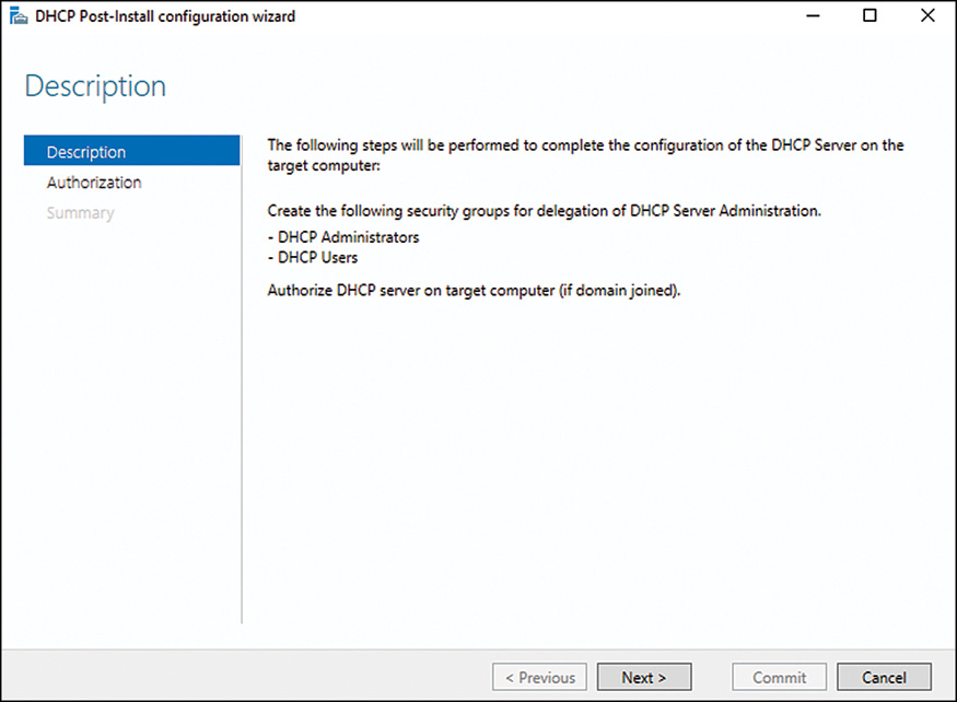
13. On the Description page of the DHCP Post-Install Wizard, click Next to continue.
14. On the Authorization page, if the current logon account has the rights to authorize this server in Active Directory, click Commit to complete the task. If another account is required, enter the appropriate credentials and click Commit.
15. On the Summary page, verify the security groups were created and that authorization has completed. Click Close in the Post-Install Wizard window and click Close again in the Add Roles and Features Wizard window.
After the installation completes, you are returned to the Server Manager window. This Post-Install Wizard includes authorizing the DHCP server and creating the local groups DHCP Administrators and DHCP Users for DHCP server delegation.
DHCP authorization is the process of registering a new server in Active Directory to allow it to provide DHCP services on the network. This wizard should be run after all DHCP server installations. However, if DHCP server authorization is not necessary, skip authorization and just let the wizard create the delegation groups.
This completes the DHCP server and server tools installation task.
Creating IPv4 DHCP Scopes
Before a DHCP server can be useful, it must be authorized, and a scope must be created and activated. DHCP authorization can be performed using the DHCP Post-Install Wizard or it can be performed from within the DHCP server console. This section details how to create a basic DHCP IPv4 scope on a newly authorized DHCP server. To create a new DHCP IPv4 scope, follow these steps:
1. On a server with the DHCP Server Tools installed, click the Server Manager tile on the taskbar.
2. When the Server Manager console opens, click Tools, and then select the DHCP option.
3. If no servers are listed when the DHCP console opens, right-click DHCP in the tree pane and select Add Server.
4. In the Add Server windows, if the server is already authorized, select it from the Authorized Server section of the window and click OK, as shown in Figure 10.3. If the server is not yet authorized, type in the server name, and then click OK to continue.
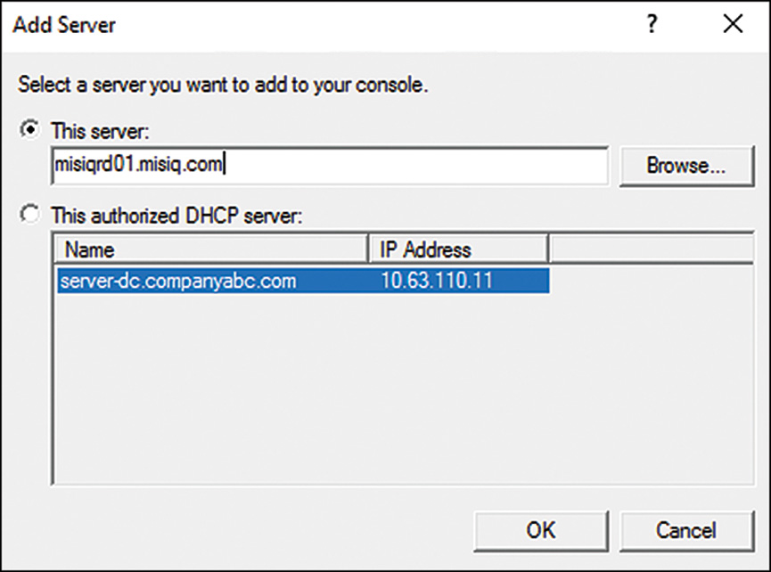
5. After the server is added to the console, expand the server to reveal the IPv4 and the IPv6 nodes. Verify that both nodes show a green checkmark indicating that the server is properly authorized in Active Directory.
6. Select the IPv4 node, and then right-click and select New Scope.
7. Click Next on the Welcome to the New Scope Wizard.
8. On the Scope Name page, provide a description name and description for the new scope, and then click Next to continue.
9. On the IP Address Range page, enter a starting and ending IP address and a corresponding subnet mask for the new scope, and then click Next to continue, as shown in Figure 10.4.

10. On the Add Exclusions and Delay page, enter any IP address exclusion ranges or DHCP subnet delay intervals, and then click Next to continue.
NOTE
DHCP administrators wanting to deploy redundant servers or split-scope ranges should leave the fields on the Exclusion and Delay page blank and run the Failover or Split-Scope Wizards to achieve the desired redundancy configuration.
11. On the Lease Duration page, adjust the lease duration from the default of 8 days to the desired IP address lease duration and click Next to continue. Typical durations include 1 day, 8 hours, or 30 days, depending on the policy.
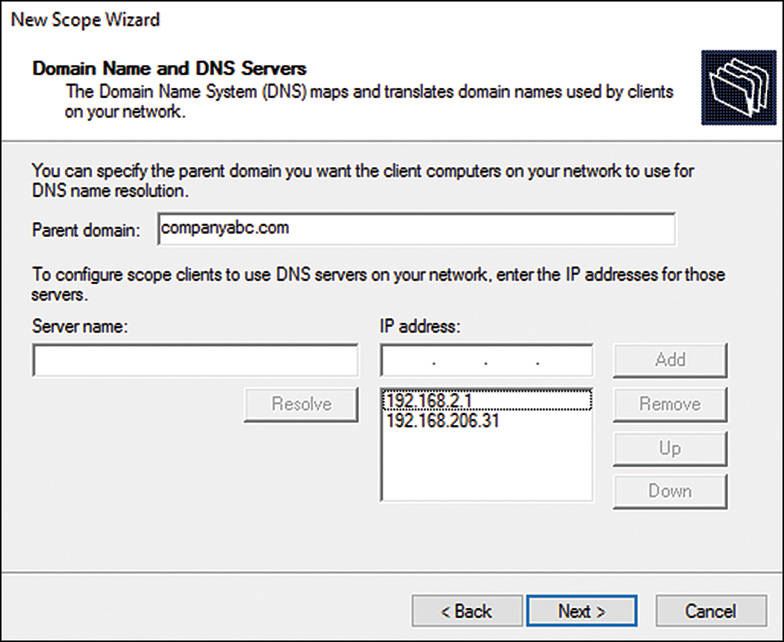
12. On the Configure DHCP Options page, select the Yes I Want to configure Options Now radio button and click Next to continue. The wizard then steps through the configuration for the most common DHCP scope options that administrators desire, such as the Router (Default Gateway) option, the Domain Name Suffix & DNS Servers, and WINS Servers.
13. On each of the options pages, enter the appropriate information and click Next to continue, as shown in Figure 10.5, when configuring the domain name suffix and the DNS servers.
14. On the Activate Scope page, select the Yes, I Want to Activate This Scope Now radio button, and then click Next.
15. Click Finish on the Completing the New Scope Wizard page.
16. After the scope has been created, expand the IPv4 node to reveal the new scope and review each of the subnodes to ensure the correct settings were deployed.
This completes the deployment of a new IPv4 DHCP scope.
Exploring DHCP Changes in Windows Server 2016
The Windows Server 2016 DHCP server service has added some new improvements to its features. One of the biggest improvements is the new DHCP failover functionality that allows synchronization of DHCP leases and scope information between servers. Before you can enable that functionality, however, DHCP server roles must be deployed on multiple systems, and at least one of these systems must already have a DHCP scope defined.
On most networks, before this new DHCP feature can be leveraged, existing DHCP servers and their scopes must be migrated/decommissioned. The following section details the migration options available for DHCP migration using the Windows Server 2016 Migration Tools.
Migrating DHCP Servers Using Windows Server Migration Tools
The Windows Server 2016 Window Server Migration Tools are a set of tools designed to aid administrators with the migration of not only DHCP scope information, but also the current leases, reservations, and scope options.
Installing the Windows Server Migration Tools on Windows Server 2016
Before the migration tools can be leveraged, they must be installed on all the source and destination servers. Because the tools are included with Windows Server 2016, they must first be installed on Windows Server 2016, and then a special deployment folder package must be created to support installation on down-level operating systems. To install migration tools on a Windows Server 2016 system, follow these steps:
1. Log on to the proposed Windows Server 2016 system and click the Server Manager tile on the taskbar.
2. When the Server Manager console opens, on the Welcome to Server Manager page, click Add Roles in the center.
3. On the Before You Begin page, in the Add Roles and Features Wizard, click Next to continue.
4. On the Select Installation Type page, select the Role-Based or Feature-Based Installation radio button, and then click Next to continue.
5. On the Select Destination Server page, select the Select a Server from the Server Pool radio button and select the local server in the window. Click Next to continue.
6. On the Select Server Roles page, leave the defaults and click Next to continue.
7. On the Select Features page, scroll down to Windows Server Migration Tools Features group and check the box, and then click Next, as shown in Figure 10.6.

8. On the Confirm Installation Selections page, click Install to begin the installation. If a reboot is required, you are prompted after the installation completes. Reboot as required.
9. On the Installation Progress page, you can monitor the installation progress. Click Close when the installation completes.
Creating the Deployment Folder Package of the Windows Server Migration Tools for Down-Level Operating System Installation
Before the Windows Server migration tools can be used to migrate DHCP services from older operating systems to Windows Server 2016, the tools must be installed on the down-level operating systems. For the Windows Server 2016 migration tools, this includes Windows Server 2012 and 2012 R2, and Windows Server 2008 and 2008 R2 (Windows Server 2003 is no longer supported). The process is mostly the same for all versions and includes two steps: creating the deployment folder package and then installing that package on the down-level system. To create the deployment folder package for a Windows Server 2012 R2 x64 system, follow these steps:
1. On the Windows Server 2016 system with the Windows Server migration tools installed, open an elevated PowerShell console session.
2. Change directories to C:WindowsSystem32ServerMigrationTools, assuming that the C: drive is the system drive.
3. Type the command .SmigDeploy.exe /package /architecture amd64 /OS WS128R2 /path C:MigTools and press Enter to create the package.
4. After the package is created, you should have a C:MigToolsSMT_WS128R2_amd64 folder created. You can repeat the previous command for all Windows Server versions including Windows Server 2008 and later for both 32- and 64-bit editions as required. Close the command prompt.
This completes the creation of the down-level deployment folder package.
Installing the Windows Server Migration Tools on Windows Server 2012 R2 64-Bit Edition DHCP Server
After the deployment folder package has been created, you can copy it over to the destination server and install it. To install the deployment package on previous version of Windows Server, follow these steps:
1. Copy the C:MigToolsSMT_ws12R2_amd64 folder from the Windows Server 2016 system to the C:MigTools folder on the destination Windows servers. Create the C:MigTools folder as required or select another desired destination folder.
2. After the folder is copied over, open an elevated PowerShell console session and change the directory to C:MigToolsSMT_ws12R2_amd64.
3. Type SmigDeploy.exe and press Enter to register and install the tools. If Windows PowerShell is not installed, this process fails, and the PowerShell feature must be installed before this process can continue.
4. When the process completes, both the original PowerShell console session and a new PowerShell window are open. Type Exit and press Enter in both windows to close them.
This completes the registration and installation of the Windows Server migration tools on a Windows Server 2012 R2 system. This process is the same for both Windows Server 2012 /R2 and 2008/2008 R2, including the prerequisite of Windows PowerShell for installation and operation.
Migrating DHCP Services from 2012 R2 to Windows Server 2016
After all the tools are installed on the source and destination servers, you can perform the export and import process. Aside from the export and import process, after the export is completed on the source server, the source server IP address must be changed, and the original source server IP address must be added to the destination server for the import and DHCP operation to be seamless.
Preparing the Source Windows Server 2012 R2 DHCP Server for Export
After the migration tools are copied to the source Window Server 2012 R2 DHCP server, the migration process can be started.
1. Log on to the source Windows Server 2012 R2 DHCP server and open the DHCP console.
2. Add the local server to the DHCP server console (if not already present), and then select and right-click the server and select Add/Remove Bindings. Note the current IP address of the server because this is used later. Click Cancel in the window to close it.
3. Right-click the server again, select All Tasks, and then select Stop to stop the DHCP service on that system.
4. Select Start, All Programs, Administrative Tools, Windows Server Migration Tools, and then click the Windows Server Migration Tools PowerShell link.
5. When the PowerShell window opens it should default to the C:MigTools SMT_ws12R2_amd64 folder. Type ./Servermigration.psc1 and press Enter to open a new PowerShell window. This step may seem redundant, but greatly simplifies the process.
6. In the new PowerShell window, type Export-SmigServerSetting -FeatureID DHCP and press Enter.
7. When prompted for the path, enter C:MigToolsExport and press Enter.
8. When prompted for a password, enter a password with at least six characters and press Enter to continue. The process creates the export folder and returns the results into the PowerShell windows, as shown in Figure 10.7.

9. After the export completes, open the services applet on the source server and set the DHCP server service to Disabled, then close the services applet.
10. Copy the C:MigToolsExport folder to the destination Window Server 2016 system.
11. After the export has completed and the DHCP server service is disabled, change the IP address of the source server to something other than the IP address that was originally bound to the DHCP service.
12. Shut down or reboot the source server as required.
Preparing the Destination Windows Server 2016 DHCP Server for Import
After the export process has completed and the export data has been copied to the destination server, the original server can have its IP address changed and can be shut down or rebooted. After that process has completed, the import process on the Windows Server 2016 destination server can commence. To perform the import process, follow these steps:
NOTE
Running this import procedure overwrites all DHCP data, so as a best practice do not install the DHCP server service before this import or use the -Force option when running the import.
1. Log on to the destination Windows Server 2016 DHCP server and change the network IP address to the IP address originally bound to the source DHCP server.
2. Reboot the server to ensure that proper DNS registration is now updated and that all services are running under the new IP address.
3. After the server has rebooted, log back in and open the Server Manager.
4. When the Server Manager console opens, click Tools, and then select the Windows Server Migration Tools option.
5. If necessary, change to the C:WindowsSystem32ServerMigrationTools folder. At the correct path, type ./Servermigration.psc1 and press Enter to open a new PowerShell window.
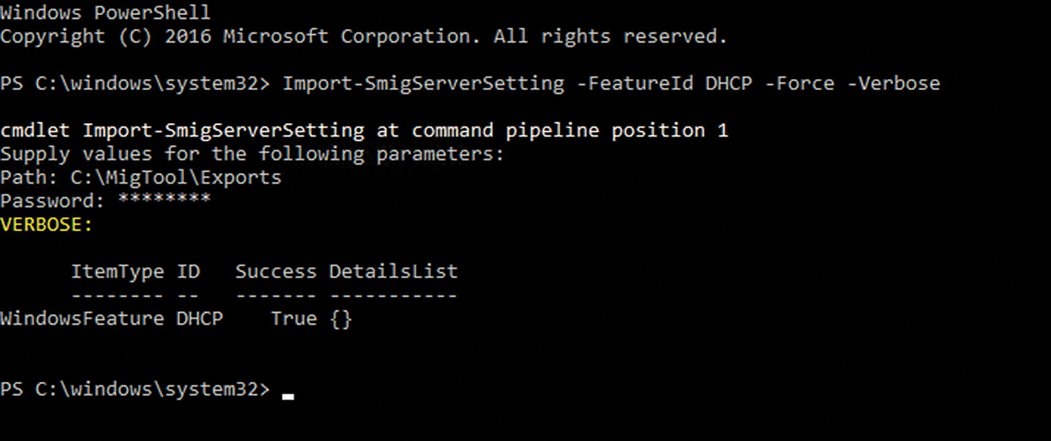
6. In the new PowerShell window, type the command Import-SmigServerSetting -FeatureID DHCP -Force -Verbose and press Enter. For this example, we are using the -Force option because the DHCP server service has already been installed, even though it has not been configured.
7. When prompted for the path, enter C:MigToolsExport and press Enter to continue.
8. When prompted for the password, enter the password previously used during the export process on the source server and press Enter to continue.
The PowerShell window displays the current status of the import process and when completed displays the results and whether a reboot is required, as shown in Figure 10.8.
9. If needed, reboot the server and log on and verify that the original source server IP address is still bound to this Windows Server 2016 system.
10. Open the Server Manager, click Tools, and then select the Services option.
11. Verify that the DHCP server service is set to automatic startup and if necessary start the service.
12. After the server has rebooted, log back on and open the Server Manager.
13. When the Server Manager console opens, select Tools, and then select the Windows Server Migration Tools option.
14. Open the DHCP console, and if necessary add the local server to the console. Right-click the DHCP node in tree pane and select Manage Authorized Servers. If the original source server is listed, unauthorize it. If the current destination server is listed with the incorrect IP address, unauthorize it and close that window.
15. Back in the DHCP console, right-click the local server in the tree pane and expand the IPv4 node and verify that the scope has been successfully imported.
16. Right-click the local server in the tree pane and select Authorize as required.
17. Make any necessary modifications to the scope or scope options as required.
18. Right-click the scope beneath the IPv4 node and select Activate as required.
19. Verify that new DHCP clients can obtain a valid IP address lease.
This completes the DHCP migration process from Windows Server 2012 R2 to Windows Server 2016.
Understanding DHCP Client Alternate Network Capability
Earlier in this chapter, the “Automatic Private IP Addressing” section detailed the Windows client automated IP addressing functionality when a DHCP server is not available. As an extension of that protocol, Windows clients and servers can also default to a fallback IP address lease that can be used when a DHCP server is offline. This can be beneficial to enable complete network connectivity in the event of a DHCP server outage.
A reasonable application of this functionality can be remote network systems that rely on DHCP relay agents that may be less than reliable. On a Windows Server 2016 system, this functionality can be configured as follows:
1. Log on to a Windows Server 2016 system that is configured with DHCP enabled on the network adapter.
2. On the right side of the taskbar, right-click the Network icon and select Open Network and Sharing Center, or right-click the Start button and select Network Connections.
3. When the window opens, in the top-left pane select Change Adapter Settings.
4. In the Network Connections window, right-click the desired network adapter and select Properties.
5. In the Network Adapter window, scroll down and highlight Internet Protocol Version 4 (TCP/IPv4) and press the Properties button.
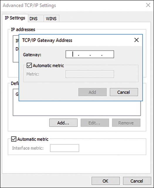
6. Click the Advanced button to open the Advanced TCP/IP settings dialog box, which will let you enter the IP address, DNS, and WINS information.
7. Enter the desired IP address information and click OK, as shown in Figure 10.9.
8. Click OK twice to save the settings and close the Network Connections window.
This completes the configuration of the DHCP client alternate network configuration.
Enhancing DHCP Reliability
On most networks, DHCP is a critical networking service. When the DHCP service is offline, most clients cannot function and may be unable to work at all. For most organizations, building redundancy, reliability, and security into their DHCP service can help alleviate undesired and unexpected DHCP networking outages.
Windows Server 2016 leverages several features that can enhance DHCP reliability as outlined in the proceeding sections.
Link-Layer Filtering
Link-layer filtering or MAC address filtering is a feature of the Windows Server 2016 DHCP service that can be enabled to provide a higher level of security to DHCP leases.
Link-layer filtering basically can restrict which devices are allowed and which devices are denied the ability to obtain a DHCP lease from the DHCP server. For this feature to function, the server must be enabled to support the Allow/Deny Link Layer Filter lists, and the lists must be populated.
In many DHCP deployments, it can be cumbersome for administrators to manually enter each network-connected device’s MAC address before it can be granted a DHCP lease, so link-layer filtering may seem like it is out of reach. One way to avoid this issue is to deploy DHCP in a phased approach. First, deploy DHCP services without Link Layer Filtering enabled. Later, after all clients have connected to the network, add leases to the filter lists as leases are obtained. This can even be performed with DHCP reservations. For example, suppose you set up a DHCP scope on Monday morning and later that afternoon most of your clients have obtained a lease. You can simply select and right-click a single or a set of current leases and select Add to Filter and Allow or Deny depending on which filter list you want the system to be on, as shown in Figure 10.10.
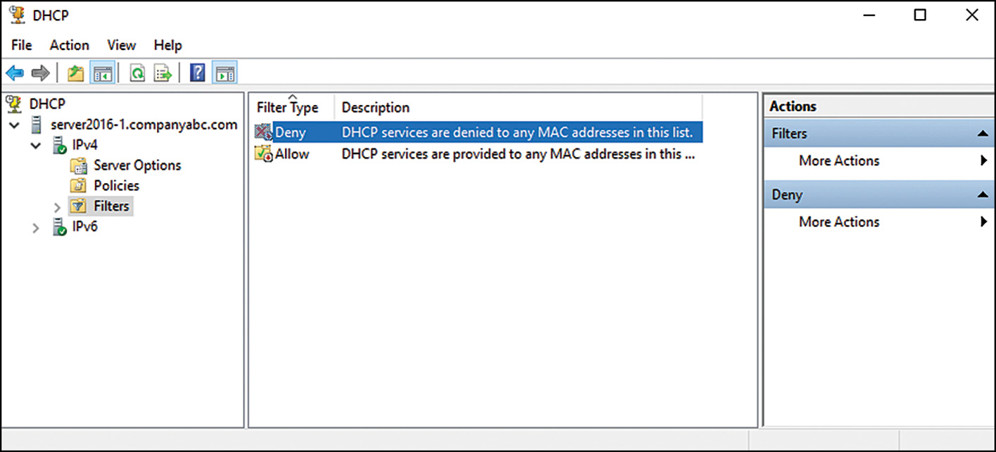
After adding all your leases to the appropriate filter list, in the DHCP console, right-click the IPv4 node and select Properties. On the Filters tab, select the check boxes to enable Allow or Deny Lists, as desired.
DHCP Reservations
A DHCP reservation is a predefined relationship between an IP address and a system’s MAC address. This configuration allows a system to remain configured for DHCP, but it will always get the same IP address that is predefined or reserved for it, hence the name reservation. Reservations are quite useful on business networks for mobile devices and printers; the mobile device or printer can always be contacted at the same IP address for access and for remote management and so on. The flip side is that if that printer or mobile device moves to another office or network, it will be DHCP ready and will connect to the network without manual network configuration.
Using DHCP reservations along with link-layer filtering allows a DHCP administrator to quickly identify new or unidentified machines and quickly block their access. For example, identified machines can be granted leases, and then all of those leases can be converted to reservations and added to Allow filter lists, and finally, an IP address exclusion list can be created for all IP addresses not currently defined in the reservation list, essentially stopping all new leases from occurring. The only issue with this scenario is that when a new valid machine joins the network the DHCP scope changes need adjustments to allow this new system to connect. In addition, when machines have both wireless and wired network cards, each card requires a different reservation.
You can create DHCP reservations using two different processes. The first and most common process is to manually create a reservation; the second much easier process is to convert a DHCP lease into a reservation. To manually create a DHCP reservation, follow these steps:
1. Collect the desired MAC address from the system that will be associated with this reservation. You can do this on a Windows machine in a command prompt by using the Ipconfig /all command and recording the physical address entry.
2. Open the DHCP console and expand the IPv4 node.
3. Expand the desired scope, select and right-click the Reservations node, and select New Reservation.
4. Enter a descriptive name, IP address, and MAC address for the system, and click Add to create the reservation, as shown in Figure 10.11.
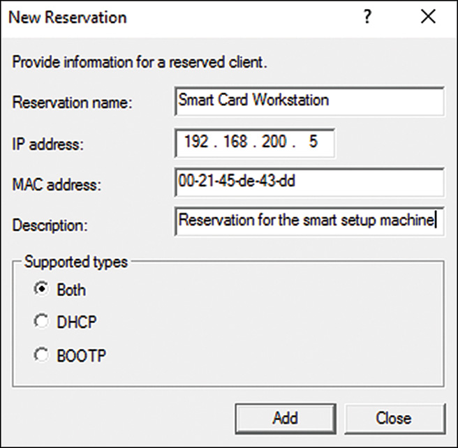
5. When that reservation is completed, the window clears to allow for another reservation to be created. Click Close to return to the DHCP console.
To create a reservation from an existing lease, simply open the IPv4 scope and select the Address Leases node in the tree pane, locate the lease in the center pane, right-click the desired lease or multiple leases, and select Add to Reservation.
This completes the reservation-creation process.
Configuring Reservation-Specific DHCP Scope Options
Sometimes devices are on the same network but require different DHCP scope options. One example could be a kiosk machine that should not have a default gateway or an IP phone that requires additional scope options that are not desired on all DHCP clients. This can be accomplished with reservation-specific DHCP scope options. To create a reservation-specific scope option, create a reservation in the tree pane, expand the Reservations node, and specifically select the desired reservation and select Configure Options. Proceed to select and configure the desired options and save the changes by clicking OK when completed. These reservation-specific options override both scope and server options when configured.
DHCP Name Protection
DHCP name protection is a feature of the DHCP service that when used with Dynamic DNS registration prevents a DHCP client with a name already in the DNS domain zone from registering or overwriting an existing name that it does not own. This functionality prevents client and server spoofing and name corruption for statically configured systems already registered in DNS. You can enable name protection at either the IPv4 or IPv6 node level or at the scope level. When configured at the scope level, the settings take precedence over the IPv4 or IPv6 node settings. To enable DHCP name protection at the scope level, follow these steps:
1. Open the DHCP console and connect to the desired DHCP server.
2. Expand the IPv4 node, select and right-click the desired scope, and select Properties.
3. Display the DNS tab, and near the bottom in the Name Protection section click the Configure button.
4. In the Name Protection window, check the Enabled Name Protection check box and click OK. Click OK again in the Scope Properties window to save the changes to the scope.
To enable DHCP name protection at the IPv4 node level, follow these steps:
1. Open the DHCP console and connect to the desired DHCP server.
2. In the tree pane, select and right-click IPv4 node and select Properties.
3. Display the DNS tab, and near the bottom in the Name Protection section click the Configure button.
4. In the Name Protection window, check the Enabled Name Protection check box and click OK. Click OK again in the Scope Properties window to save the changes to the scope.
This completes the process of enabling name protection at the IPv4 node and scope level.
DHCP and Dynamic DNS Configuration
When a DHCP server is configured to register DNS records and provide name protection with Dynamic DNS, a few configurations are required to enhance reliability of this server. The first configuration is to set the default DNS registration behavior, and the second is to create a service account and define this account in the DHCP server. To configure DHCP and Dynamic DNS settings, follow these steps:
1. Using Active Directory Users and Computers console, create a user account in the domain named, for example, DHCP-SVC and configure a secure password. No special group membership is required, but set the account to not require a password change at first logon.
NOTE
If you want to avoid DNS registration issues, you can configure this account to have the password never expire. As a best practice, however, you should change the service account password in Active Directory and in the DHCP server settings as frequently as defined in the standard user password policy.
2. Open the DHCP console and connect to the desired DHCP server.
3. Expand the DHCP server, select and right-click the IPv4 node and select Properties.
4. Display the DNS tab. If name protection is enabled, most of the settings will be grayed out. Ensure that the check box to enable DNS dynamic update is checked, as shown in Figure 10.12.
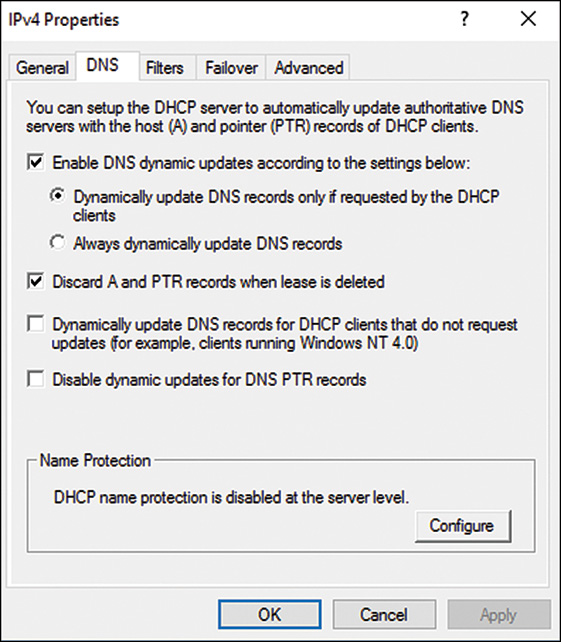
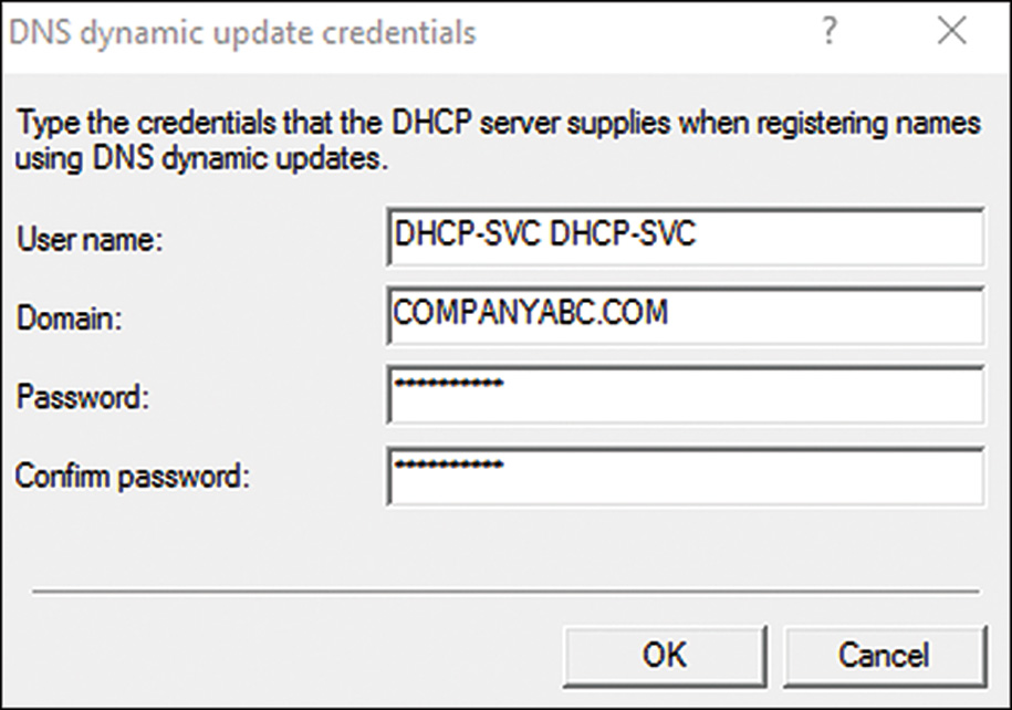
5. Display the Advanced tab and click the Credentials button to open the DNS Dynamic Update Credentials window.
6. Enter the desired service account name, domain, and password. Confirm the password and click OK to validate the credentials, as shown in Figure 10.13.
7. Click OK in the IPv4 windows to complete the changes.
8. Restart the DHCP server service.
This completes the DHCP and DNS dynamic update configuration task.
Access DHCP Activity and Event Logs
Windows Server 2016 includes detailed activity and event logging for the DHCP server service. Historically, reporting or monitoring DHCP usage was quite a challenge, if not impossible. Now DHCP administrators can easily access this data using the built-in logging mechanisms. The DHCP activity log can be read in a text-based editor and is stored in the C:WindowsSystem32DHCP folder. A log is created for each day of the week and named, for example, DHCPSrvLog-Wed.log (for Wednesday). Logs are overwritten each week. The activity log includes startup and shutdown service processing and lease activity. DHCP event logging has also been increased and can be accessed in the Event Viewer. The DHCP event logs include Admin, Operational, and FilterNotifications. These logs are located in the in the Applications and Services/Microsoft/Windows/DHCP-Server node.
Implementing Redundant DHCP Services
As stated earlier in this chapter, DHCP is a critical network service and should be treated as such. Building redundancy into DHCP services has been a challenge for years, and with each release of Windows Server, DHCP redundancy options get better. Windows Server 2016 DHCP server service is no different. The biggest improvement for the DHCP server service is the now built-in failover option, but that is not the only option. The following sections detail historic and current DHCP redundancy options that can be leveraged to improved DHCP reliability.
DHCP Split Scopes
Historically, when administrators required DHCP redundancy, DHCP was deployed on a failover cluster or multiple DHCP servers were deployed with split-scope configuration. A split scope is simply the division of the entire pool of DHCP IP addresses across multiple servers. You can split the scope in various ways, as follows:
![]() 50/50 split-scope configuration—The 50/50 split-scope configuration, as the name indicates, takes half of the DHCP IP address pool, and a scope is created on each server with nonoverlapping addresses. This can work well if both DHCP servers answer at the same time when a DHCP request comes across the network or if some hardware or software load balancer manages the requests. The challenge arises if all or most of the IP addresses will be leased. When a DHCP server configured with only half of the IP addresses is out of leases, that does not stop it from answering DHCP client requests, and clients can end up without an IP address, even if the second server still has available IP addresses for leasing.
50/50 split-scope configuration—The 50/50 split-scope configuration, as the name indicates, takes half of the DHCP IP address pool, and a scope is created on each server with nonoverlapping addresses. This can work well if both DHCP servers answer at the same time when a DHCP request comes across the network or if some hardware or software load balancer manages the requests. The challenge arises if all or most of the IP addresses will be leased. When a DHCP server configured with only half of the IP addresses is out of leases, that does not stop it from answering DHCP client requests, and clients can end up without an IP address, even if the second server still has available IP addresses for leasing.
![]() The 80/20 split-scope configuration—The 80/20 split-scope configuration is the most ideal configuration for Windows Server 2016 and Windows Server 2012 R2 DHCP servers. With the release of Windows Server 2012 R2 and included with Windows Server 2016, DHCP scope settings now allow for a delayed response interval configuration. With an 80/20 split, the server configured with 20% of the addresses is also configured with a delayed response to DHCP client requests. This results in the 20% server becoming more of a backup DHCP server that will be used only in the event of an issue with the primary DHCP server.
The 80/20 split-scope configuration—The 80/20 split-scope configuration is the most ideal configuration for Windows Server 2016 and Windows Server 2012 R2 DHCP servers. With the release of Windows Server 2012 R2 and included with Windows Server 2016, DHCP scope settings now allow for a delayed response interval configuration. With an 80/20 split, the server configured with 20% of the addresses is also configured with a delayed response to DHCP client requests. This results in the 20% server becoming more of a backup DHCP server that will be used only in the event of an issue with the primary DHCP server.
![]() The 100/100 split-scope configuration—The 100/100 split-scope option can be the best configuration, but it requires that 200% of the necessary IP addresses are available to the DHCP IP address pool. For example, if a network will support up to 200 DHCP clients, the DHCP range requires at least 400 IP addresses in the entire DHCP pool. This, of course, is not available in the standard Class C network configuration, so networking changes may be required for this type of configuration to be implemented. With this configuration, no delayed response is required, and clients can get an IP address from either server as required.
The 100/100 split-scope configuration—The 100/100 split-scope option can be the best configuration, but it requires that 200% of the necessary IP addresses are available to the DHCP IP address pool. For example, if a network will support up to 200 DHCP clients, the DHCP range requires at least 400 IP addresses in the entire DHCP pool. This, of course, is not available in the standard Class C network configuration, so networking changes may be required for this type of configuration to be implemented. With this configuration, no delayed response is required, and clients can get an IP address from either server as required.
Windows Server 2016 Delay Configuration Setting
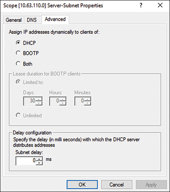
Windows Server 2016 includes a response delay configuration on the DHCP scope settings. This enables administrators to implement redundant DHCP scope configurations across the network, with different version of DHCP servers. To implement a delayed response to a DHCP server on a particular scope, open the scope properties on the desired DHCP server scope and display the Advanced tab. Near the bottom, under Delay Configuration, enter the delay interval in milliseconds and click OK to save the setting, as shown in Figure 10.14. Administrators must test the amount of delay required to get the desired response time from the redundant or secondary DHCP server.
Windows Server 2016 Split Scope Versus Failover
Windows Server 2016 includes a Split-Scope Wizard and a feature called DHCP failover. The Split-Scope Wizard enables administrators to set up a scope across two DHCP servers, including defining the delay configuration, but leases and reservations are not shared or in sync across servers. Furthermore, DHCP clients get a different IP address from each DHCP server the clients obtain leases from. Windows Server 2016 failover is a single DHCP scope configured across two servers. Lease and reservation information is kept in sync across the servers.
DHCP Split-Scope Configuration Wizard
When a split-scope configuration is desired, the DHCP administrator can run the DHCP Split-Scope Wizard to simplify the process. If reservations are already created, the Split-Scope Wizard replicates these reservations, but will not keep these reservations in sync after the split scope is created. To create a split scope across two DHCP servers using the wizard, follow these steps.
1. Install the DHCP server service on at least two DHCP servers and authorize them both.
2. Log on to the primary DHCP server and open the console. Expand the IPv4 node and create the desired scope as outlined previously in this chapter.
3. After the scope is created, right-click the scope in the tree pane and select Advanced and select Split Scope. The DHCP Split-Scope Wizard opens.
4. On the Welcome page of the DHCP Split-Scope Wizard window, click Next to continue.
5. On the Additional DHCP Server page, click the Add Server button to show the list of authorized DHCP servers. Select the desired server or type the name in and click OK to return to the wizard windows.
6. After the additional DHCP server is listed, click Next to continue.
7. On the Percentage of Split page, the default is an 80/20 split, with the 20% going to the additional server. If this is the desired configuration, click Next to continue, as shown in Figure 10.15.
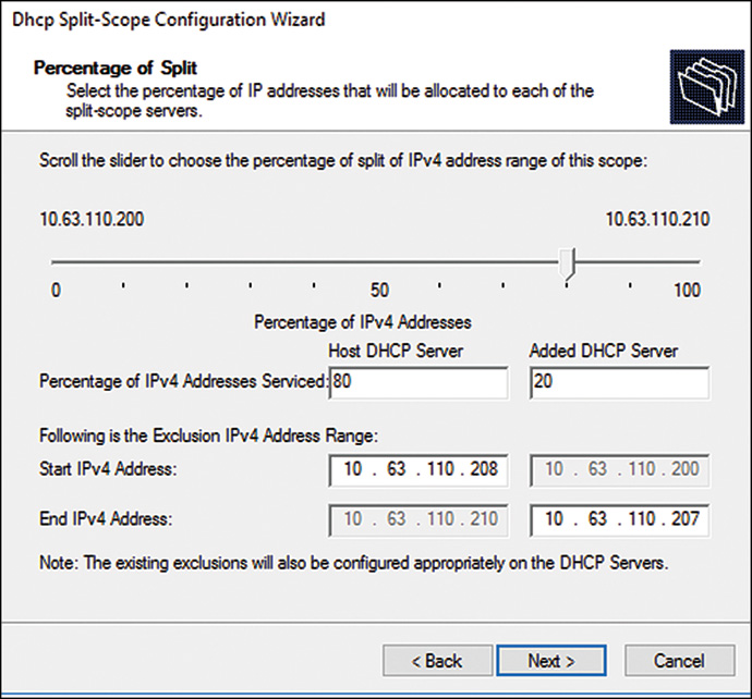
8. On the Delay in DHCP Offer page, enter 0 for the Host DHCP Server and enter the desired delay for the Additional DHCP Server (for example, 200 milliseconds), and then click Next.
9. On the Summary page, review the configuration. If everything looks correct, click Finish to commit the changes and update the scope on both DHCP servers.
10. When the process completes, connect to each of the DHCP servers and verify the scope settings. If the scopes are correct, activate the new scope on the additional DHCP server and on the host DHCP server if not already activated.
This completes the DHCP split-scope configuration task.
Windows Server 2016 DHCP Failover
Windows Server 2016 DHCP includes a failover scope feature. The benefit of this feature is that leases and reservations are synchronized across the DHCP server and a failover cluster is not required. The two different types of failover scopes are a load-balance and hot-standby failover scope. To deploy a failover scope, follow these steps.
1. Install the DHCP server service on at least two DHCP servers and authorize them both.
2. Log on to the primary DHCP server and open the console. Expand the IPv4 node and create the desired scope as outlined previously in this chapter.
3. After the scope is created, right-click the scope in the tree pane and select Configure Failover. The DHCP Configure Failover Wizard opens.
4. On the Introduction page, leave the check box unselected to apply failover to all scopes or uncheck the box and select the desired scopes and click Next to continue.
5. On the next page, type in the name of the partner server for failover and click Next to continue.
6. On the Create a New Failover Relationship page, accept the default name for the failover relationship and configure the desired failover configurations as shown in Figure 10.16. This example configures a 50/50 split-scope load-balanced configuration. This example also uses message authentication, and we enter a shared secret password that must be documented. Click Next to continue.
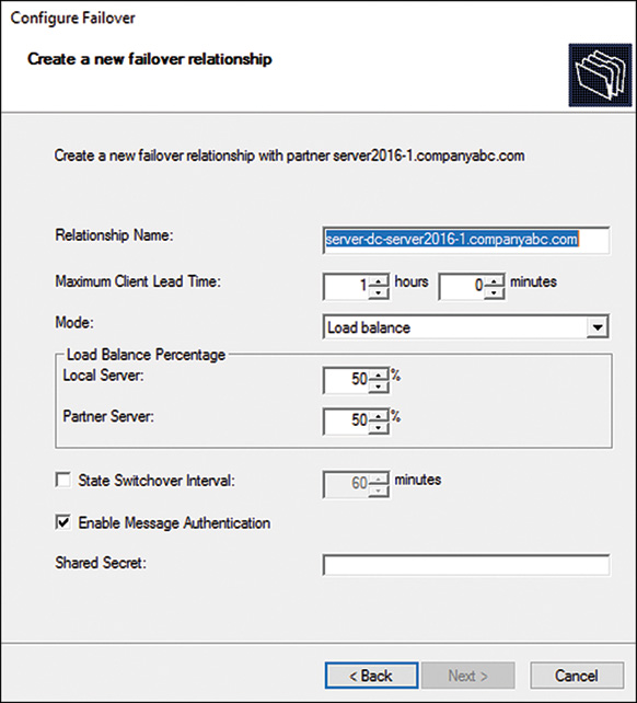
7. On the final page, confirm the configurations. If all the settings look correct, click Finish to create the failover scope.
8. A pop-up window opens to detail the status of the configuration. When the configuration completes successfully, click Close to finish the process.
This completes the failover scope configuration task.
DHCP Failover Cluster Servers
You can deploy DHCP services on a Windows Server 2016 failover cluster. With this type of DHCP deployment, there is only a single DHCP server database, and configuration is not replicated across servers. Instead, the DHCP data is accessed by one server at a time, and when a software or hardware issue is encountered, the DHCP services are moved to another failover cluster host. Deploying services on failover clusters has its own challenges but can prove to be simpler for a DHCP server deployment if the server and storage hardware meets all the failover cluster requirements. For more information about failover clusters, see Chapter 28, “Operational Fault Tolerance (Clustering / Network Load Balancing).”
Exploring Advanced DHCP Concepts
DHCP advanced concepts include functionality not used in everyday situations, such as superscopes, multicast scopes, and delegation of DHCP administration. Also, in today’s computing environment, managing services through a command line environment is highly desired. The following sections cover these advanced DHCP concepts.
Understanding DHCP Superscopes
A DHCP Superscope is a container that can include several DHCP scopes. A Superscope can be created when a single network includes multiple network ranges. For example, if an organization wanted to support different network clients or organizations with a single router, a superscope with multiple scopes configured with different network address spaces could be created. Policies for each scope range could be configured along with reservations to ensure that the desired clients get the right network scope leases when they request a DHCP lease.
Examining DHCP Multicast Scopes
Organizations that require multicast functionality might want to set up DHCP multicast scopes. Multicast clients are used for media and deployment applications where several systems will be accessing the same content. A few examples are operating system deployments or video or audio presentations that each client will access simultaneously. There are special uses for multicast addressing, and DHCP multicast scopes can simplify the setup and delivery in those scenarios.
Delegating Administration of DHCP
Even though DHCP services are quite critical in most networking environments, organizations usually do not dedicate servers specific for this service. DHCP services are usually bundles on servers that host other services. In situations when DHCP administration needs to be delegated to, say, the networking group or a certain administrator, but access to the host server is not desirable, DHCP delegation is the answer. To delegate DHCP administration, first the administrator needs to have access to the DHCP server tools, and those should be installed on the administrator’s IT administrative workstation or on an IT central console server. When the tools are accessible, the IT administrator’s user account, or admin account, can be added to the local DHCP security group named DHCP Administrators.
DHCP Netsh and PowerShell Administration
Like most Microsoft services today, DHCP can be fully managed through a wide array of PowerShell functions and via the Netsh command-line utility. To get a list of the available commands, follow these steps.
1. On a system with the DHCP server tools installed, open a PowerShell console session.
2. Type get-command *DHCP* and press Enter to get the list of all the DHCP-related functions or commandlets.
For example, type get-DHCPServerv4Binding -Computername server10.companyabc.com and press Enter to get the IPv4 address bound to the DHCP server named server10.companyabc.com.
3. To learn how to use any PowerShell function or cmdlet (for example, the getDHCPServerv4Binding function), in the PowerShell window type get-help getDHCPServerv4Binding–Full and press Enter to list the help information.
4. In the same window or in a command prompt window, to access the DHCP Netsh commands, type Netsh DHCP List and press Enter to get a list of the commands available.
5. For example, if the DHCP Post-Install Wizard was skipped or closed, the DHCP administrator can add the security groups for delegation to the local server by using the command Netsh DHCP Add SecurityGroups and pressing Enter.
This completes the overview of some of the DHCP administrative tasks that you can perform using PowerShell commands or Netsh.
Securing DHCP
DHCP by default is an unsecure service and should be treated as such. For example, in a basic DHCP deployment, if a malicious user gains access to the physical network or a wireless network that the DHCP server provides IP addresses leases for, that user can quickly get on the network and begin to try and hack and communicate with the organizations’ systems. Wireless networks get hacked every day, but that is a different topic. Getting access to physical connectivity is less likely, but when it occurs the same risk is presented. This is why every DHCP implementation should include some form of security or frequent auditing. You can secure DHCP services through a number of Windows Server 2016 DHCP server features outlined previously in this chapter, including link-layer filter lists, name protection, and configuring reservations for known systems and creating exclusion ranges that absorb all remaining available IP addresses. The best method by far is a combination of link-layer filter lists and DHCP reservations. For detailed information about link-layer filters or DHCP reservations, see those topics detailed previously in this chapter.
IPv6 Introduction
Internet Protocol version 6 (IPv6) is the updated and revised implementation of the current networking protocol used around the world, IPv4. IPv6 was developed to solve many of the limitations and challenges faced with the IPv4 protocol, initially because of the fast growth of the Internet in the late 1980s and early 1990s and the worry that available addresses would run out. Twenty-plus years ago, the advances in computer networking allowed for huge opportunities for sharing and accessing data between networks, and the Internet Protocol, IPv4, was developed and implemented by the largest Internet service providers (ISPs) that hosted the backbone of the Internet. Organizations, including government institutions, commercial businesses, and schools, started to move their internal networks to this protocol. Although many organizations continued to leverage other networking protocols, if you wanted to share and access data across the Internet, you had to use IPv4. With this big push, operating system development, network-ready applications, and networking devices all included IPv4.
Network administrators had to work hard in some cases to support the quick growth and to troubleshoot issues because IPv4 required manual configuration of addressing on devices and in most cases they also had to deploy and support a method of dynamic addressing provided by, you guessed it, DHCP services. Neither the manual nor automated addressing methods could keep track of all addresses, and administrators had to tightly control and monitor address usage, hence the need for IPAM, covered later in this chapter.
The quick adoption and growth of Internet networking by both private users and businesses began to quickly absorb the usable IP address ranges, and some began to worry that there was a serious risk of running out of IP addresses. When this occurred, private IP ranges were defined, for use on internal networks only, and Network Address Translation (NAT) was developed and leveraged to allow devices on private IP ranges to access the Internet using a shared Internet address. The organizations that used NAT found many uses for this service, mainly managed on routers and firewalls/proxy servers, but in some cases, with certain applications, NAT cannot function at 100%.
Separately, but simultaneously, as organizations moved toward sharing data across the Internet with business partners and between office locations, transmitting data securely over the Internet became a requirement, because supporting private point-to-point lines could not compare on price. Encrypted tunnels, or virtual private networks, were created across the Internet, and this is still in heavy usage today. The use of NAT and VPNs in some earlier implementations proved to be challenging to configure because IPv4 did not have clearly defined or inclusive security standards. Because of this, different hardware and software vendors implemented sometimes similar, but not always compatible versions of IP Security (IPsec). So, for organizations to securely share or securely connect their networks over the Internet, many times they had to use the same vendors for software/hardware or resort to paying for higher-priced private point-to-point connections. As time has passed, IPsec for IPv4 has advanced, and most implementations are compatible, but this IPsec security also comes with more data overhead and utilizes more bandwidth.
Last but certainly not the least, with the daily expanding market of Internet services, transferring of data, and the growing number of users on the Internet, network utilization and IP address assignment are always increasing. Streaming music and peer networking were some of the first types of Internet applications to consume large amounts of bandwidth. Now network utilization and bandwidth requirements are being driven higher and higher by streaming video, social networking, Voice over IP (VoIP) phones, email, Internet browsing and shopping, and the ever-growing number of Internet-capable mobile devices (smartphones, tablets, and even gaming consoles). Many organizations, including Internet and telephone service providers, need a way to prioritize their traffic to ensure that the most business-critical or mission-critical applications have all the bandwidth they require and that the less-important applications, such as those for streaming music, can suffer when mission-critical applications require more throughput.
To support this, IPv4 quality-of-service (QoS) features were implemented on many networks. However, because QoS was not a strict requirement for software and hardware developers to support, many applications do not include enough information in their data packets to sufficiently distinguish their data so that QoS could effectively categorize and prioritize the traffic (thus presenting a challenge to IPv4). For example, QoS in many cases uses the port number, like HTTP 80, to identify web browsing traffic. For an application to work through a web proxy server, the application had to run on port 80 (a music or video streaming application, for example). Therefore, categorizing video as web traffic was incorrect, and the video could get the undesired tier of priority, and this could be a good or bad thing depending on the situation. Although deeper examination into an IPv4 packet allows IPv4 QoS to better prioritize traffic, that can also slow down traffic handling, and when IPsec is used and IPv4 packets are encrypted, QoS cannot do its job properly.
Ah, finally, IPv6 is here! IPv6 has been a work in progress since the early 1990s when it was first named IP Next Generation. Originally, IPv6 was developed to solve the issue of running out of addresses, but now it has grown to also include many features that IPv4 was lacking or needed improvement/guidelines and standardization. Some of the most prominent improvements IPv6 has over IPv4 are as follows:
![]() IP addressing—IPv6 addresses are 128-bit addresses, IPv4 addresses are 32-bit. Although this might seem only four times larger, the actual number of usable addresses as compared is IPv4 2 32 addresses versus IPv6 2 128 addresses.
IP addressing—IPv6 addresses are 128-bit addresses, IPv4 addresses are 32-bit. Although this might seem only four times larger, the actual number of usable addresses as compared is IPv4 2 32 addresses versus IPv6 2 128 addresses.
![]() Automated addressing—IPv4 required manual IP addressing or a DHCP server to provide addressing for newly connected network devices. IPv6 includes both stateful (same as IPv4) and stateless addressing. Stateless addressing can be described as each IPv6 adapter assigns itself a unique address based on discoveries with other neighboring IPv6 stateless devices to enable real automated networking and communication. This self-assigned stateless address is also referred to as the link-local address.
Automated addressing—IPv4 required manual IP addressing or a DHCP server to provide addressing for newly connected network devices. IPv6 includes both stateful (same as IPv4) and stateless addressing. Stateless addressing can be described as each IPv6 adapter assigns itself a unique address based on discoveries with other neighboring IPv6 stateless devices to enable real automated networking and communication. This self-assigned stateless address is also referred to as the link-local address.
![]() Included security—IPv6 includes detailed specifications for IPsec built in to the protocol. This allows each software and hardware vendor to adopt these standards to make securing communication and traffic between different applications and devices simpler and more reliable. Also, the way IPsec has been implemented in IPv6, encrypted data can still be categorized and prioritized properly with QoS, without compromising the security of the data.
Included security—IPv6 includes detailed specifications for IPsec built in to the protocol. This allows each software and hardware vendor to adopt these standards to make securing communication and traffic between different applications and devices simpler and more reliable. Also, the way IPsec has been implemented in IPv6, encrypted data can still be categorized and prioritized properly with QoS, without compromising the security of the data.
![]() Included QoS—The IPv6 header of each packet of data includes two main fields that allow for QoS to perform better than IPv4. These fields, the Traffic Class and Flow Label fields, can be used by software and hardware developers to properly identify their data so that it can be prioritized and routed correctly. The Traffic Class field is used much like the IPv4 header Type of Service (ToS) field, but the Flow Label field is key to quickly identifying a flow or stream of packets, encrypted or not, to allow the entire dataset to be transmitted without examining each packet individually after the first packet is identified.
Included QoS—The IPv6 header of each packet of data includes two main fields that allow for QoS to perform better than IPv4. These fields, the Traffic Class and Flow Label fields, can be used by software and hardware developers to properly identify their data so that it can be prioritized and routed correctly. The Traffic Class field is used much like the IPv4 header Type of Service (ToS) field, but the Flow Label field is key to quickly identifying a flow or stream of packets, encrypted or not, to allow the entire dataset to be transmitted without examining each packet individually after the first packet is identified.
This list identifies just a few of the key improvements of IPv6 over IPv4; there are many more. However, if you are still not convinced that you need to learn IPv6, open a PowerShell console session on a Windows Server 2016 Active Directory domain controller and type Netstat -n and press Enter. This will show you that without a doubt, IPv6 is in use, whether you want to accept it or not. Just look for the IPv6 link-local address, which will start with fe80:: (the link-local prefix). IPv6 addressing is covered next in this chapter, but the remainder of this IPv6 section provides more detailed information about IPv6 and gives you enough information to set up your first IPv6 network.
IPv6 Addressing
Okay folks, get out your scientific calculators. It is time to do some binary, decimal, and hexadecimal conversions. Fun! With the expanded address space associated with IPv6, the developers of IPv6 decided to leverage the hexadecimal numbering system to simplify and reduce the number of characters to identify the IPv6 address. IPv6 addresses are 128 bits in length and much longer than the 32-bit IPv4 address. But before we can dive deeper, the bit count is actually derived from the binary numbering system, which uses only 0s and 1s to represent any number. Binary numbering is also called base-2, because it uses only two numeric values, 0 and 1. Decimal uses base-10 numbering that ranges from 0 to 9, and hexadecimal uses base-16 numbering that ranges from 0 to f, as shown in Table 10.1.
Binary |
Decimal |
Hexadecimal |
Base-2 |
Base-10 |
Base-16 |
0001 |
1 |
1 |
0010 |
2 |
2 |
0011 |
3 |
3 |
0100 |
4 |
4 |
0101 |
5 |
5 |
0110 |
6 |
6 |
0111 |
7 |
7 |
1000 |
8 |
8 |
1001 |
9 |
9 |
1010 |
10 |
a |
1011 |
11 |
b |
1100 |
12 |
c |
1101 |
13 |
d |
1110 |
14 |
e |
1111 |
15 |
f |
11111111 |
255 |
ff |
From our well-known decimal system to convert to and from binary and hexadecimal, you need to learn how to add in each of the three systems. Figure 10.17 shows the representation of 165 in all three systems and may help explain how addition works in each system.

By now, you are probably building a base of information about hexadecimal numbering, and so we will continue with an actual example of an IPv6 IP address.
Network addressing for IPv4 is broken down into four 8-bit groups, totaling 32 bits and divided by periods. Each group can range from 0 to 255 and is represented in three decimal digits, such as the IP address 192.168.101.101. It is common with IPv4 addresses to drop leading 0s. For example, the IP address 192.168.100.010 is normally written as 192.168.100.10. IPv6 addresses, being 128 bits in length, are broken down into eight 16-bit boundaries or groups and are separated by colons. With IPv6 addresses, it is also common to drop leading 0s, but because the addresses are so long, other actions are often taken to shorten the address. The following IPv6 address is written using different forms of character reduction to simplify the notation of the full address, which is listed first:
![]() 2001:0dba:1234:aaaa:0000:0000:3a5f:0456
2001:0dba:1234:aaaa:0000:0000:3a5f:0456
![]() 2001:dba:1234:aaaa:0000:0000:3a5f:456 (leading 0 dropped from last two groups)
2001:dba:1234:aaaa:0000:0000:3a5f:456 (leading 0 dropped from last two groups)
![]() 2001:dba:1234:aaaa:0:0:3a5f:456 (0 groups compressed)
2001:dba:1234:aaaa:0:0:3a5f:456 (0 groups compressed)
![]() 2001:dba:1234:aaaa::3a5f:456 (consecutive 0 groups replaced with ::)
2001:dba:1234:aaaa::3a5f:456 (consecutive 0 groups replaced with ::)
Reducing the address as much as possible is highly preferred and now considered the correct way to notate an IPv6 address. You can find more information about notation standards for IPv6 in RFCs 4291, 5952, and 6052. One important point with character reduction, particularly with 0 groups, is that there can only be one set of double colons; if there happens to be more than one consecutive set of 0 groups, the double colon should be used to compress the larger of the two groups to make the biggest character reduction as possible.
NOTE
The IPv6 network prefix of 2001:db8 has been designated as the range to use for IPv6 documentation examples only as detailed in RFC 3849. Do not use this address range on any production IPv6 deployments.
Comprehending IPv6 Addressing
Learning IPv6 notation can be a bit daunting at first, based not only on the use of hexadecimal numbering, but also on the length of a full address. Using notational abbreviations, as described in RFCs 4291, 5952, and 6052, can assist greatly, but hands-on practice implementing IPv6 addressing and gaining familiarity with binary, decimal, and hexadecimal conversion is key to adopting this new protocol. This section covers addition concepts that network administrators need to know, beyond just the IPv6 address itself.
IPv6 Address Prefix
IPv4 address notation is usually written with a 32-bit network address followed by a forward slash (/) and a trailing number used to delineate the network number and the associated subnet mask. This notation tells the network administrator the range of IP addresses available on that particular network segment. For example, the 192.168.1.0/24 network includes a network number of 192.168.1.0 with a 24-bit subnet mask of 255.255.255.0. To understand what that means, remember that everything goes back to binary, and each binary digit represents 1 bit of the address. Binary addition, which you should become familiar with if you are not already, defines that any number added with 1 will equal 1 and any number added with 0 will equal 0. To understand IP addressing, network administrators need to fully understand these binary addition rules. So, moving forward, the term mask as it relates to IP networking means performing binary addition of a network address with a predetermined bit length of all 1s. For example, a /24 in an 32-bit IPv4 address includes 24 leading 1s and 8 trailing 0s. Table 10.2 shows how binary addition is used on an existing address of 192.168.1.15, with a subnet mask of 255.255.255.0, to derive the network number.
Decimal Address |
Binary IP Address |
|
192.168.1.15 |
11000000.10101000.00000001.00001111 |
Address |
+ 255.255.255.0 |
11111111.11111111.11111111.00000000 |
Subnet mask |
192.168.1.0 |
11000000.10101000.00000001.00000000 |
Network number |
Table 10.2 displays the network number that was derived from addition of the IPv4 address and the associated subnet mask. Although IPv6 has changed the terminology some, this example still applies.
In IPv4, the address is divided into the network number and the host number. In IPv6, the network number portion of the address is referred to as the IPv6 prefix. The IPv6 prefix is written in the same form as for an IPv4 network, but with an IPv6 address followed by a forward slash and a trailing number that is simply referred to as the mask length and written as IPv6address/prefix-length. For example, 2001:dba:1234:5678::/64 translates into a network with a mask of 64 bits, and the IP addresses in this network will all start with the prefix of 2001:dba:1234:5678, followed by four other groups that define the host portion of the address. This example made use of an IPv6 notation reduction that truncated the leading 0 in the second group of dba. This and other notation-reduction practices are covered in the section “IPv6 Address Notation Best Practices,” later in this chapter.
IPv6 DNS Records
Because IPv6 addresses use a completely different number scheme, a new DNS record format was created to support the lookup of IPv6 hosts. The IPv6 forward, or name to IPv6 address type, is an AAAA address type. This address type is available on Microsoft Windows DNS servers and on most other current DNS server systems. For an organization that will leverage IPv6, network and DNS administrators need to ensure that their DNS server system supports this record type. The same goes for the reverse DNS record, where the IPv6 address lookup needs to resolve to a hostname. With Microsoft DNS, the forward lookup zone can support both the standard IPv4 record type of A and the IPv6 record type of AAAA. The reverse DNS zone must be created and populated manually, but even though there will need to be separate reverse DNS zones for IPv4 and IPv6 networks, the reverse DNS records for both are still the same PTR record type. Microsoft clients and servers will, by default, dynamically register their forward and reverse IPv4 addresses in DNS. With IPv6, only the forward DNS records are registered, and if network administrators require IPv6 reverse DNS records, these must be created manually when needed.
IPv6 Address Notation Best Practices
As stated earlier, IPv6 addresses are long, and RFCs have been written to provide standards and best practices for administrators to follow to simplify notation, when possible. Some of the most common IPv6 character-reduction practices are as follows and are all part of what is referred to as 0 compression:
![]() Truncate leading 0s—Whenever possible, remove one or more leading 0s in an IPv6 address group (for example, by changing the IPv6 address of 2001:0dba:0000:0000:0 000:0110:0000:0000 to 2001:dba:0000:0000:0000:110:0000:0000)
Truncate leading 0s—Whenever possible, remove one or more leading 0s in an IPv6 address group (for example, by changing the IPv6 address of 2001:0dba:0000:0000:0 000:0110:0000:0000 to 2001:dba:0000:0000:0000:110:0000:0000)
![]() Compress 0 groups—When an entire group of an IPv6 address is made up of all 0s (for example, 2001:dba:0000:0000:0000:110:0000:0000), the group can be reduced to a single 0 (2001:dba:0:0:0:110:0:0).
Compress 0 groups—When an entire group of an IPv6 address is made up of all 0s (for example, 2001:dba:0000:0000:0000:110:0000:0000), the group can be reduced to a single 0 (2001:dba:0:0:0:110:0:0).
![]() Replace consecutive zero groups with double colon—When consecutive 0 groups are encountered, as shown in the previous example, two or more groups can be replaced with a double colon.
Replace consecutive zero groups with double colon—When consecutive 0 groups are encountered, as shown in the previous example, two or more groups can be replaced with a double colon.
![]() Only one set of double colons can be used in an IPv6 address.
Only one set of double colons can be used in an IPv6 address.
![]() When there is more than one set of zero groups in an IPv6 address, the double colon should be used to replace the largest set. For this example, that is the last three groups of 0s; the IPv6 address is then written as 2001:dba::110:0:0.
When there is more than one set of zero groups in an IPv6 address, the double colon should be used to replace the largest set. For this example, that is the last three groups of 0s; the IPv6 address is then written as 2001:dba::110:0:0.
![]() When multiple consecutive groups of 0s are replaced with a double colon, administrators can subtract the remaining number of groups from 8 to determine how many groups of 0s were removed. In this case, 8–5 = 3, so the double colon has replaced three groups of consecutive 0s.
When multiple consecutive groups of 0s are replaced with a double colon, administrators can subtract the remaining number of groups from 8 to determine how many groups of 0s were removed. In this case, 8–5 = 3, so the double colon has replaced three groups of consecutive 0s.
![]() Do not remove trailing or 0s between other numbers—When a group contains a 0 that is surrounded by other numbers or is the last number in a group, it needs to remain as part of the final address. For example, in the sixth group (originally 0110), removing the trailing 0 would change the number and therefor change the address. This might seem obvious, but with all the available options to reduce the address, it is important to note this rule.
Do not remove trailing or 0s between other numbers—When a group contains a 0 that is surrounded by other numbers or is the last number in a group, it needs to remain as part of the final address. For example, in the sixth group (originally 0110), removing the trailing 0 would change the number and therefor change the address. This might seem obvious, but with all the available options to reduce the address, it is important to note this rule.
So with all the options previously noted for 0 compression, the original address of 2001:0dba:0000:0000:0000:0110:0000:0000 is now reduced to 2001:dba::110:0:0, and this reduces the original 39 character address to 17 characters (including colons).
One more important point about address notation is that although it is not a standard, a good practice for IPv6 notation is to use all lowercase letters.
IPv6 Addresses and Port Specification
In many documentation cases, it is necessary to also designate the port of a service running on IPv6. IPv4 uses a colon to designate the port (for example, 192.168.1.15:80), but with IPv6 this would cause a lot of confusion. To designate an IPv6 and a port address, you can enclose the address in brackets followed by the colon and port number (for example, [2001:dba::110:0:0]:80); 2001:dba::110:0:0 port 80 is also acceptable.
Unique Local Address
As with IPv4, many organization use the designated IPv4 private IP address ranges of 10.0.0.0/8, 172.16.0.0/16, and 192.168.0.0/24. With IPv6, because there are enough addresses, organizations may not need to use private addressing with NAT at the router or perimeter firewall. Organizations may start to use globally routable IPv6 addresses, or addresses that can be used on the internal network and on the Internet. However, many network administrators may opt to start IPv6 implementations using an internal-use IPv6 address known as the unique local address (ULA). This the IPv6 counterpart to the IPv4 private IP ranges and is detailed in RFC 4193. The ULA prefix is fc00::/7. The addresses within this range are intended to be used on internal site networks, and can even be used to route between internal networks, but are not intended to be routed globally or on the Internet.
The fc00::/7 prefix is divided further into two /8 address prefixes, including fd00:/8, which should be used for actual network deployments and has the eighth bit set to 1, indicating a local network, followed by a randomly generated 40-bit string, known as the global ID and a 16-bit subnet ID allowing network administrators a standard for addressing devices on /64 subnets. The other network is fc00:/8 and has the eighth bit set to 0, but that network has not yet been clearly defined or accepted as a standard. One network range from the fd00::/8 prefix is the fe80::/64 prefix, which is used for link-local addresses. The link-local address is the self-generated address assigned on every IPv6-enabled adapter. This link-local address can be used between IPv6 devices that were not statically configured with an address and did not receive an address from an IPv6 DHCP server (that is, the stateless configuration IPv6 address).
IPv6 Transition Technologies
Today, the Internet (and the world) is mostly running on IPv4 networks. As more and more operating system and devices natively support IPv6, and even require it, making IPv6 work globally will quickly become necessary. Because IPv4 and IPv6 devices cannot natively communicate with one another, protocols have been developed to bridge the gap, and these are known as the IPv6 transition technologies.
Before discussing transition technologies, or how we can make IPv6 devices communicate with IPv4 devices, we need to examine the different types of nodes on the networks, as defined in RFC 2893:
![]() IPv4-only node—This type of nodes uses IPv4 only and most likely does not even have the IPv6 protocol installed. This is Windows XP and Windows Server 2003 and earlier, by default, but IPv6 can be installed and configured on these operating systems.
IPv4-only node—This type of nodes uses IPv4 only and most likely does not even have the IPv6 protocol installed. This is Windows XP and Windows Server 2003 and earlier, by default, but IPv6 can be installed and configured on these operating systems.
![]() IPv6/IPv4 node—This is the typical node today, which has both IPv4 and IPv6 protocols installed and uses both protocols. Windows Vista, Windows Server 2008, and later client and server operating systems are IPv6/IPv4 nodes.
IPv6/IPv4 node—This is the typical node today, which has both IPv4 and IPv6 protocols installed and uses both protocols. Windows Vista, Windows Server 2008, and later client and server operating systems are IPv6/IPv4 nodes.
![]() IPv6-only node—A node that only has the IPv6 protocol installed and in use. In today’s world, finding a node that fits this description is nearly impossible.
IPv6-only node—A node that only has the IPv6 protocol installed and in use. In today’s world, finding a node that fits this description is nearly impossible.
![]() IPv6 node—A node that uses IPv6, regardless of whether IPv4 is also used. This is a more generic term.
IPv6 node—A node that uses IPv6, regardless of whether IPv4 is also used. This is a more generic term.
![]() IPv4 node—A node that uses IPv4, regardless of whether IPv6 is also used. This is a more generic term.
IPv4 node—A node that uses IPv4, regardless of whether IPv6 is also used. This is a more generic term.
Communication between IPv4 and IPv6 devices does not directly occur. Devices need to communicate using the same protocol. You can enable IPv6 devices to communicate over IPv4 networks, but when IPv6/IPv4 nodes are in use on the same network and properly addressed, they use transition technologies built in to the protocol stack architectures. Windows XP and Windows Server 2003 use the dual stack, and later operating systems (Windows Vista and Windows Server 2008 and later) leverage the dual layer. With the dual stack, when data is prepared for the network, it is prepared for both protocols separately, requiring more overhead within the operating system. With the dual layer, the upper-stack layers are shared, thus reducing overhead, and that is the architecture in use with the more recent operating systems. Future releases will most likely do away with the dual layer and move toward an IPv6-only stack. Figure 10.18 compares the dual stack and dual layer architectures.
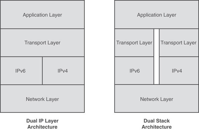
IPv6 Tunneling
When IPv6 nodes are separated between IPv4 networks, they cannot directly communicate. To bridge the gap, the IPv6 nodes can tunnel through the IPv4 network. This tunneling can occur on the host itself or through a designated IPv6 tunneling router. When IPv6 is tunneled through an IPv4 network, the IPv6 packet is encapsulated within an IPv4 packet. Figure 10.19 shows an example of an encapsulated header.
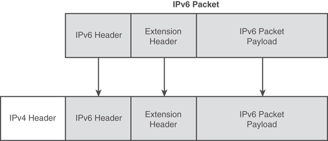
There are two different IPv6 tunnel configurations. The first is a configured tunnel, in which the endpoints and static routes for IPv6 traffic through an IPv4 network are defined. The second is an automatic tunnel that is created based on the IPv4 address of the device. The automatic tunnel can be leveraged only on devices that are properly configured to use both IPv6 and the IPv4. Configured tunnels, although these can be created on local windows hosts, can also be configured on designated routers to bridge the gap between IPv6-only devices on different networks separated by IPv4 networks.
The ISATAP Tunneling Protocol
The Intra-Site Automatic Tunnel Addressing Protocol (ISATAP) is an IPv6 transition technology used to allow administrators to deploy IPv6 nodes on IPv4 networks. For ISATAP to be used, an ISATAP router must be deployed and have a DNS record on the local network. ISATAP is not intended for use across the Internet (hence the user of intra-site as part of its name), but ISATAP traffic must traverse an ISATAP router to allow an IPv6-only host to communicate with IPv4 devices. The two main requirements for an ISATAP network to function are an ISATAP router and, of course, ISATAP hosts:
![]() ISATAP router—An ISATAP router advertises subnet prefixes assigned to the ISATAP network, to ISATAP hosts, and the router forwards packets between the IPv4 and IPv6 network.
ISATAP router—An ISATAP router advertises subnet prefixes assigned to the ISATAP network, to ISATAP hosts, and the router forwards packets between the IPv4 and IPv6 network.
![]() ISATAP hosts—ISATAP hosts can communicate directly with ISATAP and IPv6 hosts on the local network and with IPv4 hosts through the ISATAP router.
ISATAP hosts—ISATAP hosts can communicate directly with ISATAP and IPv6 hosts on the local network and with IPv4 hosts through the ISATAP router.
ISATAP addresses are automatically assigned or created on ISATAP hosts, but before that occurs an ISATAP router must be detected by a potential host. A router is detected when a host can resolve the name ISATAP with a DNS lookup within their primary DNS suffix, or through another form of short-name resolution. When an ISATAP router is detected, an address is constructed based on the address prefix provided by the ISATAP router, concatenated with the local IP address of the ISATAP host. The ISATAP address is constructed of the 64-bit IPv6 prefix already defined for the IPv6 network followed by a 32-bit ISATAP designation and then by the 32-bit IPv4 address. For example, with an IPv6 prefix of 2001:0dba:1234:5678::/64 for a host with an IPv4 address in a private network range, the address is as follows:
2001:0dba:1234:5678:0:5efe:w.x.y.z, where the w.x.y.z represents the IPv4 address
The 6to4 Tunneling Protocol
The 6to4 tunneling protocol provides automatic address assignment and tunneling of IPv6 traffic across the IPv4 Internet. This is mainly used when the host or client is connected directly and assigned a public IPv4 Internet address, but can also be used when a host has an IPv4 private address assigned. The 6to4 address format uses an IPv6 global prefix because it is an IPv6 prefix that is okay to route across the Internet. Figure 10.20 shows the 6to4 address format.
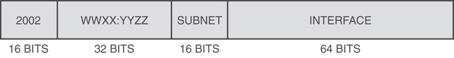
A 6to4 global address prefix is in the format of 2002:WWXX:YYZZ::/48, where WWXX:YYZZ is the hexadecimal representation of the public IP address. Each of the two letters represents one of the 32-bit IPv4 octets. As an example of a 6to4 address converted, a public IP address of 72.34.113.11 is converted to 2002:4822:710b::/48.
The 6to4 network can include the following components:
![]() 6to4 host—A host that has both IPv4 and IPv6 and is configured with a 6to4 address in the IPv6 global address range of 2002::/16.
6to4 host—A host that has both IPv4 and IPv6 and is configured with a 6to4 address in the IPv6 global address range of 2002::/16.
![]() 6to4 router—An IPv6/IPv4 forwards traffic between 6to4 hosts on the local network to other 6to4 routers and to 6to4 relay routers.
6to4 router—An IPv6/IPv4 forwards traffic between 6to4 hosts on the local network to other 6to4 routers and to 6to4 relay routers.
![]() 6to4 relay—Forwards 6to4 traffic between the IPv4 Internet and IPv6-only devices directly connected to the Internet.
6to4 relay—Forwards 6to4 traffic between the IPv4 Internet and IPv6-only devices directly connected to the Internet.
The Teredo Tunneling Protocol
The Teredo IPv6 transition technology is commonly used when the client system is assigned a private IP address and a 6to4 network is not enabled or preferred. One of the biggest advantages of Teredo over 6to4 is that 6to4 is not so NAT friendly when traversing the Internet and each endpoint needs to have a public IPv4 address. Also, 6to4 traffic has a reasonably high failure rate because the packets are encapsulated and marked with protocol field 41, which is unknown to many firewalls, and unknown protocols are usually blocked by default. Also, using the public Internet, end users cannot control how many NAT traversals (NAT-T) the packets must go through from the sources to the destination, making 6to4 not so resilient to support routing through NATs. This is where Teredo (IPv6 NAT-T) becomes the preferred tunneling protocol. RFC 4380 describes the Teredo tunneling protocol. Teredo makes its way around the NAT challenge by changing the way the IPv6 packet is encapsulated. With the ISATAP and 6to4 tunneling protocols, the IPv6 packet is encapsulated within an IPv4 packet, and the header IP protocol field is set to a value of 41 to identify tunneled traffic. Teredo tunnels Ipv6 over Ipv4 differently as the IPv6 packet are encapsulated and sent within an IPv4 User Datagram Protocol (UDP) packet that easily gets through NAT traversals. But, the Teredo protocol is considered the protocol of last resort, mainly because of the high overhead associated with the encapsulation mechanism, but also because of security concerns. Teredo basically allows hosts to directly traverse NATs to communicate across the Internet with other Teredo hosts using what is referred to as open-ended tunnels. Because of the way the Teredo protocol encapsulates Ipv6 traffic within Ipv4 UDP packets, it can essentially bypass some of the strict traffic inspection performed by network firewalls and intrusion prevention system (IPS). This leaves the burden of validating the Ipv6 traffic to the Teredo host receiving the data. This might not be the most secure or ideal scenario, and in cases where Teredo must be used, network administrators should fully understand Teredo security risks and how to mitigate them.
Until a true IPv6 Internet is configured, there will be security and functionality challenges to make IPv6 work on both the internal network and across the Internet. In some ways, having the transition technologies in place slows down the larger ISPs’ adoption of an Ipv6 Internet.
Configuring IPv6 on Windows Server 2016
To begin using IPv6 on your organization’s internal network, deploying a DHCP server and manually configuring IP addresses on servers and network devices is a good place to start. A few things to consider when designing your IPv6 network include selecting the IPv6 prefixes for local and remote sites, and determining how clients will be assigned addresses (DHCP or manually) and how or if you will route IPv6 traffic between sites and how IPv6 hostnames will be resolved. A simple IPv6 implementation consists of static or manually configured IPv6 addresses on servers and network devices, an IPv6 DHCP server for client workstations, an IPv6 DNS reverse lookup zone, and IPv6 subnet definitions in Active Directory for each of your IPv6 networks. With these simple steps, you will be well on your way to implementing and using IPv6 on the local network. This simple network design is the basis for the following sections about implementing IPv6 services.
Creating an IPv6 Subnet in Active Directory
For Active Directory clients to properly associate their local services with their respective Active Directory site, all the subnets need to be added to the Active Directory site configuration, and this applies to both IPv4 and IPv6 networks. For this example, we use the documentation IPv6 prefix 2001:dba::/64, but for a real-world implementation a network administrator should design the IPv6 network using a prefix within the ULA range described earlier in this chapter. For our network, the IPv4 network is 192.168.206.0/24, and we will use the IPv6 prefix 2001:dba:ce::/64. To create the IPv6 subnet in the default Active Directory site, follow these steps:
1. Log on to the domain controller.
2. Click the Server Manager tile on the taskbar.
3. Click the AD DS link in the tree pane on the left.
4. In the Servers pane, right-click the domain controller and select Active Directory Sites and Services, as shown in Figure 10.21.
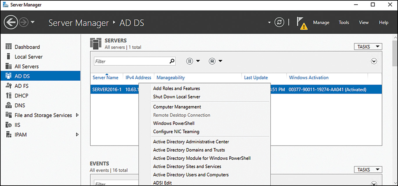
5. When the active Directory Sites and Services console open, expand the Sites nodes in the tree pane and select Subnets.
6. Right-click the Subnet node and select New Subnet.
7. When the New Object–Subnet window opens, in the Prefix field, type in your IPv6 network prefix and then select the associated site to associate it with, as shown in Figure 10.22. Click OK to create the subnet.

8. Close the Active Directory Sites and Subnet console.
Manually Setting the IPv6 Address on Windows Server 2016
Manually configuring an IPv6 address on a Windows Server 2016 system is nearly the same process as configuring IPv4 and is pretty simple. For this example, we use the documentation IPv6 prefix 2001:dba::/64, but for a real-world implementation a network administrator should design the IPv6 network using a prefix within the ULA range. For our network, the IPv4 range is 192.168.206.0/24, and for the IPv6 to provide some easy-to-remember addressing, we will use 2001:dba:ce::/64. The server in this example has an IPv4 address of 192.168.206.31, and its corresponding IPv6 address will be 2001:dba:ce::1f/64. To configure the address, follow these steps:
1. Log on to the proposed IPv6 server.
2. Click the Server Manager tile on the taskbar.
3. Click the Local Server link in the tree pane on the left.
4. Click the link to the right of the Wired Ethernet Connection in the Properties section, as shown in Figure 10.23.
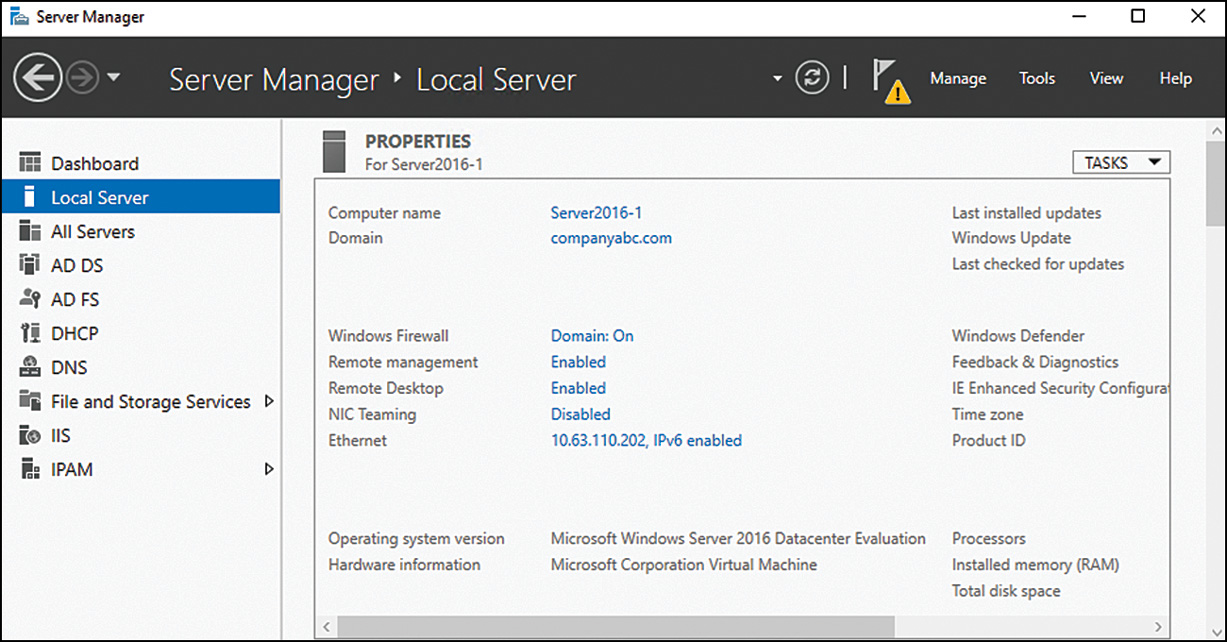
5. When the Network Connections window opens, right-click the Ethernet Connection and select Properties.
6. Scroll down and select Internet Protocol Version 6 (TCP/IPv6) and click the Properties button.
7. In the Internet Protocol Version 6 (TCP/IPv6) Properties window, select the Use the Following IPv6 Address radio button and type in the desired address. When finished, press the Tab key to autopopulate the subnet prefix length of 64.
8. For this example, there is no IPv6 router, so leave that field blank, but enter the IPv6 address of the appropriate DNS server (in this case, the local DNS DC system, as shown in Figure 10.24).
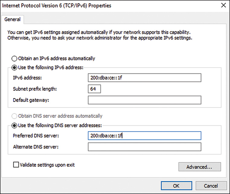
9. Click OK and then click Close to apply the new address and save the configuration to the network connection. Because this is on the DNS server, the DNS service automatically binds to this new IPv6 address, and the network connection dynamically registers the new IPv6 Quad A Record (AAAA) record in the forward DNS lookup zone.
10. Close the Network Connections window.
Creating IPv6 DNS Records and Zones
A Windows Server 2016 DNS server automatically supports IPv6 DNS records. The forward record is the AAAA record, and the reverse is still just a PTR record. When a Windows Server 2016 DNS server is assigned a static IPv6 address, it supports DNS services on this address by default. Also, when the forward DNS zone for the domain is created, AAAA records can be dynamically or statically added to the forward zone without any necessary changes. IPv6 hosts will be able to dynamically register AAAA records immediately. To support IUPv6 reverse DNS lookup, follow the proceeding steps to create the IPv6 reverse DNS zone.
1. Log on to the DNS server.
2. Click the Server Manager tile on the taskbar.
3. Click the DNS link in the tree pane on the left.
4. In the Servers pane, right-click the DNS Server and select DNS Manager from the list.
5. When the DNS Manager console opens, expand the DNS server to reveal the forward and reverse lookup zones.
6. Expand the Forward Lookup Zones node and select the zone for the Active Directory domain to load the records list in the right pane. Scroll up and down to view the existing A and AAAA records, which should already be present for the DNS/DC server.
7. Before we create a new AAAA record, an IPv6 reverse DNS zone should be created. Select and Expand the Reverse Lookup Zones node to reveal the list of existing zones. Right-click the node and select New Zone.
8. Click Next on the Welcome page.
9. On the Zone Type page, accept the defaults of a Primary zone that is stored in Active Directory, and then click Next.
10. On the Active Directory Zone Replication Scope page, accept the defaults and click Next.
11. On the Reverse Lookup Zone Name page, select the IPv6 Reverse Lookup Zone radio button and click Next.
12. On the Reverse Lookup Zone Name page, type 2001:dba:ce::/64 and the zone name will be automatically created based on a four group, 64-bit prefix of 2001:0dba:00ce:0000. Accept the name and click Next.
13. On the Dynamic Updates page, accept the defaults and click Next.
14. On the Completing the New Zone Wizard page, click Finish to complete the process.
15. Now back in the DNS Manager console window, select and expand the new IPv6 reverse zone in the tree pane to load the list of records.
16. Right-click the new IPv6 reverse DNS zone and select New Pointer (PTR) to create a new reverse record for the DNS/DC server.
17. In the New Resource Record window, the 64-bit prefix will be autopopulated. To define the new record, you can either enter the full IPv6 address with no 0 compression or, if the forward AAAA record is created, click the Browse button and search in the forward lookup zone for the corresponding record and select it. This will populate the IPv6 address, as shown in Figure 10.25. Click Next to complete the record creation.
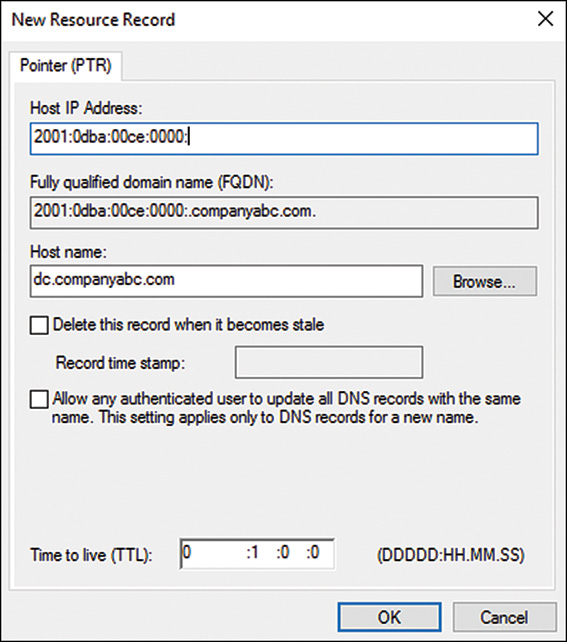
One important point to remember is that a Windows Server 2016 system, or any IPv6-configured Windows system, will not dynamically register reverse IPv6 records. This is by design and may be changed in the future. But for now, if you require IPv6 reverse DNS resolution, the records will need to be created manually.
Setting Up Windows Server 2016 DHCP IPv6 Scopes
To support stateful IPv6 with DHCP, the network administrator can create IPv6 DHCP scopes on a Windows Server 2016 DHCP server. To create a new IPv6 DHCP scope, follow these steps:
1. Open the DHCP console and connect to the desired DHCP server.
2. When the DHCP Manager console opens, expand the DHCP server to reveal the IPv4 and IPv6 nodes.
3. Select and expand the IPv6 node, right-click the node, and select New Scope.
4. Click Next on the Welcome page.
5. On the Scope Name page, enter a name and description for the scope and click Next.
6. On the Scope Prefix page, enter the scope prefix and leave the default of 0 for the preference. For our example, we use 2001:dba:ce::/64 as the prefix and 0 for the preference. Click Next to continue.
7. On the Add Exclusions page, you need to define the IP addresses that will not be included in this larger DHCP scope range and then click Add. For this example, we retain 255 addresses for statically configured devices and leave the remainder for the DHCP scope. Figure 10.26 shows the exclusion range we define.
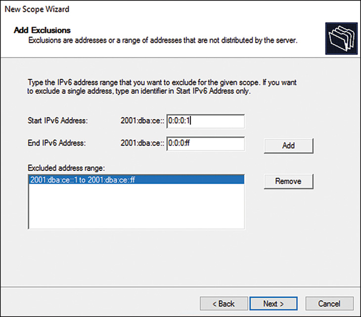
8. On the Scope Lease page, enter the desired time frame for an IPv6 address to be leased and click Next. There are two different entries here: preferred lifetime and valid lifetime. The valid lifetime is when the DHCP server considers an IP address available to be leased again. The preferred lifetime is what is given to the device as the time it should renew the lease by. Leave the defaults, but if you must change them, ensure that the valid lifetime duration is longer than the preferred.
9. On the Completing the New Scope Wizard page, select the desired radio button to activate the scope and click Finish to create the scope.
If necessary, you can create DHCP scope options for the IPv6 scope using the DHCP console after the scope is created. This completes the creation of the DHCP IPv6 scope.
IP Address Management
The IP Address Management (IPAM) feature included with Windows Server 2016 provides network administrators with a single centralized console from which they can view and manage the IP addresses of the entire enterprise. This feature is new to Microsoft Windows servers, but is not new to network administration. Before Windows Server 2016, network administrators had to manage and keep track of IP addresses using a combination of tools such as DHCP Manager and DNS Manager, in addition to third-party products that may have tracked client IP addresses. Commonly, detailed spreadsheets or proprietary databases were created to provide a source that could be referenced when a new device needed addressing or when an audit of an IP address was required. The challenge, however, was that no one place could be reviewed to get the latest and most correct information because keeping the different sources of data in sync and up-to-date was just not reliable enough.
Windows Server 2016 IPAM Server enables network administrators to leverage a built-in product supported by Microsoft that can help reduce or even eliminate the need for manual import or synchronization of IP address data from multiple sources. IPAM can be used to collect and present IP address data from DNS, DHCP, NPS, and domain controllers in a single centralized console. Furthermore, through the Server Manager-integrated IPAM console, network administrators can even manage those services to a degree, and when deeper management is required, the Server Manager console can quickly be used to launch the desired management console for the particular service.
As networks grow, centralized administration is always at the heart of a well-performing and simplified managed infrastructure. The task of managing and tracking IP addresses and networks is no different, and the IPAM feature provides views and functionality for IPAM not included in any other Microsoft role or feature.
IP Address Tracking Today
For IP address auditing or tracking, when a live network IP address needs to be linked or associated with a device, network administrators can use tools such as Nslookup to do a PTR reverse IP-to-name lookup and comb WINS databases or even use ping -a. Further testing can even include trying to connect to that system using various techniques like the Computer Management console, Telnet, HTTP, or any other means (such as reviewing firewall logs and so forth). All in all, this task can take some time and might not even produce the correct result; the administrator might have to physically searching that system using network switch ports, the Address Resolution Protocol (ARP) cache, or even tracing network ports to wall jacks and using a wall jack map to find the device. If this seems unrealistic to you, well, it’s not, and it happens every day with network and security teams.
Consider a different scenario where we need to determine which device was assigned and used a DHCP assigned IP a week ago and that is now leased to a different system. How could we easily perform that task? The only way to do this before was to comb the DHCP activity logs, and if you didn’t catch it within a week, you had to look through backups or shadow copies of that file. The DHCP activity logs are located on the local DHCP server in the default location of C:WindowsSystem32DHCP and are named DhcpSrvLog-Mon.log and DhcpV6SrvLog-Mon.log (for instance). The daily logs are overwritten each week.
Installing the IPAM Server and Client Features
Deploying IPAM into the network requires several steps. Planning the IPAM infrastructure is not a difficult task, but you must consider which systems will be managed by IPAM, how these systems will be configured to support IPAM, who will be able to view the IPAM information, and who will be able to make changes to IPAM-managed servers. Well, maybe it’s not such as simple task from a design standpoint, but in reality, the concept of IPAM will not be new to organizations. So, as always, careful planning makes for the best deployment. The overall planning consists of a few main areas:
![]() Discovery and server management—How servers will be located and added to the IPAM console. After a server is discovered or added manually, it still needs to be enabled in the IPAM console before it can be monitored and managed by IPAM.
Discovery and server management—How servers will be located and added to the IPAM console. After a server is discovered or added manually, it still needs to be enabled in the IPAM console before it can be monitored and managed by IPAM.
![]() Provisioning—How managed servers will be configured to support IPAM data discovery and remote management. There are several configuration changes that will need to be implemented on a managed server before IPAM can collect data and, as possible, manage the service. This can occur manually or through group policy, and this process is known as provisioning.
Provisioning—How managed servers will be configured to support IPAM data discovery and remote management. There are several configuration changes that will need to be implemented on a managed server before IPAM can collect data and, as possible, manage the service. This can occur manually or through group policy, and this process is known as provisioning.
![]() Task management—IPAM contains several tasks that are used to discover servers on the network and periodically collect activity, usage, and audit data and perform data maintenance and cleanup. IPAM administrators need to be familiar with task management both manually and through the scheduling to adjust the tasks to fit the organization’s data collection and cleanup design.
Task management—IPAM contains several tasks that are used to discover servers on the network and periodically collect activity, usage, and audit data and perform data maintenance and cleanup. IPAM administrators need to be familiar with task management both manually and through the scheduling to adjust the tasks to fit the organization’s data collection and cleanup design.
![]() Data sources—IPAM can collect and organize data from several sources, including text files that can be imported manually by the IPAM administrator and, of course, DNS, DHCP, DC, and NPS servers. IPAM administrators need to understand how to import data manually and how to add and provision new servers to allow IPAM tasks to collect the data automatically.
Data sources—IPAM can collect and organize data from several sources, including text files that can be imported manually by the IPAM administrator and, of course, DNS, DHCP, DC, and NPS servers. IPAM administrators need to understand how to import data manually and how to add and provision new servers to allow IPAM tasks to collect the data automatically.
![]() IP address data presentation—The IPAM console provides administrators with a few different ways to search and present IP address datasets. Administrators can change the view and add or remove columns and even export to CSV files.
IP address data presentation—The IPAM console provides administrators with a few different ways to search and present IP address datasets. Administrators can change the view and add or remove columns and even export to CSV files.
![]() Security and permissions—IPAM contains several security groups, and these groups are granted different levels of permissions, not only within the IPAM console, but also on the managed servers.
Security and permissions—IPAM contains several security groups, and these groups are granted different levels of permissions, not only within the IPAM console, but also on the managed servers.
The IPAM server must be installed on a member server and should not be attempted on a domain controller. Also, when IPAM is installed on a DHCP server, the server discovery process does not function correctly and is not recommended. IPAM servers should be deployed on dedicated member server systems or at least on systems that do not include any of the ADDS, DHCP, DNS, or NPS roles. To install the IPAM server and client tools, follow these steps:
1. Log on to the IPAM server.
2. Click the Server Manager tile on the taskbar.
3. Click the Dashboard link in the tree pane and select Add Roles and Features to invoke the Add Roles and Features Wizard.
4. On the Before You Begin page, in the Add Roles and Features Wizard, click Next to continue.
5. On the Select Installation Type page, select the Role-Based or Feature-Based Installation radio button and click Next to continue.
6. On the Select Destination Server page, select the Select a Server from the Server Pool radio button and select the local server in the window. Click Next to continue.
7. On the Select Server Roles page, do not check any check boxes. Click Next to continue.
8. On the Select Features page, scroll down to IP Address Management (IPAM) Server Feature and check it. A pop-up window opens showing all the dependencies, including the IPAM client Feature Administration Tool, as shown in Figure 10.27. Click Add Features in the pop-up window, and then click Next on the Select Features page to continue.
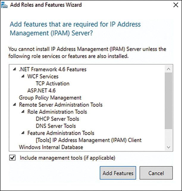
9. On the Confirm Installation Selections page, review the list and click Install to begin the installation.
10. When the installation completes, click Close to return to the Server Manager window.
After the installation of the server feature and client tools, you must complete several steps before you can use IPAM, as follows:
1. Connect to the IPAM server.
2. Configure IPAM server provisioning.
3. Configure servers for IPAM management.
4. Configure and run server discovery.
5. Define discovered servers as IPAM managed.
6. Define IP address blocks.
7. Collect server data.
Connecting to the IPAM Server
When the IPAM client tools are also installed as part of the IPAM server installation, the IPAM server can be managed from Server Manager. To manage the IPAM server on the local system, follow these steps:
1. Log on to the IPAM server.
2. Click the Server Manager tile on the taskbar.
3. Click the IPAM link in the tree pane to display the IPAM console.
The center console shows a list of six tasks, and the first is Connect to an IPAM Server. This should show that the console is already connected to the local system.
4. For remote administration of an IPAM server, you must perform two steps: install the IPAM client, and add a known IPAM server to the Server Manager server pool. After you complete these tasks, IPAM shows in the tree pane. To connect the IPAM server, select IPAM and then click Connect to IPAM Server.
5. When the Connect to IPAM Server window opens, select the IPAM server in the list and click OK.
NOTE
When the IPAM client is installed on a system that is not the IPAM server, the Group Policy Management Console and the DHCP and DNS tools are also installed; Active Directory tools are not.
Configuring IPAM Server Provisioning
After the IPAM client is installed and the console is connected to the desired IPAM server, IPAM provisioning should be performed.
Servers that will be monitored and managed by an IPAM server need to be configured so that the IPAM server can connect to its services for data collection and service management. Servers can be configured to support the IPAM server either manually or through group policy. There are several configurations that need to occur on a server that will be managed by an IPAM server, including adding firewall rules, adding security groups to local server and service permissions, and sharing folders for remote IPAM server access. These steps can be manually performed on each server. Servers such as DHCP, DNS, ADDS, and NPS are configured differently, and if many servers require configuration, this can take quite a while.
IPAM server provisioning creates the IPAM database on the IPAM server and defines whether managed servers will be configured manually by the server administrator or through a set of group policies with a specifically defined group policy object (GPO) prefix name. As part of the IPAM provisioning process, local security groups are created, as is a domain security group named IPAMUG, which the local IPAM server is made a member of. This domainIPAMUG security group is primarily used to grant permission on managed servers, as outlined in the next section.
When configured for manual provisioning, an IPAM server will do nothing when a server is added to the IPAM server as a managed server. When configured for group policy provisioning, the IPAM server, using the logged-in administrator credentials, searches for an existing group policy with the correct name and adds the managed server to the security filtering list. For now, all you need to know is whether your managed servers will be configured manually or through group policy. The IPAM provisioning process gets the IPAM server ready by creating and configuring the IPAM database, local security groups, and IPAM tasks on the local server. The provisioning process does not create any group policies in the domain, regardless of which provisioning method is selected. One thing to keep in mind is that after the provisioning wizard is run, the method of provisioning cannot be changed. To configure provisioning on an IPAM server, follow these steps:
1. Log on to the IPAM server or a server with the IPAM client tools installed and the IPAM server added to the server pool in Server Manager.
2. Click the Server Manager tile on the taskbar.
3. Click the IPAM link in the tree pane to display the IPAM.
4. The IPAM console shows a list of six tasks, and the first is Connect to an IPAM Server. If the console does not indicate that it is connected to an IPAM server, click this first task and follow the steps detailed in the previous section to connect to the desired IPAM server.
5. In the IPAM console, click Provision the IPAM Server, as shown in Figure 10.28.
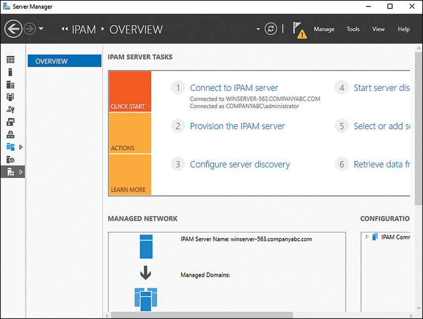
6. Click Next on the Before You Begin page.
7. On the Configure database page, choose a database in which to store the IPAM data, WID, or SQL Server 2008 R2 and later. This is a new feature of Windows Server 2016, as shown in Figure 10.29. You can choose the default Windows Internal Database (WID) for now. You can always return later and move the data to SQL Server.

8. On the Select Provisioning Method page, select Manual if you want to configure each server manually, or select Group Policy Based to allow the IPAM server to add (or remove) managed servers to (or from) the corresponding GPO. For this example, we select the Group Policy–Based radio button and then type in IPAM in the GPO Name prefix field, as shown in Figure 10.30. Click Next to continue.
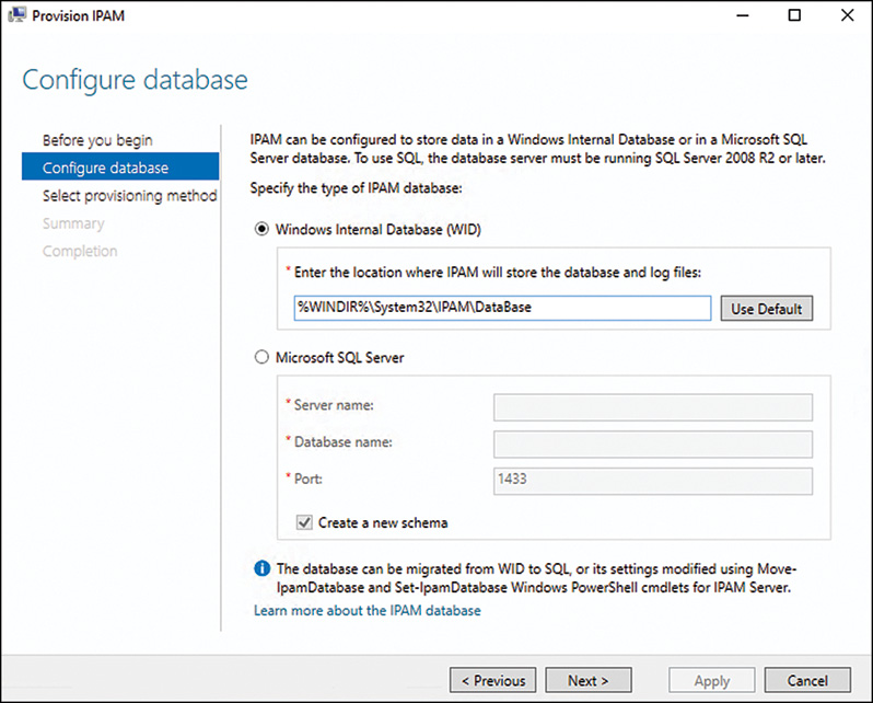
NOTE
When the IPAM Group Policy–Based Provisioning is selected, the group policies still need to be created using a separate process. Be sure to perform that process before servers are added to the IPAM console.
9. On the Summary page, review the details and note that with the IPAM GPO prefix that was entered in the previous section, three GPOs will be referenced by this IPAM server: IPAM_DNS, IPAM_DHCP, and IPAM_DC_NPS. Click Apply to complete the provisioning process on the IPAM server.
10. When provisioning completes, click Close to return to the IPAM console and close the Server Manager window.
This completes the IPAM provisioning process, and no other steps should be performed in the console until the next section is completed.
Configuring Servers for IPAM Management
You can configure IPAM-managed servers manually or through group policies. When done manually, each server type needs specific configurations, and although certain configurations may overlap between a DHCP and DNS server, for example, if you try to put all the configurations on each server you will run into some challenges and might open unnecessary security holes. To perform manual configuration of IPAM-managed servers, follow the steps on the specific server type as detailed in the following sections for DHCP, DNS, DC, and NPS.
When manual configuration is performed, a universal security group can be created in the domain named IPAMUG, and the IPAM server computer account should be made a member of this group. The following manual steps assume this task has been performed earlier. If this group is not desired, substitute the domainIPAMUG security group reference with the actual IPAM server computer account in the manual server configuration sections that follow.
Manually Configuring DHCP Servers
On all DHCP servers that will be IPAM-managed servers, follow these steps:
1. Add the domainIPAMUG security group to the local DHCP Users security group.
2. Add the domainIPAMUG security group to the local Event Log Readers security group.
3. Share the DHCP audit file path as dhcpaudit and configure the share and NTFS permissions to contain the domainIPAMUG security group with read permissions, as shown in Figure 10.31. The default path is C:WindowsSystem32DHCP, but this path can be discovered by opening the DHCP Manager console on the DHCP server, right-clicking the IPv4 node, and displaying the Advanced tab. This is also the default path used for IPv6 DHCP auditing.
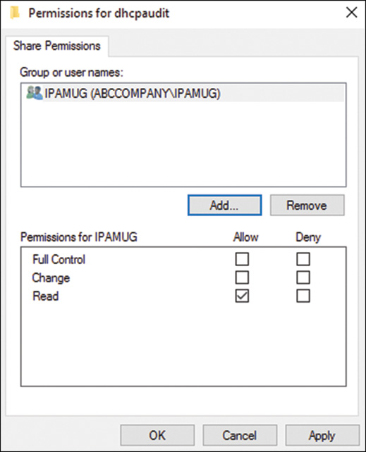
4. Enable the DHCP Server (RPC-In) Inbound Firewall rule.
5. Enable the DHCP Server (RPCSS-In) Inbound Firewall rule.
6. Enable the Remote Service Management (RPC) Inbound Firewall rule.
7. Enable the Remote Service Management (RPC-EPMAP) Inbound Firewall rule.
8. Enable the Remote Event Log Management (RPC) Inbound Firewall rule.
9. Enable the Remote Event Log Management (RPC-EPMAP) Inbound Firewall rule.
10. Enable the File and Printer Sharing (NM-Session-In) Inbound Firewall rule.
11. Enable the File and Printer Sharing (SMB-In) Inbound Firewall rule.
All of these firewall rules are pre-created Windows firewall inbound rules, and no special configuration should be required other than right-clicking the rule and selecting Enable Rule. Some of these rules may already be enabled, and those should be left as is.
Manually Configuring DNS Servers
On all DNS servers that will be IPAM-managed servers, follow these steps:
1. Add the domainIPAMUG security group to the local Event Log Readers security group for member server DNS servers or the Built-in local security group in the domain on a DNS server running on a domain controller.
2. For a member server DNS server, add the domainIPAMUG security group to the local Administrators group. For a domain controller DNS server, add the domainIPAMUG security group with read permissions to the DNS Server Security ACL using the DNS Manager console. Open DNS Manager on the desired DNS server and connect to the server. Right-click the server object and select Properties, and then open the Security tab. Add the domainIPAMUG group here with read permissions.
3. Enable the Remote Service Management (RPC) Inbound Firewall rule.
4. Enable the Remote Service Management (RPC-EPMAP) Inbound Firewall rule.
5. Enable the Remote Event Log Management (RPC) Inbound Firewall rule.
6. Enable the Remote Event Log Management (RPC-EPMAP) Inbound Firewall rule.
There are also four predefined DNS service group rules that need to be enabled, but these are already enabled when the DNS server role is installed, and no further action is required for IPAM communication.
Manually Configuring Domain Controllers and Network Policy Servers
On all domain controllers and NPS servers that will be IPAM-managed servers, follow these steps:
1. Add the domainIPAMUG security group to the local Event Log Readers security group for member server NPS servers or the Built-in local security group in the domain for domain controllers.
2. Modify the local security policy on NPS servers and the default domain controller policy for domain controllers with the following setting: Computer Configuration PoliciesWindows SettingsSecurity SettingsLocal PoliciesAudit PolicyAudit Account Logon Events (Success/Failure). By default, the Windows Security event log, which will capture these events, is set to overwrite as needed when the log reaches 131MB, so adjust this as required to ensure that IPAM can capture the necessary data before the log rolls over.
3. Enable the Remote Event Log Management (RPC) Inbound Firewall rule.
4. Enable the Remote Event Log Management (RPC-EPMAP) Inbound Firewall rule.
If this seems like maybe just a few too many steps to manage when configuring a server as an IPAM-managed server, you can automate this by creating the appropriate group policies. In our example, we selected Group Policy–Based configuration when we ran the IPAM Provisioning Wizard, and the following section details the steps that must be performed after provisioning is run but before servers are added to the IPAM console for management.
Creating Group Policy for IPAM Managed Server Configuration
When an IPAM server is provisioned and Group Policy–Based provisioning is selected, the group policies still need to be created in the necessary domains. These group policies include the necessary settings to modify security group membership, enable firewall rules, and other tasks to make IPAM communication work correctly. For this example, the domain name is companyabc.com, and the IPAM GPO prefix is IPAM. To create the GPOs, follow these steps:
1. Log on to the IPAM server using an account with domain administrator rights.
2. Open Windows PowerShell from the taskbar.
3. Type in the command Invoke-IpamGpoProvisioning -domain companyabc.com -gpoprefixname IPAM and press Enter. If there are multiple domains in the forest, this task should be performed once per domain.
4. Review the information displayed in the window, press the Y key, and then press Enter to confirm the changes and continue.
When this process completes, three new GPOs will be created in the domain, as shown in Figure 10.32.

Explore each of the three GPOs and notice that they are automatically linked at the domain level but that the Security Filtering section is empty, meaning that in the current state the policy will not be applied by any user or computer. Also during this step, the domainIPAMUG universal security group is added to the domain in the Users container with the IPAM server as the only member.
Configuring Server Discovery
When an IPAM server is provisioned, several tasks are created within the server’s task schedule, including one named the ServerDiscovery task. The ServerDiscovery task searches Active Directory to discover the DHCP, DNS, DC, and NPS servers registered with Active Directory and automatically adds them to the IPAM console. But before discovery can work properly, the domains that the IPAM server will search must be specified. To configure discovery, follow these steps:
1. Log on to the IPAM server or a server with the IPAM client tools installed and the IPAM server added to the server pool in Server Manager.
2. Click the Server Manager tile on the taskbar.
3. Click the IPAM link in the tree pane to display the IPAM console.
4. The IPAM console shows a list of six tasks, and the third one is Configure Server Discovery. Click this task, and when the window opens, select the desired domain from the pull-down list and click Add.
5. Check the type of servers that you want to discover in the domain and click OK, as shown in Figure 10.33.

6. After the necessary domains are added to the discovery scope, we can start the discovery process. In the IPAM console, click Start Server Discovery. The discovery task runs for several minutes or longer depending on the number of servers in the domain.
This completes the discovery process.
Defining Discovered Servers as IPAM Managed
After the discovery process has completed, all the discovered servers are listed in the IPAM console. The discovered servers are not yet ready to be managed by the IPAM server; they must first be defined as managed servers. To see the list of discovered servers and configure them as managed servers, follow these steps:
1. Log on to the IPAM server or a server with the IPAM client tools installed and the IPAM server added to the server pool in Server Manager.
2. Click the Server Manager tile on the taskbar.
3. Click the IPAM link in the tree pane to display the IPAM console.
4. The IPAM console shows a list of six tasks, and is the fifth is Select or Add Servers to Manage and Verify IPAM Access. Click this task, and when the window opens, all the discovered servers should be listed.
5. Discovered servers have a manageability status set to Unspecified. Right-click a discovered server and select Edit Server, as shown in Figure 10.34.

6. When the Add or Edit Server window opens, pull down the Manageability Status menu and select Managed, and then click OK to close the window.
7. Repeat this process on all the discovered servers, and they should then reflect a Managed state, but the Recommended Action column will show as Unblock IPAM Access. This is because the necessary firewall rules and security group membership changes have not yet occurred.
8. Open the Group Policy Management Console from the IPAM server or a domain controller and review the security filtering ACL of the IPAM GPOs. They should now include the discovered servers that were just configured as managed. If this is not the case, the problem might be that the user logged on to the IPAM console does not have the rights to edit these GPOs and that should be updated on the GPOs themselves.
9. After the discovered servers are set to Managed and appear in the GPO security filtering, to speed up IPAM management, you can reboot these servers to force group policy application and to run startup scripts that will need to be processed.
10. After the servers are rebooted and have run for at least one hour, return to the IPAM console, right-click each server, and select Refresh Server Access Status. When all servers show up in the Recommended Action column as IPAM Access Unblocked with a green check mark, you are ready to proceed with the collection of server data.
Defining IP Address Blocks
The IPAM console contains several nodes that include different sets of information. The core of all this is the IP Address Space node, which contains the IP Address Blocks, IP Address Inventory, and IP Address Range groups nodes beneath it. Before server data collection is forced or run, network administrators may want to define IP address blocks to ensure address data gets sorted appropriately. An IP address block is the highest-level address space defined in the IPAM console. The IP block should be created based on the actual IPv4 subnets and IPv6 network prefixes. DHCP IP Ranges and discovered and manually entered or imported IP addresses are sorted beneath the appropriate IP address blocks. For our network examples, we have an IPv4 IP address block of 192.168.206.x/24 and an IPv6 prefix of 2001:dba:ce::/64. To create an IP address block, follow these steps:
1. Log on to the IPAM server or a server with the IPAM client tools installed and the IPAM server added to the server pool in Server Manager.
2. Click the Server Manager tile on the taskbar.
3. Click the IPAM link in the tree pane to display the IPAM console.
4. In the tree pane of the IPAM console, click IP Address Space. In the center pane, you can review the terms and definitions of IP address blocks, IP address ranges, and IP addresses as desired.
5. In the IPAM tree pane, click the IP Address Blocks node beneath the IP Address Space node.
6. In the center pane near the top-right corner, click the Tasks link and select Add IP Address Block.
7. When the Add or Edit IPv4 Address Block window opens, type in 192.168.206.0 and click the Prefix pull-down menu to select the appropriate subnet mask of 24. Add a description and click OK, as shown in Figure 10.35.
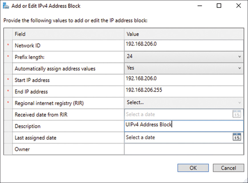
8. After returning to the IP address block, pull down the current view option and select IP Address Blocks to view the block just created.
9. In the IPAM console tree pane, near the bottom left, select IPv6, and in the center pane near the top-right corner, click the Tasks link and select Add IP Address Block once again.
10. Type in the IPv6 network ID of 2001:dba:ce:: and specify the prefix length of 64. Add a description and click OK, as shown in Figure 10.36.

This completes the creation of the IP address blocks.
Collecting Server Data
Server data collection will occur on a scheduled basis, as will event log collection. This is controlled by the default schedule set on the seven tasks, which can be view using the Task Scheduler console, as shown in Figure 10.37.

When data collection needs to be forced, you can do so as follows:
1. Log on to the IPAM server or a server with the IPAM client tools installed and the IPAM server added to the server pool in Server Manager.
2. Click the Server Manager tile on the taskbar.
3. Click the IPAM link in the tree pane to display the IPAM console.
4. The IPAM console shows a list of six tasks, and the sixth one is Retrieve Data from Managed Servers. Click this task and all the tasks will be started.
5. When the tasks complete, you can drill down in the tree pane under the IP Address Space node and the Monitor and Manage node to view the status of the servers and the IP address data.
Exploring the IPAM Console
The IPAM console has a lot of areas that contain different information. You might find it overwhelming at first, but after browsing through it and using it regularly, administrators should become comfortable retrieving information from this console and launching the management of DHCP and DNS services from it.
Overview Node
The Overview node of the IPAM console is always the place to start. From this node, you can jump right into tasks such as running discovery, collecting servers, or viewing the status of a managed server just by clicking on one of the numbers 1 through 6.
Server Inventory Node
The Server Inventory node is just as the name implies. This node shows the status of each of the discovered or manually added servers known by the IPAM server. In this node, when a server is selected, below it there will be a summary of the server IP information and IPAM configuration status. By right-clicking a single server or multiple servers, administrators can forcibly refresh IPAM server access data or kick off a server data collection cycle. Tasks available from this node enable an administrator to manually add servers that may have not been discovered by IPAM, such as a firewall, router, switch, or just a server that is not managed within Active Directory. Adding a server to the console does not mean that IPAM can manage it, but as a true IPAM solution, adding servers and IP information manually will be required in most enterprise and even smaller network. Remember that the goal is to be able to account for all IP addresses and managed devices.
IP Address Space Node
The Address Space node is where all the IP address information is stored. From here, administrators can view IP information for the enterprise and add or import data. When you select the IP Address Space node, only an informative page opens. Just select a subnode to view data or perform IP-related tasks.
IP Address Block Node
The IP Address Block node stores and details the state of the hierarchy of IP networks. When this node is selected, it displays only the IPv4 or the IPv6 information. This can be changed by selecting IPv4 or IPv6 in the bottom left of the IPAM tree pane. From this node, all IP-related tasks can be performed, such as adding IP address blocks, adding IP ranges, and importing data from external sources.
IP Address Inventory Node
Individual IP addresses can be tracked, and information will display within this node.
IP Address Ranges Node
The IP Address Ranges node displays all defined, imported, and discovered IP ranges. These include DHCP scopes and static IP ranges as defined by administrators, as shown in Figure 10.38.
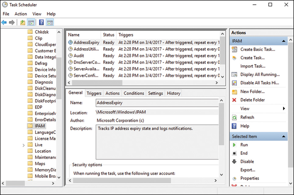
Monitor and Manage Node
The Monitor and Manage node displays the status of the managed servers and the status of their services.
DNS and DHCP Servers
This node includes all the DNS and DHCP servers that are managed by the IPAM server. When a server is selected in this node, more information will be displayed below. If desired, this is where the actual services on that managed system can be configured, as shown in Figure 10.38.
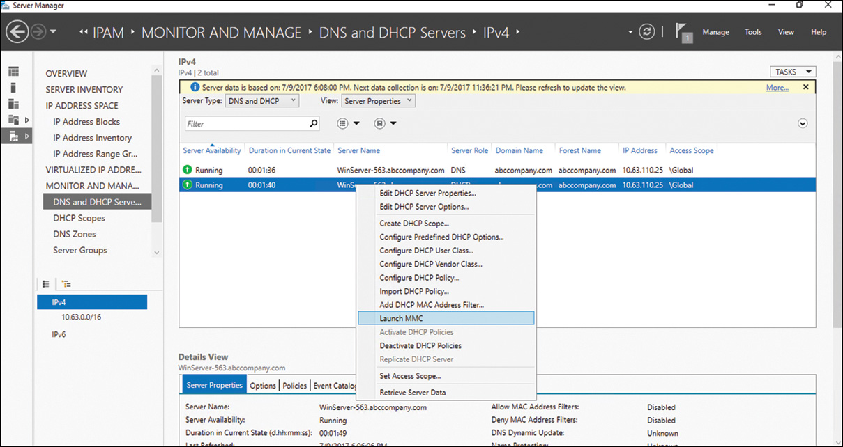
DHCP Scopes Node
In the DHCP Scopes node detailed information about DHCP scopes on managed servers will be presented. Right-clicking on a specific scope will present the administrator with options specific for managing the desired scope.
DNS Zone Monitoring Node
DNS servers’ zone files can be monitored from this node, and the status of the DNS zone will be displayed.
Event Catalog Node
The Event Catalog node is where in-depth analysis of managed server and services can be viewed. Event log data is collected and presented in this view for quick and easy access. IP address tracking data and DHCP and IPAM configuration changes can be viewed and searched from within this node.
Summary
This chapter details the DHCP service and IPv6 and the new IPAM server feature. With the growth and adoption of IPv6 expanding every day, administrators who do not learn the technology now are already behind the time. The new features of DHCP (including IPv6 scopes) can help administrators catch up to support IPv6 on their network sooner rather than later. With the addition of IPAM server on the network as well, network administrators have a powerful set of tools and functionality to take their network management to the next level. This gives network administrators the information they need to support and properly manage their network.
Best Practices
The following are best practices from this chapter:
![]() Perform all tests with DHCP split scope, failover scope, and security configurations in an isolated lab environment before deploying on a production network.
Perform all tests with DHCP split scope, failover scope, and security configurations in an isolated lab environment before deploying on a production network.
![]() When migrating DHCP services to a Windows Server 2016 system using the Windows Server migration tools, only install the DHCP service on the destination server but do not configure it (to avoid losing configuration settings or issues with DHCP authorization that might be presented after the import overwrites all the existing configurations).
When migrating DHCP services to a Windows Server 2016 system using the Windows Server migration tools, only install the DHCP service on the destination server but do not configure it (to avoid losing configuration settings or issues with DHCP authorization that might be presented after the import overwrites all the existing configurations).
![]() To avoid issues with the DHCP service account used for dynamic DNS registration, configure the account with a password that never expires, but change the password as frequently as the standard user password policy of the organization defines on the user account and in the DHCP configuration of each server using that account.
To avoid issues with the DHCP service account used for dynamic DNS registration, configure the account with a password that never expires, but change the password as frequently as the standard user password policy of the organization defines on the user account and in the DHCP configuration of each server using that account.
![]() Deploy DHCP services with some level of redundancy on all deployments, leveraging split scopes, failover scopes, and clusters.
Deploy DHCP services with some level of redundancy on all deployments, leveraging split scopes, failover scopes, and clusters.
![]() When designing IPv6 networks for internal usage, always use ULA range to conform to RFC 4193.
When designing IPv6 networks for internal usage, always use ULA range to conform to RFC 4193.
![]() When notating IPv6 addresses, use notation standards to reduce the total number of characters required to properly represent the IPv6 address or network prefix.
When notating IPv6 addresses, use notation standards to reduce the total number of characters required to properly represent the IPv6 address or network prefix.
![]() When deploying IPAM server, use group policy provisioning to simplify managed server configuration, and deploy the GPOs before configuring servers as managed.
When deploying IPAM server, use group policy provisioning to simplify managed server configuration, and deploy the GPOs before configuring servers as managed.