
This short example explores the conceptual modeling functionality in Revit Architecture for creating massing models very rapidly for architectural form-finding. The chosen example is a high-rise office building. This project is intended to be conducted as an instructor-led workshop therefore, only tasks are listed in each section and not the step-by-step instructions to complete the task. Information on tasks can be found in the on-screen help (F1).
To complete the office building in this exercise, follow the steps outlined here.
1
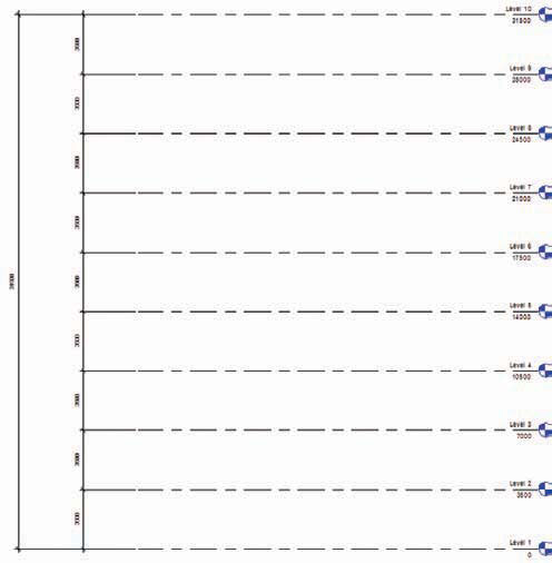
Levels:
Open File: DefaultMetric.rte or (step01.rvt).
Create a new project using the New Project button.
Save File: Conceptual Model.rvt.
Define levels in any elevation view: floor to floor heights will be 138 in (3,500 mm). Change Level 2 elevation to 138 in (3,500 mm). Create levels 3 to 10 with the same 138 in (3,500 mm) distance.
Create plan views of new levels: select the View Design bar then select the Floor Plan command and select all levels. Accept default settings.
There is always more than one way to get a good result; try this one: Create new eight times and use the dimension and the EQ to set up the distance of 138 in (3,500 mm).
Save file.
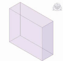
Rectangular form:
Open File: Conceptual Model.rvt or (step02.rvt). Model rectangular form in floor plan view—Level 1. Massing Design Bar.
Create Mass command.
Accept default name.
Solid Form > Solid Extrusion.
Rectangular Form Dimensions: 1418 in (36,000 mm) x 473 in (12,000 mm) x 10 stories.
Place rectangle in upper half of project file within the elevation markers.
Save file.
3
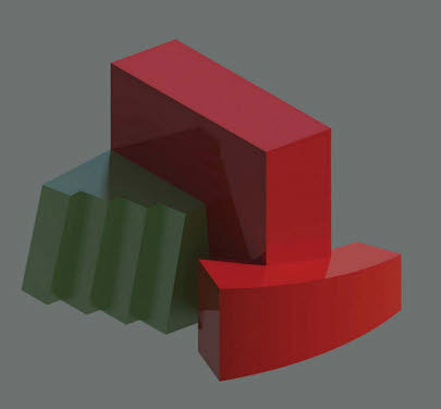
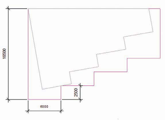
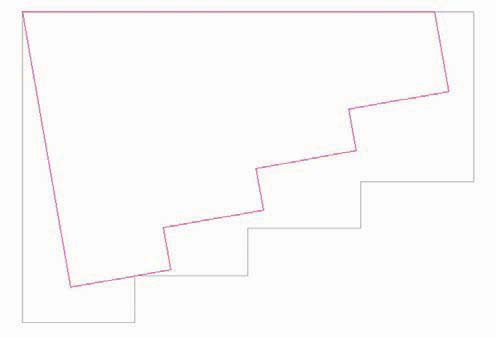
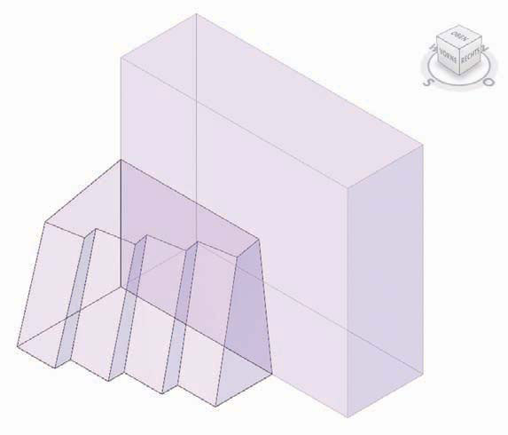
Sawtooth form:
Open File: Conceptual Model.rvt or (step03.rvt). Model sawtooth form in plan view—Level 1. Massing Design Bar.
Create Mass command.
Solid Form > Solid Blend.
Begin the sketch from lower left corner of rectangle.
Draw Down 650 in (16,500 mm), Right 236 in (6,000 mm), Up 98 in (2,500 mm).
Copy the last two segments three times to create the sawtooth form and drag the last vertical segment to bottom edge of the rectangle.
Close the form with another sketch.
Select the bottom lines.
Resize the sketch lines by 0.9 (numerically); use the upper left corner of sketch as the base point.
Remove the top horizontal sketch line from the selection set.
Rotate the remaining sketch lines 10 degrees counter-clockwise, using the upper left corner as the pivot point.
Close the form with another sketch.
Set Height of sawtooth form.
South Elevation View.
Select sawtooth form and drag top handle to Level 6.
Save file.
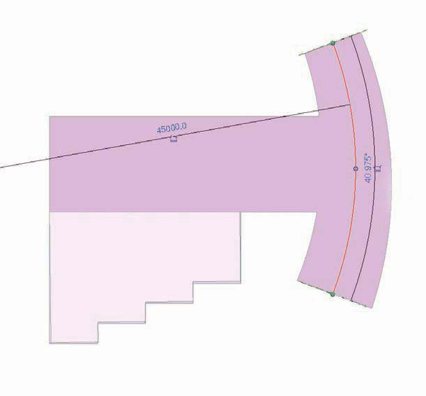
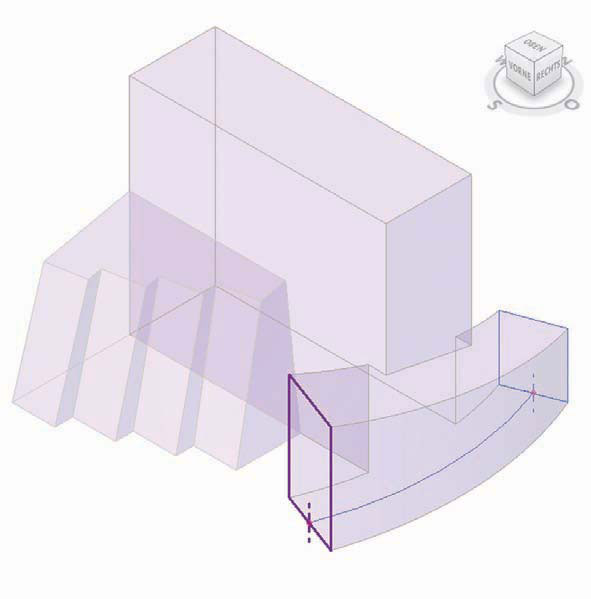
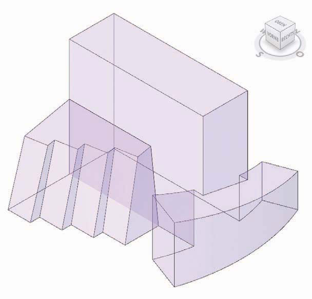
Swept blend:
Open File: Conceptual Model.rvt or (step04.rvt). Edit existing rectangular form.
Floor Plan—Level 1.
Select rectangular form.
Edit button above drawing window.
Add swept blend form.
Add to existing Mass Group.
Select the rectangular form for editing.
Solid Form > Create Path. Pick arc passing through three points mode, path start point above model, path end point below model; Set Radius = 1,772 in (45,000 mm) (type in).
Create Profile 1: sketch a rectangle (300 in wide by 355 in/7,600 mm wide by 9,000 mm) and center bottom of sketch on path.
Create Profile 2: sketch a rectangle (394 in wide by 591 in/10,000 mm wide by 15,000 mm) and center bottom of sketch on path.
Join Geometry (rectangular and swept blend).
While still in the Mass Group, Edit mode (so don’t finish now).
Use the Join Geometry tool to combine the rectangular and swept blend forms together.
Select the rectangular form first; select the swept blend form.
Exit the Mass Group, Edit mode.
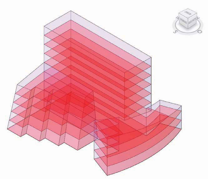
5
Apply mass floors:
Open File: Conceptual Model.rvt or (step05.rvt). Create floors.
Select massing form.
Click Massing Floor button above drawing window. Select floors 1 to 10.
Add a check to the selection set.
Repeat as necessary for each massing form.
Save file.
6
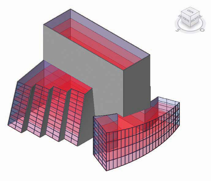
Apply walls to masses:
Open File: Conceptual Model.rvt or (step06.rvt). Create wall by face.
Basic wall—generic—8 in (200 mm).
Set Location Line to finish face interior.
Create Curtain System by face.
Curtain System 59 x 118 in (1,500 x 3,000 mm).
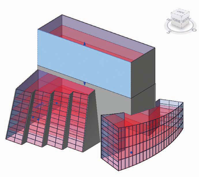
Split Walls:
Select the Split tool.
Place the cursor on the vertical edge of the south wall of the rectangular form.
Left-click just above the sawtooth form.
Repeat the procedure for the east wall.
Note: You may receive warnings during the Split procedure. Dismiss warnings.
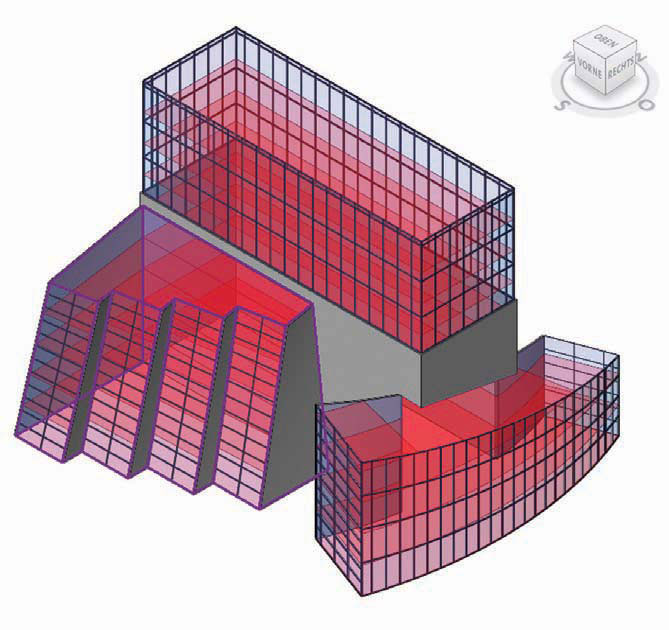
Substitute wall types:
Change highlighted walls in red, to:
Curtain Wall—Exterior Glazing.
Note: You may receive warnings during the Split procedure. Dismiss warnings.
Apply 3D Mullions from the Modeling Design bar.
Select Mullion and use the default 2 x 6 in (50 x 150 mm) rectangular profile.
Apply to each curtain-wall surface.
Save file.
8
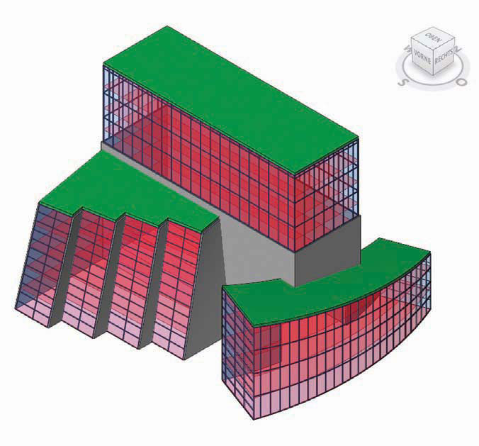
Apply roofs to masses:
Open File: Conceptual Model.rvt or (step07.rvt).
Create roof by face.
Sawtooth roof.
Select top of form.
Rectangular and swept blend.
Select tops of forms.
Save file.

9
Apply floors to masses:
Open File: Conceptual Model.rvt or (step08.rvt).
Create floor by face.
Select concrete—domestic 163⁄4 in (425 mm).
Create a crossing-window selection set of the entire massing model.
Click Create Floors button above drawing window.
10
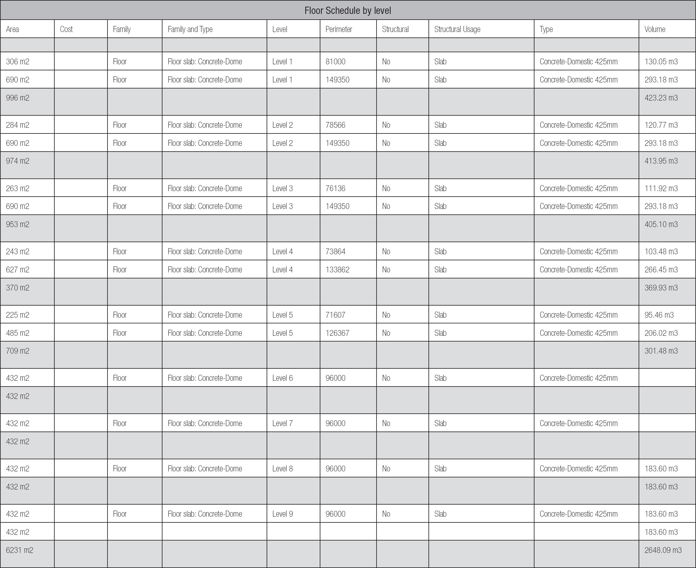
Schedules:
Open File: Conceptual Model.rvt or (step09.rvt).
Create a schedule.
Wall by type.
Floors by level.
Mullion by length.
Save file.
11
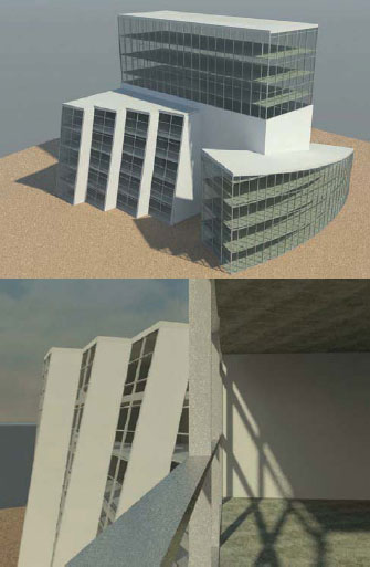
Render model:
Open File: Conceptual Model.rvt or (step10.rvt).
View Control toolbar.
Enable Shadows ON.
Render Design bar.
Select Render dialogue.
Lighting to exterior—sun only.
Set quality level to Draft (1 minute); Medium (10 minutes).
Click Render button to begin the rendering process.
Bonus:
Add site topography object from Site Design bar.
Try new materials.
Save file.