
STEP BY STEP POLYGON MODEL EDITING
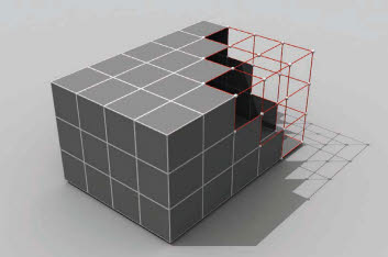
A Polygon mesh can be edited on a sub-object level (referred to as “sub-object editing”). The key principle behind this form of mesh manipulation is that the modeler has access to the basic structural components that form a mesh. These components consist of vertices, edges, and polygons that can be manipulated to alter the form of the mesh.

1
Vertices. A vertex is the most basic element of a mesh. Vertices are single structural points that define the corners of each face within the mesh.
2
Edges. Edges are the second most basic element of a mesh. Edges tie the vertices together to form the edges of faces within the mesh.

Polygons. Polygons are formed by connecting vertices and edges together. Polygons are a series of faces that are connected to form a mesh.

4
Select vertices. Adjusting its vertices can modify a mesh. The desired vertices must first be selected.

5
Edit vertices. The selected vertices can be manipulated using the Move, Rotate, and Scale tools. Additional editing tools are available within the Modify tab for manipulating the mesh’s vertices.

Select edges. Adjusting its edges can modify a mesh. The desired edges must first be selected.

7
Edit edges. The selected edges can be manipulated using the Move, Rotate, and Scale tools. Additional editing tools are available within the Modify tab for manipulating the mesh’s edges. In this case a Chamfer tool was used to chamfer the selected edges.
8
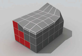
Select faces. Adjusting its polygons can modify a mesh. The desired polygons must first be selected.

Edit faces. The selected polygons can be manipulated using the Move, Rotate, and Scale tools. Additional editing tools are available within the Modify tab for manipulating the mesh’s polygons. In this case the polygons were extruded using the Extrude tool.
10
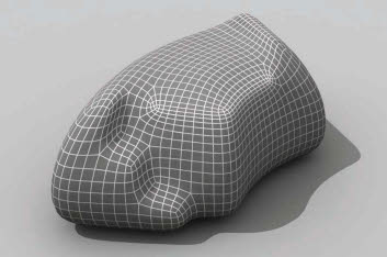
Using modifiers. Modifiers can be applied to the mesh to further alter its form. In this case the Turbo Smooth, Bend, and Taper modifiers were used to further manipulate the mesh’s form.

11
Mapping coordinates. A material was assigned to the surface. The UVW Map modifier was used to map the material correctly onto the surface.