
Axonometric and isometric projections
Axonometric projection is one of the most frequently used drawing types for creating three-dimensional images in architecture. Isometric, dimetric, and trimetric projections are types of axonometric drawings and together they form a group of drawing types called parallel projections or paraline drawings. These are three-dimensional drawings, projected using orthographic projections as generators, where all parallel lines in the object remain parallel in the drawing. Objects drawn in parallel projections do not appear to get smaller or larger as they recede, and line lengths remain dimensionally accurate.
Isometric drawings are formed when an object is turned so that all three axes meet the picture plane at the same angle, making the angles between the edges of the building or space 120 degrees. An isometric drawing can be drawn at any scale and so best illustrates the true projected size. In architectural drawings one axis is usually vertical and the other two are therefore at 30 degrees to the horizontal. Most architectural drawings are shown from the point of view of looking down (though details and ceilings may be best seen looking up) and view a plan that appears to be “opened up” in the direction of viewing from 90 to 120 degrees. This is advantageous if the drawing reveals an interior, but otherwise is a relatively rigid projection that requires all three visible planes to be emphasized equally.
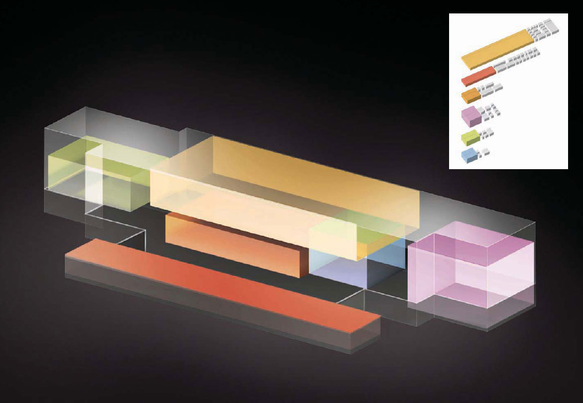
These diagrams were created for the Center for Music, Art, and Design at the University of Manitoba, Winnipeg, by Patkau Architects. Both were modeled in AutoCAD, rendered in VIZ, and enhanced in Photoshop. The six large, flexible primary spaces are shown colored, and the support spaces are gray. To describe the disposition of the primary spaces within the overall building, the building was represented as a transparent cubic form with the colored primary spaces inside it.
Axonometric is the term used in architecture to describe a projection from a plan to scale. Like isometric, axonometric drawing is a form of parallel projection: plan elements are projected vertically and to the same scale as the plan, which is first rotated to provide the intended view. Walls that appear at the front of the plan can be omitted or only partially projected to create a “cutaway” axonometric which reveals the interior that would otherwise be obscured by uniform projection. The cutaway drawing is a useful tool for describing spatial sequences or narratives that link different levels in a building.
Dimetric projection is rarely used today because it is not a standard projection. For Modernists, on the other hand, the dimetric projection was a common drawing type due to the flexibility of viewing angles it allows. In dimetric projection the image can be adjusted in terms of the scale of axis, and also in terms of two viewing angles, allowing asymmetric adjustment to correct the visual distortion that inevitably accompanies a more rigid projection type. Two of the three angles are equal with the picture plane and the third angle is different, so that two of the three axes appear equally foreshortened and the scale of the third direction (vertical) is determined separately. Although there is a degree of complexity to drawing dimetric projections, since they require the use of a scale factor and an adjustment of two angles to the picture plane, there is also flexibility otherwise not accommodated in projections of this kind. This drawing type allows an infinite variety of viewing angles relatively simply and so is also popular in computer games.
The least common, but most flexible, of these drawing types is trimetric projection, where all three axes appear unequally foreshortened and the scale of each foreshortened side is determined by the angle of viewing. This added foreshortening gives these drawings an unnecessary degree of complexity for most architectural ideas, which can usually be represented through one of the other axonometric drawing types.

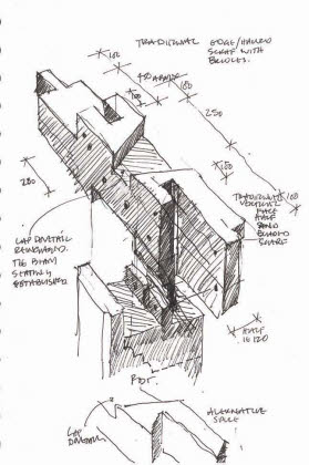
Garry Butler (of Butler & Hegarty Architects) has developed a deep understanding of timber joinery through detailed surveys and careful restoration. These on-site axonometric sketches are brilliant examples of how this type of drawing (together with sketch plans and sections) is perhaps the only way to understand complex details of this kind.