
STEP BY STEP CREATING A SPLINE SURFACE MODEL
1
Splines. Create required spline shapes using the Line tool. For multiple splines, attempt, where possible, to use an equal number of vertices on each spline. Create one spline object by attaching all the splines together. When attaching the splines, select the lowest spline and attach each spline in order of sequence.

2
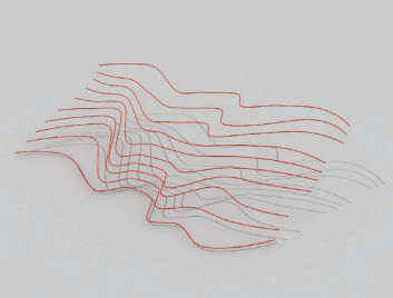
Spline cage. Create a spline cage by connecting the vertices with new splines to form a closed lattice made up of three- or four-sided shapes. The Cross-section modifier can be used, or connect the vertices manually using the Create Line tool from within the Edit Spline parameters.
When creating the splines manually, make sure the vertices align properly by using the 3D Snap function.
When using the Cross-section modifier, the first vertices of each spline should all start at the same side so that the modifier works correctly.

Surface. Use the Surface modifier to create surface mesh over the spline cage.

4
Surface final. Adjust the parameters for the surface modifier to suit. The spline cage must be made of a three- and/or four-sided grid to prevent any holes from appearing in the surface mesh. At the junction where two splines cross, the two respective vertices must align exactly so that the surface mesh is created properly.
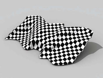
5
Mapping a material. A material was assigned to the surface. The UVW Map modifier was used to map the material correctly to the surface.