
A plan is a fundamental architectural drawing type. It is a primary organizing device. As a consequence it is the central drawing to a great many projects, and is the drawing through which buildings can most easily be read. At the same time, it is only one part, albeit a significant one, of a whole range of drawings that eventually describe a building in detail.
Technically a plan may be described as an orthographic projection from the position of a horizontal plane. The position of this plane and the scale of the drawing can produce a wide variety of plan types, ranging from landscapes to details. The scale of the plan drawing is important in determining not only the level of detail illustrated, but also the graphic style. For instance, a detail drawing whose purpose is solely to convey information may be appropriately carried out in line, while a plan of a city or landscape may be rendered to indicate topographic information or, in the case of a city, internal and external space. Together the scale and drawing technique of a plan will play an important role in determining what it communicates.
In most projects the plan may be described as something of a “hinge;” the element about which other drawings turn, and the element from which springs a range of spatial studies. If the plan does not work, both pragmatically and within the frame of the overall intention, then other drawings are inevitably compromised.
TIP CONVENTIONS FOR PLANS
• Show everything that is seen below the plan cut (typically taken at 3 ft (1 m) above floor level).
• Differentiate between elements that are cut in the plan with heavier line weights.
• Elements that are not cut, but which are visible, should have a lighter line weight.
• Significant elements that are above the plan cut (i.e. not visible) should be shown dotted.
• Voids to floors below the plan are indicated with crossed lines.
• Voids to floors above are shown with dotted crossed lines.
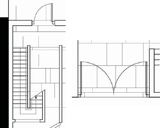
• Arrows on stairs indicate upward direction.
• Like walls, stairs are cut where the plan is taken.
• Show doors in open position.
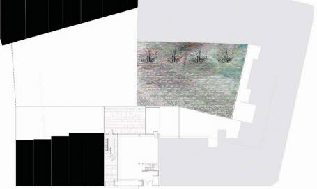
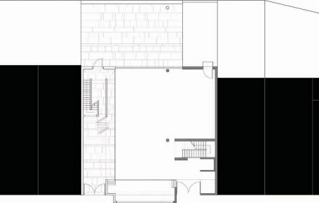
This site plan identifies the proposal by blocking out the context (on the left). Alternatively, one can choose to render just the external spaces (as on the right of the plan), but not both internal and external spaces.
For plans of buildings, the plane of the floor plan is taken a little above, and parallel to the level of, the floor it describes, so that the projected drawing looks straight down onto the floor plane. Of the conventions that govern building plans, the most important concern graphic style and line weights. The key purpose of a plan drawing, in particular, is to communicate information and the key elements of a plan are the vertical planes it cuts through. These can either be shown with a heavier line weight or by rendering the insides of cut walls. All other lines that are visible below the line of the plan are drawn in a lighter line, and significant parts of the building that appear above it (a staircase or ceiling plan, for example) are typically drawn as dotted lines.
In contrast to the conventions that have traditionally governed building plans, other kinds of plan drawings can be more exploratory and wide-ranging in their use of technique, evocative in the role they play in generating ideas for the three-dimensional development of the building as a whole. Other kinds of sketch plans are spontaneous and capture the essence of an arrangement. This kind of drawing is deceptive. Though it is quick in its execution, it requires a real understanding of dimension that comes from experience of observing, measuring, and drawing existing spaces and objects—measured drawings retain a real value.
TIP SCALE
Above all else a plan should convey information clearly. Always draw a plan to a specific scale (or at full scale in CAD). The conventional metric engineering scales are 1:10,000; 1:2,500; 1:1,250; 1:500; (landscapes/urban contexts) 1:200; 1:100. Conventional imperial architecture scales for overall buildings are 1⁄4”:1’0”; 3⁄4”:1’0”; for individual rooms/details 11⁄2”:1’0” and 3”:1’0” for details. See page 201 for a table of metric scales and their imperial equivalents.
Line weights differentiate elements in the plan, such as walls. These can either be shown as heavier lines (as used on the left side of the plan) or solid filled lines (as used on the right side of the plan).