
2
Light-Activated Night-Light
This project is a simple test of a photoresistor’s functionality: we’ll create a night light that gets brighter depending on the amount of light detected.
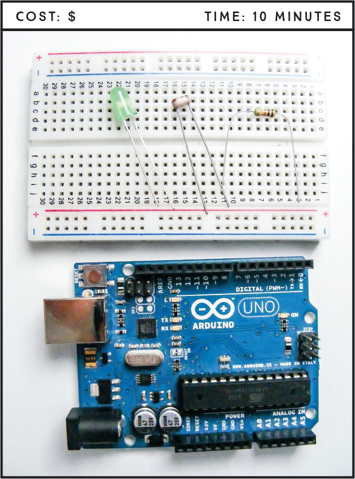
PARTS REQUIRED
Arduino board
Breadboard
Jumper wires
Photoresistor
LED
10k-ohm resistor
HOW IT WORKS
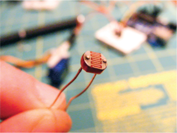
A photoresistor is a variable resistor that reacts to light; the less light that shines on it, the higher the resistance it provides. This resistance value varies the voltage that’s sent to the input pin of the Arduino, which in turn sends that voltage value to the output pin as the power level of the LED, so in low light the LED will be bright. There are different styles of photoresistors, but they usually have a small, clear, oval head with wavy lines (see Figure 2-1). Photoresistors do not have polarity, so it doesn’t matter which way you connect the legs.
The principles at work here are similar to those of a child’s night-light. You can use a photoresistor to control more than just LEDs, as we’ll see in upcoming chapters. Since we only have two power and GND connections, we won’t be using the breadboard power rails here.
THE BUILD
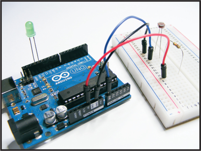
Place your photoresistor in the breadboard, connecting one leg to GND directly on the Arduino and the other leg to Arduino A0.
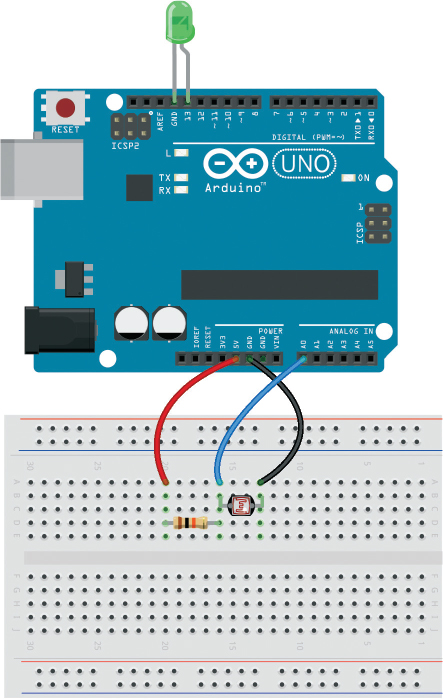
Connect one leg of the 10k-ohm resistor to +5V, and connect the other leg to the A0 photoresistor leg, as shown in the circuit diagram in Figure 2-2.
FIGURE 2-2: The circuit diagram for the light-activated LED
Insert the longer, positive leg of the LED directly into pin 13 on the Arduino and the shorter, negative leg directly into Arduino GND. We would normally use a resistor to limit the current to an LED, but we don’t need one here because pin 13 on the Arduino has one built in.
Upload the code in “The Sketch” below.
THE SKETCH
The sketch first connects the photoresistor to Arduino pin A0 as our INPUT and the LED to pin 13 as our OUTPUT. We run the serial communication with Serial.begin(9600), which (when your Arduino is connected to your PC) will send information to the Arduino’s Serial Monitor. This means the resistance value of the photoresistor will be displayed in the Serial Monitor on your computer, as shown in Figure 2-3.
FIGURE 2-3: The Serial Monitor will display the resistance of the photoresistor.
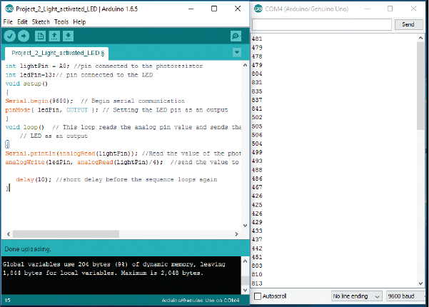
The loop reads the photoresistor’s analog value and sends it to the LED as a voltage value. The A0 pin can read 1,024 values, which means there are 1,024 possible brightness levels for the LED. Minuscule changes between this many levels aren’t very visible, so we divide that number by 4 to scale down to only 256 values, making it easier to detect when there is a change in voltage to the LED.
int lightPin = A0; // Pin connected to the photoresistor
int ledPin = 13; // Pin connected to the LED
void setup() {
Serial.begin(9600); // Begin serial communication
pinMode(ledPin, OUTPUT); // Setting the LED pin as an output
}
// This loop reads the analog pin value and
// sends that to the LED as an output
void loop() {
// Read the value of the photoresistor
Serial.println(analogRead(lightPin));
// Write the value to the Serial Monitor
// Send the value to the ledPin and divide by 4
analogWrite(ledPin, analogRead(lightPin) / 4);
delay(10); // Short delay before the sequence loops again
}
TROUBLESHOOTING
Q. The code compiles, but the LED does not light when it’s dark.
• Make sure that the LED is inserted with the long, positive leg in pin 13 and the short, negative leg in GND next to it.
• Make sure the photoresistor is connected to Arduino A0 as shown in the circuit diagram in Figure 2-2. Open the Serial Monitor to see if there’s a reading. If you’re getting a reading but the LED doesn’t light, the LED may be faulty, so try replacing it with another one.