22
Ultrasonic Robot
In this project we’ll combine an ultrasonic sensor with two DC motors and a servomotor to create a simple object-avoiding robot.
PARTS REQUIRED
Arduino board
Jumper wires
L293d motor shield
2 DC motors and wheels*
HC-SR04 ultrasonic sensor
9V AA battery pack
Robot base with fittings*
Center wheel*
Tower Pro SG90 9g servomotor
LIBRARIES REQUIRED
Servo
NewPing
Adafruit Motor Shield V1
* These items can be purchased as part of a kit
HOW IT WORKS
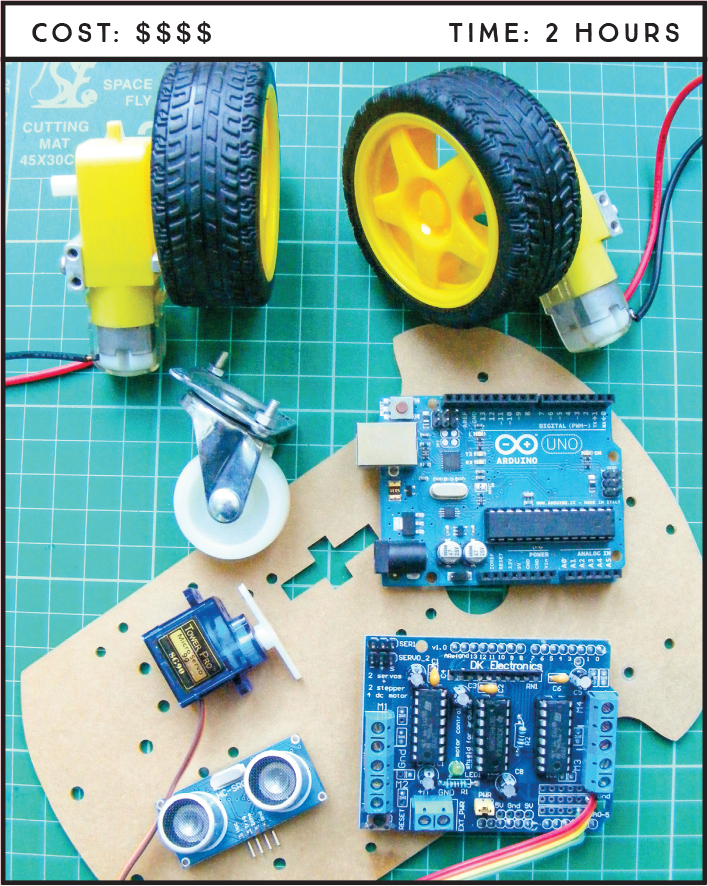
The key parts of the ultrasonic robot are the HC-SR04 ultrasonic sensor, L293d motor shield, and the motors. The motors I used were purchased as part of a kit; if you search online for “Arduino robot kit,” you too should be able to find a kit that contains the motors and wheels, base, battery pack, center wheel, and fittings needed. The one I bought is called the “2WD Smart Motor Robot Car Chassis Kit for Arduino 1:48,” so try a few of those keywords until you find something similar to the kit in Figure 22-1. Also try the suppliers listed in the “Retailer List” on page 249.
The ultrasonic sensor sends and receives a signal to determine the distance of an object. If there is an object less than 15 centimeters away, the robot will stop, look around, turn toward a direction in which it doesn’t sense anything, and move in that direction. The ultrasonic sensor is mounted on a servomotor so that the robot can move and search for a clear route. For more on how the HC-SR04 ultrasonic sensor works, see Project 13. The L293d motor shield fits on top of the Arduino and controls the DC motors using the Adafruit Motor Shield library.
THE BUILD
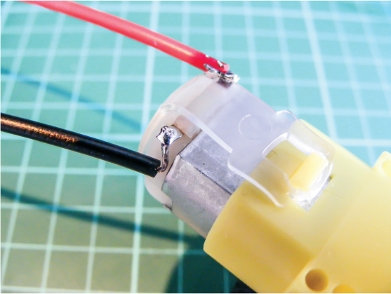
You will need to solder wires to the DC motors as shown in Figure 22-2. See the “Quick Soldering Guide” on page 12 if you need a refresher on how to do this. Solder the red, positive power wire to the left pin of one DC motor and the black ground wire to the right pin; reverse this order for the other motor. DC motors do not have polarity, so it doesn’t matter which way you hold the motors to determine which is left and right, but power and GND need to be in opposite positions on the motors so the direction of the revolution will be the same.
FIGURE 22-2: Solder the red, positive power wire to the left pin of one DC motor, and the black ground wire to the right pin. Reverse this order for the other motor.
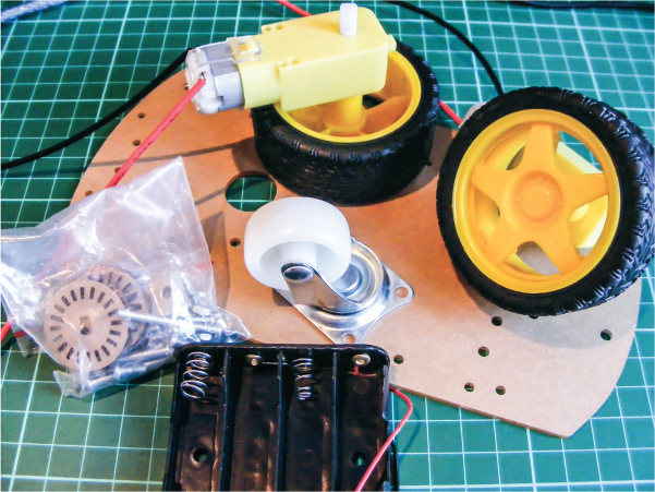
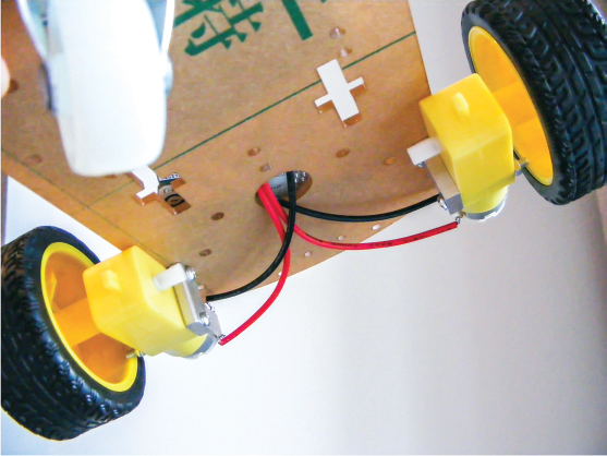
Attach the single wheel to the front of the robot base and the two rear wheels to the back using the screws and fittings provided. The underside of the robot should resemble Figure 22-3.
FIGURE 22-3: Assemble the base of the Arduino robot.
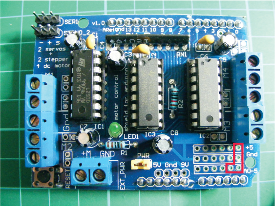
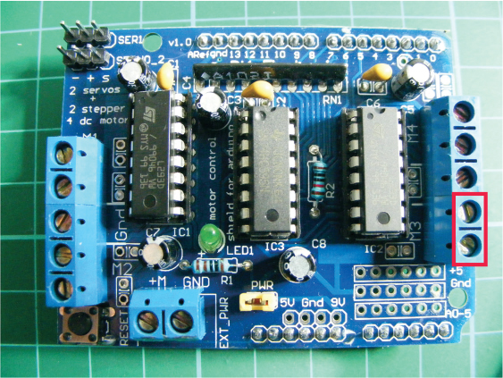
Now you need the L293d motor shield (Figure 22-4); we’ll solder some wires to it to control the ultrasonic sensor.
FIGURE 22-4: The L293d motor shield. We’ll solder four wires to the pins highlighted in the image.
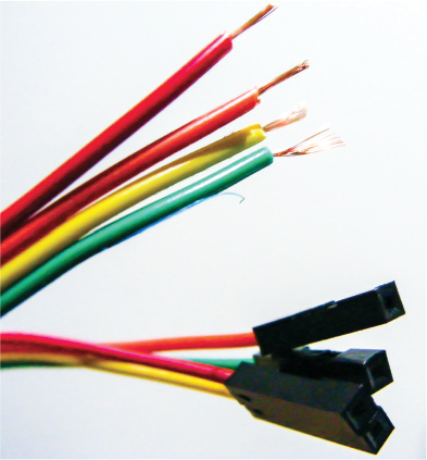
Take four female jumper wires and strip about 5 millimeters from one end of each, as shown in Figure 22-5.
FIGURE 22-5: Strip the ends of four female jumper wires to solder onto the motor shield.
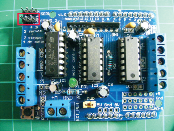
Solder the stripped ends to the highlighted pins on the motor shield, as shown in Figure 22-6. This can be tricky, so take your time to create the best connection you can.
FIGURE 22-6: Solder the jumper wires to the motor shield (shown in Figure 22-4). The two pins below the power connections should connect to analog A4 and A5 to control the sensor.
Once you’ve soldered the wires to the motor shield, place the shield on top of the Arduino so that the pins of the shield line up with the holders in the Arduino below. The shield should fit exactly, but take care to align the pins to the holes and gently lower it in place.
Next, connect the ultrasonic sensor to the female ends of the jumper wires you soldered to the motor shield. Connect VCC on the sensor to +5V on the motor shield, Trig to A4, Echo to A5, and GND to GND (see the following table).
ULTRASONIC SENSOR
MOTOR SHIELD
VCC
+5V
Trig
Pin A4
Echo
Pin A5
GND
GND
Connect the wires from the DC motors to the motor shield as shown in the following tables and Figure 22-7. You connect the wires by feeding them through the pin and using the screws to grip the wires in place.
LEFT MOTOR
MOTOR SHIELD
ARDUINO
Red wire
M1
+5V
Black wire
M1
GND
RIGHT MOTOR
MOTOR SHIELD
ARDUINO
Red wire
M3
+5V
Black wire
M3
GND
FIGURE 22-7: Connect the power wires of the DC motors as shown.
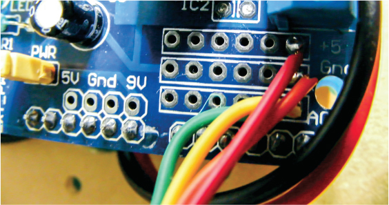
Next attach the servomotor to the shield, as shown in the following table and Figure 22-8.
SERVOMOTOR
MOTOR SHIELD
ARDUINO
Brown wire
Servo_2 -
GND
Red wire
Servo_2 +
+5V
Yellow wire
Servo_2 s
Signal
FIGURE 22-8: Connect the servomotor to the shield as shown.
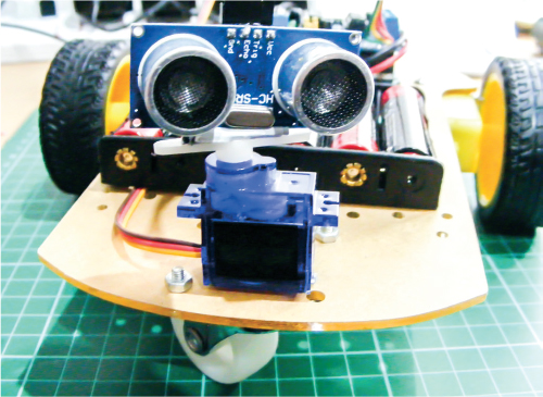
Attach the servomotor to the front of the robot using glue or tape. Then attach the ultrasonic sensor to the horn of the servomotor so it moves with the servo arm and your robot can look around. At this stage the robot should look something like Figure 22-9.
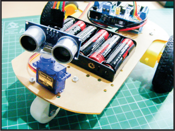
FIGURE 22-9: The completed robot with ultrasonic sensor attached to the servomotor
Make sure you’ve downloaded the NewPing and Adafruit Motor Shield libraries and added them to your IDE. The Servo library is already included in the IDE, so you don’t need to install it.
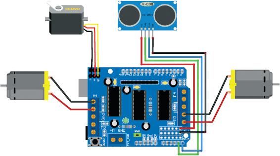
Once you’ve confirmed that your setup matches the circuit diagram in Figure 22-10, upload the code in “The Sketch” on page 198 and connect the 9V battery pack to your Arduino to see your robot in action!
FIGURE 22-10: The circuit diagram for the ultrasonic robot
THE SKETCH
The sketch starts by calling on the Adafruit Motor Shield, NewPing, and Servo libraries. The Trig pin of the ultrasonic sensor is defined as Arduino A4 and the Echo pin as Arduino A5. The maximum distance of the ultrasonic sensor is set at 200 centimeters and the speed of the DC motors is set at a medium speed of 190 (out of 255). The DC motors are defined to use connections M1 and M3 of the motor shield.
The servo is given a name and attached to pin 9 on the Arduino (via the connection on the motor shield). The loops after that take a reading from the ultrasonic sensor and, if it detects that an object is less than 15 centimeters away, the motors stop and reverse slightly, the servo moves left and right once to look around, and the robot turns to the left and continues to move forward until it discovers another object.
// Reproduced with kind permission from Nick Koumaris
// http://www.educ8s.tv
#include <AFMotor.h>
#include <NewPing.h>
#include <Servo.h>
#define TRIG_PIN A4
#define ECHO_PIN A5
#define MAX_DISTANCE 200
#define MAX_SPEED 190 // Sets speed of DC motors
#define MAX_SPEED_OFFSET 20
NewPing sonar(TRIG_PIN, ECHO_PIN, MAX_DISTANCE);
AF_DCMotor motor1(1, MOTOR12_1KHZ); // First motor to connection 1
AF_DCMotor motor2(3, MOTOR12_1KHZ); // Second motor to connection 3
Servo myservo; // Give the servo a name
boolean goesForward = false;
int distance = 100; // Define an int for distance and speed
int speedSet = 0;
void setup() {
myservo.attach(9); // Servo attached to pin 9
myservo.write(115); // Set servo at 115 degrees
delay(2000);
distance = readPing(); // Read the distance from the sensor
delay(100);
distance = readPing();
delay(100);
distance = readPing();
delay(100);
distance = readPing();
delay(100);
}
void loop() {
int distanceR = 0;
int distanceL = 0;
delay(40);
// If distance is less than 15 cm, carry out this function
if (distance <= 15) {
moveStop();
delay(100);
moveBackward();
delay(300);
moveStop();
delay(200);
distanceR = lookRight();
delay(200);
distanceL = lookLeft();
delay(200);
if (distanceR >= distanceL) {
turnRight();
moveStop();
} else { // Or else carry on
turnLeft();
moveStop();
}
} else {
moveForward();
}
distance = readPing();
}
int lookRight() { // The servo looks to the right
myservo.write(50);
delay(500);
int distance = readPing();
delay(100);
myservo.write(115);
return distance;
}
int lookLeft() { // The servo looks to the left
myservo.write(170);
delay(500);
int distance = readPing();
delay(100);
myservo.write(115);
return distance;
delay(100);
}
int readPing() {
delay(70);
int cm = sonar.ping_cm();
if (cm == 0) {
cm = 250;
}
return cm;
}
void moveStop() {
motor1.run(RELEASE);
motor2.run(RELEASE);
}
void moveForward() {
if (!goesForward) { // If area is clear, motors move forward
goesForward = true;
motor1.run(FORWARD);
motor2.run(FORWARD);
// Slowly bring up speed to avoid loading down
// batteries too quickly
for (speedSet = 0; speedSet < MAX_SPEED; speedSet += 2) {
motor1.setSpeed(speedSet);
motor2.setSpeed(speedSet + MAX_SPEED_OFFSET);
delay(5);
}
}
}
void moveBackward() {
goesForward = false;
motor1.run(BACKWARD);
motor2.run(BACKWARD);
// Slowly bring up speed to avoid loading down
// batteries too quickly
for (speedSet = 0; speedSet < MAX_SPEED; speedSet += 2) {
motor1.setSpeed(speedSet);
motor2.setSpeed(speedSet + MAX_SPEED_OFFSET);
delay(5);
}
}
void turnRight() { // Movement for turning right
motor1.run(FORWARD);
motor2.run(BACKWARD);
delay(300);
motor1.run(FORWARD);
motor2.run(FORWARD);
}
void turnLeft() { // Movement for turning left
motor1.run(BACKWARD);
motor2.run(FORWARD);
delay(300);
motor1.run(FORWARD);
motor2.run(FORWARD);
}
TROUBLESHOOTING
Q. The code compiles, but the Arduino robot does not function as expected.
• Make sure that your wiring matches the tables in steps 7, 8, and 9 and the circuit diagram in Figure 22-10.
• If your robot spins around rather than moving forward, reverse the wiring on one of the DC motors—as mentioned earlier, they don’t have polarity but changing the power connections will reverse the motor’s rotation.
• Power the robot with a pack of 1.5V AA batteries in series rather than a 9V battery, which has less amperage and will drain quicker.