
5
Mood Light
In this project we’ll create a soothing mood light using a single multicolored LED.

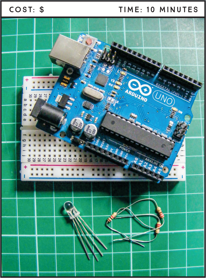
PARTS REQUIRED
Arduino board
Breadboard
Jumper wires
RGB common-cathode LED
3 220-ohm resistors
HOW IT WORKS
LEDs come in many different colors and forms, but one of the most useful is the RGB LED. As its name implies, an RGB LED is actually three LEDs in one: red, green, and blue (see Figure 5-1).
FIGURE 5-1: The primary colors of the RGB LED

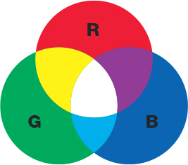
RGB is an additive color model, which means that by combining the light of two or more colors we can create other colors. Red, green, and blue are the additive primary colors used as the base for other colors, as shown in Figure 5-2.
FIGURE 5-2: RGB is an additive color model.
Let’s look at an RGB LED in a bit more detail in Figure 5-3.
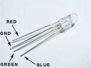
You’ll see that the RGB LED has four legs instead of the usual two: one each for red, green, and blue, and the fourth one is either the cathode or anode. We’ll be using a common-cathode RGB LED like the one in the figure, where the longest leg is the cathode and connects to ground.
We can use our RGB LED to create a random-color output that cycles through the colors of the rainbow, fading each one in and out. This lighting effect is used quite often in clubs or bars to create a relaxing mood. You could also place the LED in an opaque vase or box for a soothing night-light.
THE BUILD
Begin by placing the common-cathode RGB LED into your breadboard with the red leg in the hole to the left of the long GND (or cathode) leg. Connect a 220-ohm resistor to each of the three color legs.
NOTE
On some RGB LEDs the green and blue legs are the other way around.
Connect the red leg to Arduino pin 11, GND to Arduino GND, green to Arduino pin 10, and blue to Arduino pin 9.
COMMON-CATHODE RGB LED
ARDUINO
Red
Pin 11
GND
GND
Green
Pin 10
Blue
Pin 9
Confirm that your setup matches the circuit diagram in Figure 5-4, and upload the code in “The Sketch” on page 47.
FIGURE 5-4: The circuit diagram for the mood light

THE SKETCH
The sketch first sets Arduino pins 9, 10, and 11 as outputs. This sketch varies the brightness (power) value of each light on the RGB LED in turn by switching them on and off incredibly quickly—the longer an LED is lit for, the brighter it appears. To do this the Arduino uses a technique called pulse width modulation (PWM). The Arduino creates a pulse by switching the power on and off very quickly. The duration that the power is on or off (known as the pulse width) in the cycle determines the average output, and by varying this pulse width the Arduino can simulate voltages between full on (5 volts) and off (0 volts). If the signal from the Arduino is on for half the time and off for half, the average output will be 2.5 volts, halfway between 0 and 5. If the signal is on for 80 percent and off for 20 percent, the voltage is 4 volts, and so on.
We define an RGB value between 0 and 255, with an increment of 5 volts, to create a fade effect. In simple terms, each color of the LED brightens from 0 to 5 volts in sequence, and then fades out when it reaches its maximum value of 255. The Arduino can handle values between 0 and 1023 (1,024 values in total), but because this is such a high number we divide it by 4 and use 255 as the maximum LED value so the color change is more noticeable.
int redPin = 11; // Pin connected to red leg of the RGB LED
int greenPin = 10; // Pin connected to green leg of the RGB LED
int bluePin = 9; // Pin connected to blue leg of the RGB LED
void setup() {
setRgb(0, 0, 0); // Set all colors at 0
}
void loop() {
int Rgb[3]; // 3 RGB pins
Rgb[0] = 0; // A value for each
Rgb[1] = 0;
Rgb[2] = 0;
// Colors increase and decrease in value
for (int decrease = 0; decrease < 3; decrease += 1) {
int increase = decrease == 2 ? 0 : decrease + 1;
for (int i = 0; i < 255; i += 1) { // Fade the colors
Rgb[decrease] -= 1;
Rgb[increase] += 1;
setRgb(Rgb[0], Rgb[1], Rgb[2]);
delay(20);
}
}
}
void setRgb (int red, int green, int blue) {
analogWrite(redPin, red);
analogWrite(greenPin, green);
analogWrite(bluePin, blue);
}
TROUBLESHOOTING
Q. The code compiles, but the RGB LED does not light up as expected.
• If the RGB LED does not light at all, make sure you’ve connected the GND wire from the Arduino to the correct leg on the RGB LED—the long cathode leg—and that the Arduino has power connected.
• If you have a common-anode RGB LED, then you should connect the long leg to +5V on the Arduino. Check the data sheet for your part to find out which kind of RGB LED you have.
• If the colors don’t appear as expected, your RGB LED may have a different pin configuration; check your data sheet or try swapping the connections to the green and blue legs around.