11
Stepper Motor
In this project I’ll introduce you to a stepper motor (or step motor), set it up, and discuss how it works.

PARTS REQUIRED
Arduino board
Breadboard
Jumper wires
28BYJ-48 stepper motor with ULN2003 driver module
50k-ohm potentiometer
LIBRARY REQUIRED
Stepper
HOW IT WORKS
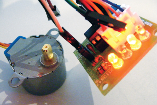
A stepper motor, like the one shown in Figure 11-1, is a direct current (DC) electric motor that divides a full rotation of the arm into a number of equal steps. Unlike the servomotor used in Project 10, this stepper motor turns 360 degrees and has the advantage of being able to position itself with great accuracy or rotate continuously.
FIGURE 11-1: A 28BYJ-48 stepper motor
The stepper motor’s data sheet will state the number of steps it performs per revolution; a step is just one movement within one revolution. A motor with 200 steps per revolution will turn through 360 degrees in 200 steps, or 1.8 degrees per step. Within a stepper motor there are two interlocked discs, similar to gears, with teeth of opposing magnetism that alternate and connect to the center shaft or rotor. The motor moves in steps when power is sent to its windings—a series of wire coils that become electromagnets when voltage is applied. When powered, these electromagnets attract or oppose the gear-shaped discs and rotate the shaft.
You can control the motor’s position and speed by commanding it to move to and hold at one of these steps. Since we know the angle each step represents, we can get accurate and precise turning angles and distance measurements. Stepper motors are commonly used in CD and DVD players and in 3D printers, where movements need to be very accurate.
When you’re looking to buy a stepper motor, there are a few things to consider. The first is whether or not it has a gearbox. A gearbox will improve the torque (moving power) but reduce the revolutions per minute (RPM, or speed).
The next consideration is whether the stepper motor is bipolar or unipolar. Bipolar motors switch polarity of the coils. Polarity is the direction the current flows; so if, for example, we reversed the 5V and GND connections, the motor would turn in the opposite direction. Bipolar motors have simpler windings but require more complicated drivers as they reverse the polarity for us. Unipolar motors essentially have a winding per polarity, but they can use simpler drivers. You can check whether your motor is bipolar or unipolar by looking at the connections: a bipolar motor has four connections, and a unipolar motor has five to eight connections. In this project we’re using a unipolar motor, the 28BYJ-48 stepper motor with the ULN2003 driver test module—a board that makes it easy to control the motor with the Arduino, like the module board for the LED matrix in Project 4. Some driver boards will have a slightly different setup, so I’d recommend getting the model of motor listed here for the project so you can follow the instructions closely.
Turning the potentiometer alters the angle of the stepper motor arm, so as you move the potentiometer to the left or right, the stepper motor arm will follow your input. (A potentiometer is a variable resistor with a knob.) The resistance of the potentiometer changes as you turn the knob. They are commonly used in electrical devices such as volume controls on audio equipment.
THE BUILD
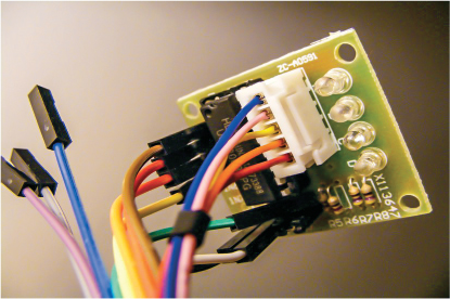
Connect the stepper motor to the driver board, as shown in Figure 11-2. From the outermost pin to the innermost pin in the middle of the board, connect the wires from the motor in the following order: blue, pink, yellow, orange, red. The connector can only be inserted in this way.
FIGURE 11-2: Connecting the stepper to the driver board
Connect the driver board pins 1, 2, 3, and 4 at the other end of the board directly to Arduino pins 8, 9, 10, and 11, respectively.
STEPPER DRIVER BOARD
ARDUINO
IN1
Pin 8
IN2
Pin 9
IN3
Pin 10
IN4
Pin 11
GND
GND
+5V
+5V
Insert a potentiometer into the breadboard, connecting its center pin to Arduino A0 and its outer two pins to Arduino +5V and GND in any order.
POTENTIOMETER
ARDUINO
Left pin
GND
Center pin
A0
Right pin
+5V
Connect the driver board GND and +5V to the breadboard GND and +5V, and connect the breadboard rails to the Arduino. Don’t forget to attach the power rails of the breadboard to GND and +5V too.
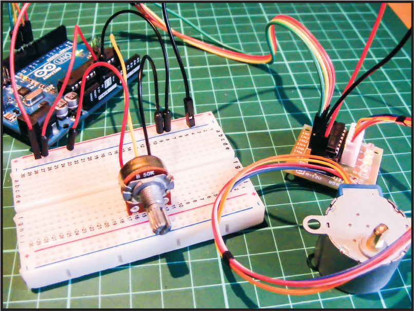
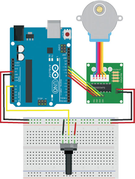
Make sure that your setup matches the final configuration shown in Figure 11-3, and upload the code in “The Sketch” below.
FIGURE 11-3: The circuit diagram for the stepper motor
THE SKETCH
This code comes with the Arduino IDE and can be found at File ▸ Examples ▸ Stepper ▸ MotorKnob. I’ve reproduced it here as you’ll see it in the IDE. It uses the built-in stepper library, <Stepper.h>. The potentiometer is connected to the Arduino A0 pin and gives a variable voltage depending on the turn of the potentiometer, which then controls the position of the stepper motor.
/* MotorKnob
* http://www.arduino.cc/en/Reference/Stepper
* This example code is in the public domain.
*/
#include <Stepper.h>
// Change this to the number of steps on your motor
#define STEPS 100
// Create an instance of the stepper class, specifying the number of
// steps of the motor and the pins it's attached to
Stepper stepper(STEPS, 8, 10, 9, 11);
// The previous reading from the analog input
int previous = 0;
void setup() {
// Set the speed of the motor to 700 RPM
stepper.setSpeed(30);
}
void loop() {
// Get the sensor value
int val = analogRead(0);
// Move a number of steps equal to change in the sensor reading
stepper.step(val - previous);
// Remember the previous value of the sensor
previous = val;
}
TROUBLESHOOTING
Q. The code compiles, but the stepper motor does not move.
• When you power the motor, lights should blink on the driver motor board. If they don’t, there’s an issue with power, so check that your setup matches the circuit diagram in Figure 11-3. Make sure the stepper motor connection is firmly inserted into the driver motor board—it can only go in one way.
• If the driver board lights but the motor does not move, check that the connections to the potentiometer are secure and match the tables shown earlier.