
Primer: Getting Started
Before you start building with the Arduino, there are a few things you need to know and do. First, let’s take a look at the hardware and software you’ll need for this book. Then, you’ll test out the Arduino with a simple LED project and get started with a few techniques that will come in handy, like soldering and downloading useful code libraries.
HARDWARE
First let’s look at the Arduino Uno board and a few pieces of hardware that you’ll use in almost every project.
The Arduino Uno
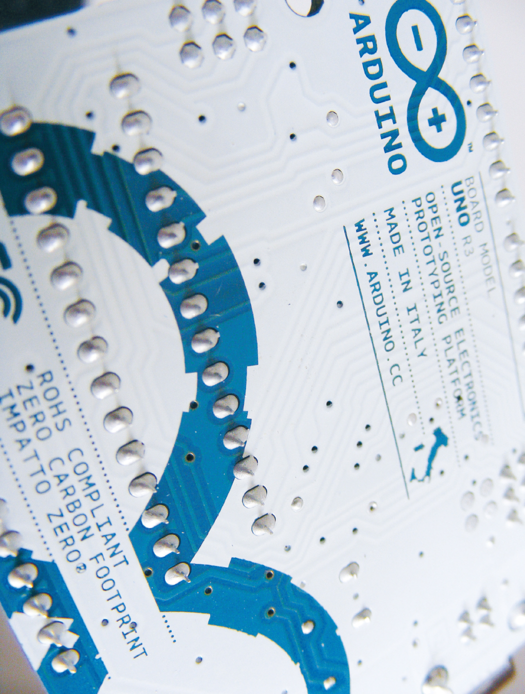
There are numerous types of Arduino boards available, but this book uses only the most popular one, the Arduino Uno shown in Figure 0-1. The Arduino Uno is open source (meaning its designs may be freely copied), so as well as the official board, which costs about $25, you will find numerous compatible clone boards for around $15.
FIGURE 0-1: The Arduino Uno board

The Arduino controls components you attach to it, like motors or LEDs, by sending information to them as output (information sent out from the Arduino). Data that the Arduino reads from a sensor is input (information going in to the Arduino). There are 14 digital input/output pins (pins 0–13) on the Arduino. Each can be set to either input or output (see “Arduino Pin Reference” on page 253 for a full pin reference table).
Power
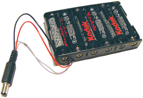
When you connect the Arduino Uno board to your PC to upload a program, it is powered from your computer’s USB port. When the Arduino is not linked to your PC, you can have it run independently by connecting it to a 9-volt AC adapter or 9-volt battery pack with a 2.1 mm jack, with the center pin connected to positive power as shown in Figure 0-2. Simply insert the jack into the power socket of the Arduino.
FIGURE 0-2: A 9-volt battery pack, which you can plug into the Arduino to give it power
Breadboards
A breadboard acts as a construction base for electronics prototyping. You’ll use a breadboard for all of the projects in this book instead of soldering parts together.
The name breadboard dates back to when electronics projects were created on wooden boards. Hobbyists hammered nails into the wood and wrapped wires around them to connect components without having to solder them permanently. Today’s breadboards are made of plastic with predrilled holes (called tie points) into which you insert components or wires, which are held in place by clips underneath. The tie points are connected by lengths of conductive material that run beneath the board, as shown in Figure 0-3.
FIGURE 0-3: Breadboard connections

Breadboards come in various sizes. To build the projects in this book, you’ll ideally need three breadboards: one full-size, typically with 830 holes; one half-size, with about 420 holes; and one mini board with 170 holes. The full-size breadboard is ideal for projects that use an LCD screen or a lot of components, and the half-size and mini boards are best for smaller projects. For the projects in this book, I recommend that you buy breadboards that look like the one shown in Figure 0-3, with red and blue lines and a center break between the holes.
TIP
It’s useful to use red wires for connections to 5V and black wires for connections to ground (GND). The rest of the wires can be your choice of color.
The main board area has 30 columns of tie points that are connected vertically, as shown in Figure 0-3. You’ll often have to position components so they straddle the breadboard’s center break to complete your circuit. This break helps to prevent components from short-circuiting, which can derail your project and even damage your components. You’ll learn more about this as you start to build.
The blue and red lines at the top and bottom are power rails that you use to power the components inserted in the main breadboard area (see Figure 0-4). The power rails connect all the holes in the rail horizontally; the red lines are for positive power and the blue lines for negative power (or ground, as you’ll often see it called).
FIGURE 0-4: Positive and negative breadboard rails
Jumper Wires
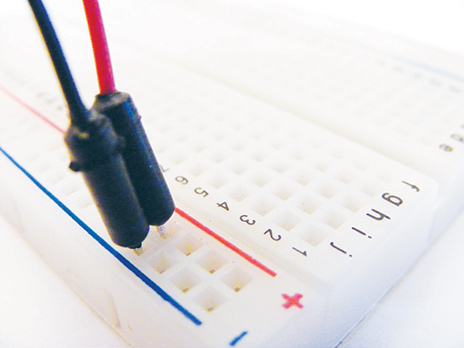
You’ll use jumper wires to make connections on the breadboard. Jumper wires are solid-core wire with a molded plastic holder on each end that makes it easier to insert and remove the wires. (You could use your own wire if you have it, but make sure to use solid-core wire—stranded wire is not strong enough to push into the hole clips.)
When you insert a jumper wire into a breadboard hole, it’s held in place from beneath the board by a small spring clip, making an electrical connection in that row. You can then place a component in an adjoining hole to help create a circuit, as shown in Figure 0-5.
FIGURE 0-5: An example breadboard circuit

NOTE
Because the IDE versions can change fairly quickly, I won’t take you through installing them, but installation should be straightforward and the instructions on the Arduino site are clear. All versions of the IDE and full details of how to install for your operating system are available at http://www.arduino.cc/.
PROGRAMMING THE ARDUINO
To make our projects do what we want, we need to write programs that give the Arduino instructions. We do so using the Arduino integrated development environment (IDE). The Arduino IDE is available to download free from http://www.arduino.cc/, and will run on Microsoft Windows, OS X, and Linux. It enables you to write computer programs (a set of step-by-step instructions, known as sketches in the Arduino world) that you then upload to the Arduino using a USB cable. Your Arduino will carry out the instructions based on its interaction with the outside world.
The IDE Interface
When you open the Arduino IDE, it should look similar to Figure 0-6. The IDE screen is divided into a toolbar at the top with buttons for the most commonly used functions; the sketch window in the center, where you’ll write or view your programs; and the Serial Output window at the bottom. The Serial Output window displays communication messages between your PC and the Arduino, and also lists any errors if your sketch doesn’t compile properly.

Arduino Sketches
I’ll give you the sketch for each project within the relevant project itself, and talk through it there. All of the sketches are available to download from http://www.nostarch.com/arduinohandbook2/.
Like any program, sketches are a very strict set of instructions and very sensitive to errors. It’s best to download the sketch and open the file in the IDE, rather than try to copy it from the book. To make sure it works correctly, click the green check mark at the top of the screen. This is the Verify button, and it checks for mistakes and tells you in the Serial Output window whether the sketch has compiled correctly.
Libraries
In the Arduino world a library is a piece of code that carries out a specific function. Rather than enter this same code repeatedly in your sketches wherever you need, you can simply add a command that borrows that code from the library. This shortcut saves time and makes it easy for you to connect to items such as a sensor, display, or module.
The Arduino IDE includes a number of built-in libraries—such as the LiquidCrystal library, which makes it easy to talk to LCD displays—and there are many more available online. To create the projects in the book, you’ll need to import the following libraries: PololuLedStrip, FastLED, HMC5883L, Keypad, Tone, Adafruit_GFX, Adafruit_SDD1306, NewPing, Adafruit Fingerprint Sensor, and Adafruit Motor Shield. You’ll find all of the libraries you need in the resources at http://www.nostarch.com/arduinohandbook2/.
Installing Libraries
Once you’ve downloaded the libraries, you’ll need to install them. To install a library in Arduino version 1.0.5 and higher, follow these steps:
Choose Sketch ▸ Include Library ▸ Add .ZIP Library.
Browse to the ZIP file you downloaded and select it. In older versions of Arduino, unzip the library file and put the whole folder and its contents into the sketchbook/libraries folder on Linux, My DocumentsArduinoLibraries on Windows, or Documents/Arduino/libraries on OS X.
To install a library manually, go to the ZIP file containing the library and uncompress it. For example, to install a library called keypad in a compressed file called keypad.zip, you would uncompress keypad.zip, which expands into a folder called keypad, which in turn contains files like keypad.cpp and keypad.h. Once the ZIP file is expanded, you would drag the keypad folder into the libraries folder on your operating system: sketchbook/libraries in Linux, My DocumentsArduinoLibraries on Windows, and Documents/Arduino/libraries on OS X. Then you’d restart the Arduino application.
Libraries are listed at the start of a sketch and are easily identified because they begin with the command #include. Library names are surrounded by < > and end with .h, as in this code to call the Servo library:
#include <Servo.h>
Go ahead and install the libraries you’ll need for the projects now to save yourself a bit of time later.
TESTING YOUR ARDUINO: BLINKING AN LED
Let’s begin our tour with the classic first Arduino project: blinking an LED (short for light-emitting diode, which is like a little light bulb). Not only is this the simplest way to make sure that your Arduino is working correctly, but it will also introduce you to a simple sketch. The Arduino can hold only one program at a time, so once you upload your sketch to your Arduino, that sketch will run every time the Arduino is switched on until you change it.
The Build
For this project we’ll use the Blink example sketch that comes with the IDE. The Blink program turns an LED on for 1 second and then off, repeatedly. The LED works only with current flowing in one direction, so its longer wire must connect to a positive power connection. LEDs require a current-limiting resistor or else the bulb may burn out. There is a built-in resistor in pin 13 of the Arduino that we’ll use.
Follow these steps to set up your test:
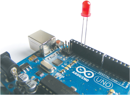
Insert the longer, positive leg of the LED to pin number 13 on the Arduino, as shown in Figure 0-7. Connect the shorter, negative wire to the GND pin next to pin 13.
FIGURE 0-7: The Blink project setup
Connect the Arduino to your computer with the USB cable.
Open the Arduino IDE on your computer, then choose File ▸ Examples ▸ Blinking LED from the drop-down menu. The sketch will appear in the main program area of the IDE.
➊// Blinking LED Project - This example code is in the public domain
➋ int led = 13;
➌ void setup() {
➍ pinMode(led, OUTPUT);
}
➎ void loop() {
➏ digitalWrite(led, HIGH);
➐ delay(1000);
➑ digitalWrite(led, LOW);
➒ delay(1000);
➓ }In the IDE, click the Verify button to check that the sketch is working correctly.
Click the Upload button to send the sketch to your Arduino. Running this code should make your LED flash on and off.
Understanding the Sketch
Here’s what’s happening on each line of the sketch:
➊ This is a comment. Any line in your program starting with // is meant to be read by the user only and is ignored by the Arduino, so use this technique to enter notes and describe your code (called commenting your code). If a comment extends beyond one line, start the first line with /* and end the comment with */. Everything in between will be ignored by the Arduino.
➋ This gives pin 13 the name led. Every mention of led in the sketch will refer to pin 13.
➌ The code between the curly brackets, {}, will run once when the program starts. The open curly bracket, {, begins the setup code.
➍ This tells the Arduino that pin 13 is an output pin, indicating that we want to send power to the LED from the Arduino. The closing curly bracket, }, ends the setup code.
➎ This creates a loop. Everything between the curly brackets, {}, after the loop() statement will run once the Arduino is powered on and then repeat until it is powered off.
➏ This tells the Arduino to set led (pin 13) to HIGH, which sends power to that pin. Think of it as switching the pin on. In this sketch, this turns on the LED.
➐ This tells the Arduino to wait for 1 second. Time on the Arduino is measured in milliseconds, so 1 second = 1,000 milliseconds.
➑ This tells the Arduino to set led (pin 13) to LOW, which removes power and switches off the pin. This turns off the LED.
➒ Again the Arduino is told to wait for 1 second.
➓ This closing curly bracket ends the loop. All code after the initial setup must be enclosed within curly brackets. A missing bracket can easily be overlooked and is a common cause of errors that will prevent your sketch from compiling correctly. After this curly bracket, the code goes back to the start of the loop at ➎.
Now that you’ve tested your Arduino and understand how a sketch works and how to upload it, we’ll take a look at the components you’ll need to carry out all of the projects in this book. “Components” on page 238 has more details about each component, what it looks like, and what it does.
PROJECT COMPONENT LIST
This is a complete list of the items you’ll need in order to complete the projects in this book. The most important part, of course, is the Arduino board itself, and all projects use the Arduino Uno R3 version. Only the official boards are named Arduino, but you’ll find compatible clone boards from companies like SlicMicro, Sainsmart, and Adafruit. (You’ll find a list of official suppliers at http://arduino.cc/en/Main/Buy/.)
You can buy each item individually, but I suggest buying an electronics hobby starter kit or Arduino kit, which will provide you with several of the items here. See the “Retailer List” on page 249 for a list of suggested suppliers. Alternatively, each project begins with a list of the required parts, so you can flip to a project that interests you and obtain just those components if you’d like.
1 Arduino Uno R3 (or compatible)
1 9V battery pack with 2.1 mm jack for 6 AA batteries
1 9V battery snap and battery
3 breadboards: 1 full-size, 1 half-size, 1 mini
50 male-to-male jumper wires
10 female-to-male jumper wires
Solid-core wire
9 220-ohm resistors
4 10k-ohm resistors
8 1k-ohm resistors
40 5 mm LEDs in red, green, yellow, blue (10 of each)
1 RGB common-cathode LED
1 RGB LED strip (WS2812B 5V 32-LED strip)
1 Adafruit NeoPixel ring with 16 RGB LEDs
1 HMC5883L three-axis sensor
2 50k-ohm potentiometers
1 10k-ohm potentiometer
8 momentary tactile pushbuttons
1 seven-segment, single-digit common-cathode LED
1 piezo sounder
1 3.5 mm female headphone jack
1 Tower Pro SG90 9g servomotor
1 photoresistor (light-dependent resistor, or LDR)
1 28BYJ-48 stepper motor with ULN2003 driver module
1 HC-SR04 ultrasonic sensor
1 3×4 membrane keypad
1 LM35 temperature sensor
1 12V mini computer cooling fan
1 5V single-channel relay module
1 HD44780 16×2 LCD screen
1 Nokia 5110 LCD screen
1 serial LCD screen module
1 OLED monochrome screen (128×64)
1 8×8 LED Maxim 7219 matrix module
1 Keyes MQ3 alcohol sensor module
1 optical fingerprint sensor (ZFM-20 series)
1 L293d motor shield
1 robot chassis kit, including two DC motors and wheels, center wheel, base, and fittings
1 Ethernet shield W5100 LAN expansion board
1 Ethernet cable
1 WLToys V959-18 Water Jet Pistol
1 HC-06 Bluetooth module
1 Ublox NEO-6M GPS module aircraft flight controller and antenna
QUICK SOLDERING GUIDE
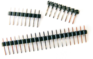
The majority of the projects in this book do not requiring soldering, but there are a few components that may come with their header pins (Figure 0-8) unattached for ease of transport. Header pins come in strips that can be easily snapped to the size needed.
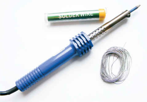
For example, the GPS module used in Project 25 doesn’t come with the pins attached, so I’ll explain how to solder those in place. A general-purpose, 30-watt soldering iron with a fine tip should meet your needs. It is worthwhile to buy a kit that includes a soldering iron, stand, and solder (Figure 0-9).
Plug in your soldering iron and wait at least 5 minutes for it to reach operating temperature.
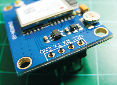
To solder, break off a strip of header pins with the number you need. Insert them into the module as shown in Figure 0-10.
FIGURE 0-10: Insert the header pins into the module.
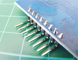
Now solder the pins in place, starting with the leftmost pin. Hold the heated tip of the soldering iron to both the pin and module contact at the same time. You only need to hold it there for about 2 seconds. While holding the iron in place, add solder to the area; the solder should melt and flow and create a join. Note that you do not apply solder directly to the iron, only to the joint you are soldering. Quickly remove both the iron and solder—more than a couple of seconds of contact could damage your components.
A good solder joint should look like a shiny cone (Figure 0-11). With a little bit of practice, you will be able to solder cleanly in no time at all.
FIGURE 0-11: Solder joins should look like this.
Safety First
Soldering irons get very, very hot and should be used with extreme care under adult supervision. Here are a few safety tips:
• Be sure to use a stand and never lay a hot soldering iron down on a table.
• Solder in a well-ventilated room. The fumes released from melting solder can be harmful.
• Keep flammable materials away from your work area.
• Keep equipment out of reach of children.
• Wear eye protection.
• Wait for a soldering iron to cool down completely before storing it.