
23
Internet-Controlled LED
In this project we’ll use an ethernet shield to connect our Arduino to the internet and control an LED from a web browser.
PARTS REQUIRED
Arduino board
Breadboard
Jumper wires
Ethernet shield W5100 LAN expansion board
Ethernet cable
LED
220-ohm resistor
LIBRARIES REQUIRED
SPI
Ethernet
The Internet of Things (IoT) is revolutionizing our use of everyday items. The term refers to objects or smart devices connected through a network, usually involving the internet. This allows us to control devices remotely, from inside or outside the house! Amazon Echo and Google Home are taking things further by allowing a multitude of devices to be connected and controlled via a central hub, even if you aren’t at home. We’ll create our own IoT project in its most basic form to demonstrate the principles involved.
HOW IT WORKS
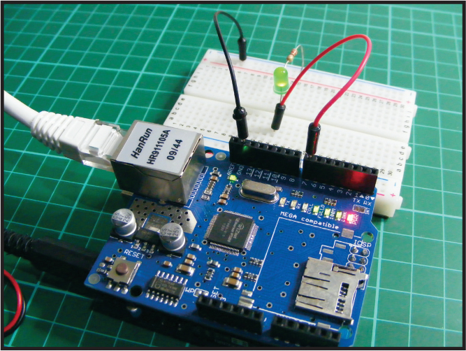
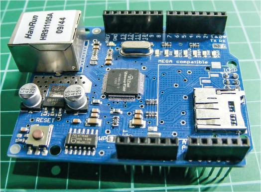
The Ethernet shield W5100 LAN expansion board, shown in Figure 23-1, fits directly on top of the Arduino to provide additional functionality to the board. We’ll use the Ethernet library built into the Arduino IDE to connect our board to the internet via an Ethernet cable, as shown in Figure 23-2.

The library allows the Arduino to act as a server to accept incoming commands, a client to send them out, or both. The shield communicates with the Arduino using the Serial Peripheral Interface (SPI) connections. On the Arduino Uno the SPI connections are on digital pins 10, 11, 12, and 13. In our project the Arduino will use both functions to send information to the internet in the form of a simple web page and accept commands from this page to control an LED. Buttons on the web page will allow us to switch the LED on or off as long as the Arduino is powered and connected to the internet.
SETTING UP YOUR ETHERNET CONNECTION
You need to know the MAC address of your shield for this project to work. A MAC address is a unique number assigned to devices for communication and is used as a network address for Ethernet and Wi-Fi. If you have a newer shield, the MAC address will be printed on a product sticker. If you have an older generic Ethernet shield like the one we are using, you can use the MAC address 0xDE, 0xAD, 0xBE, 0xEF, 0xFE, 0xED for this project.
For communication, we’ll use port 80, the default for HTTP. Short for HyperText Transfer Protocol, HTTP is the set of rules for transferring data over the internet. In this instance port 80 handles the transfer of data to a web page.
Our sketch includes some HTML (HyperText Markup Language) code, which tells a web browser how to display an internet page. If you right-click on any web page and select Inspect, you can see some of the HTML code behind that page.
The section of our sketch that includes HTML code is as follows and produces the web page displayed in Figure 23-3.
client.println("HTTP/1.1 200 OK");
client.println("Content-Type: text/html");
client.println();
client.print("<center><br><h1>Internet Controlled LED</h1><br><br><br><FORM>");
client.print("<P> <INPUT type="submit" name="status"value="ON">");
client.print("<P> <INPUT type="submit" name="status"value="OFF">");
client.print("</FORM></center>");
FIGURE 23-3: Our simple web page to control the LED

THE BUILD
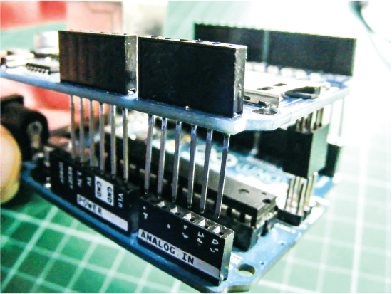
Attach the Ethernet shield on top of the Arduino board as shown in Figure 23-4. The board fits directly on top of the Arduino, so gently press the legs of the shield in place with the holes of the Arduino beneath.
FIGURE 23-4: Attach the Ethernet shield on top of the Arduino board.
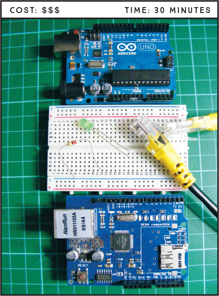
Insert the LED into the breadboard with the legs straddling the center break of the board. Then, as shown in the following table, connect the shorter, negative leg of the LED to the GND rail of the breadboard via a 220-ohm resistor, and connect the longer, positive leg of the LED to pin 7 on the Arduino/Ethernet shield. Connect the GND rail of the breadboard to Arduino GND.
LED
ARDUINO
Negative leg
GND via 220-ohm resistor
Positive leg
Pin 7
With the Ethernet shield attached on top of the Arduino, connect the shield to your router with the Ethernet cable.
NOTE
Take note of your IP address; it will be different from mine shown in Figure 23-5.
Attach the Arduino to your PC and upload the code at the end of the project using the IDE. Once the code is uploaded, open the IDE Serial Monitor in order to ascertain the IP address—a unique string of numbers to identify a device attached to the internet—of the Arduino, which is acting as our server. You should see something similar to Figure 23-5.
FIGURE 23-5: The IP address of the Arduino shield will be shown in the Serial Monitor.

Open any web browser and enter your IP address. You should see a web page with an On and an Off button, as shown earlier in Figure 23-3. Press the On button to light the LED and press the Off button to switch it off.
This project will also work when you are not connected to your local network, as long as you have port 80 open on your internet router. Many internet service providers (ISPs) have this port blocked for security reasons, so follow the instructions from your ISP to change this if required.
WARNING
Carry out this function only if you are aware of the security risks and how to minimize them.
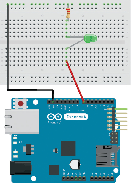
Confirm that your setup matches the circuit diagram in Figure 23-6, and then upload the code in “The Sketch” on page 208.
FIGURE 23-6: The circuit diagram for the internet-controlled LED
THE SKETCH
The sketch calls on the SPI and Ethernet libraries to control communication with the internet. We define the MAC address for the shield. This is the line you need to change if your shield came with its own MAC address; if not, the address given earlier in this project and shown in the code should work for you. We then set the server to use port 80 and define pin 7 on the Arduino as the LED pin.
The setup defines the LED pin as an output, begins the Ethernet shield, and starts serial communication so we can see the IP address of our server. The loop sets up our web page to the browser once it is called and waits for an input on the browser task bar. When the On button is pressed, the server tells the Arduino to set the LED pin as HIGH and the LED will light. When the Off button is pressed, the power to the LED is LOW and the LED will turn off.
You could easily change the LED for a relay switch such as the one used in Project 12 to control a larger-voltage device.
#include <SPI.h>
#include <Ethernet.h>
// MAC address for shield
byte mac[] = {0xDE, 0xAD, 0xBE, 0xEF, 0xFE, 0xED};
EthernetServer server(80); // Using port 80
int led = 7; // LED attached to pin 7
void setup() {
pinMode(led, OUTPUT); // LED set as an output
Ethernet.begin(mac); // Start the Ethernet shield
server.begin();
Serial.begin(9600); // Start serial communication
Serial.println("Server address:"); // Print server address
// (Arduino shield)
Serial.println(Ethernet.localIP());
}
void loop() {
EthernetClient client = server.available();
if (client) {
boolean currentLineIsBlank = true;
String buffer = "";
while (client.connected()) {
if (client.available()) {
char c = client.read(); // Read from the Ethernet shield
buffer += c; // Add character to string buffer
// Client sent request, now waiting for response
if (c == '
' && currentLineIsBlank) {
client.println("HTTP/1.1 200 OK"); // HTTP response
client.println("Content-Type: text/html");
client.println(); // HTML code
client.print("<center><br><h1>Internet Controlled LED</h1><br><br><br><FORM>");
client.print("<P> <INPUT type="submit" name="status"value="ON">");
client.print("<P> <INPUT type="submit" name="status"value="OFF">");
client.print("</FORM></center>");
break;
}
if (c == '
') {
currentLineIsBlank = true;
buffer = "";
}
else if (c == '
') { // Command from webpage
// Did the on button get pressed
if (buffer.indexOf("GET /?status=ON") >= 0)
digitalWrite(led, HIGH);
// Did the off button get pressed
if (buffer.indexOf("GET /?status=OFF") >= 0)
digitalWrite(led, LOW);
}
else {
currentLineIsBlank = false;
}
}
}
client.stop(); // End server
}
}
TROUBLESHOOTING
Q. The code compiles, but the LED does not light as expected.
• First, make sure you’ve connected the GND wire from the Arduino to the correct breadboard power rail and that the Arduino has power connected.
• Check that the resistor is inserted fully and lines up with the corresponding LED leg.
• Try checking that the project is working by connecting to your local area network and using that PC to connect to the Arduino.
Q. You receive an error when calling the web page.
• Make sure you have entered the IP address of the server exactly as you read it in the steps given earlier.
• It is best to check the project is working by connecting to your local area network and using that PC to connect to the Arduino.
• If the project worked when you connected it to your local area network, but you receive an HTTP 403 error when connecting to the internet externally, then your ISP is blocking incoming traffic. You could add port forwarding to your router for port 80. This will differ for every device, so check with your ISP for detailed instructions. Do a quick internet search with your ISP and “port forwarding” as terms and follow the instructions, but be aware: this can compromise the security of your PC and should be done only if you understand the risks and are able to protect your network.