Components
This section gives you some more information on the components used in this book. Each component is accompanied by a photo and a few details for quick reference and identification. At the end, I’ve also included a handy list of retailers to buy the parts from and a quick lesson on reading resistor values.
COMPONENTS GUIDE
The components are listed in the order in which they appear in the book. Many of the items can be found with a simple search on websites like eBay and Amazon, but a list of specialist suppliers is also provided in the “Retailer List” on page 249.
Arduino Uno R3
The Arduino Uno R3 microcontroller board is the main component for the book and the brain for all your projects.

• Quantity: 1
• Connections: 14
• Projects: All
9V Battery Pack
The 9V battery pack with a 2.1 mm jack for 6 AA batteries plugs into the power port on the Arduino and can be used to power your projects. Note that the Arduino can also be powered through the USB cable.
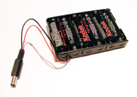
• Quantity: 1
• Connections: 1
• Projects: Optional for all
Breadboard
The breadboard is a prototyping board used to connect components together to create your projects. See the primer for more details.
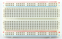
• Quantity: 1 full-size board, 1 half-size board, 1 mini board
• Connections: 940 on a full board, 420 on a half board, 170 on a mini board
• Projects: All except Projects 4, 6, 7, 16, 19, 22, and 25
LED
An LED, or light-emitting diode, is a small bulb that emits light when a low current is passed through it. It has two legs, the longer of which is the positive connection. LEDs generally require a resistor or they may burn out. LEDs are polarized, meaning current flows only in one direction.
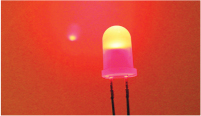
• Quantity: 40 (10 red, 10 blue, 10 yellow, 10 green)
• Connections: 2
• Projects: 1, 2, 9, 15, 17, 21, 23, 24
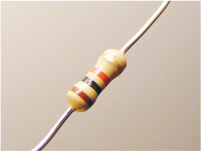
Resistor
Resistors restrict the amount of current that can flow through a circuit to prevent components from overloading. A resistor looks like a cylinder with colored bands and a wire extending from each end. The resistance value is indicated by a color code—see “Decoding Resistor Values” on page 250 for more details. Check the value carefully, as it can be easy to choose the wrong one. Resistors come in four-, five-, and six-band varieties, so be aware that, for example, a four-band 220-ohm resistor can look slightly different from a five-band resistor of the same value.
• Quantity: 9 220-ohm, 4 10k-ohm, 8 1k-ohm
• Connections: 2
• Projects: 1–3, 5, 8–10, 15, 17, 18, 21, 23, 24
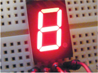
Seven-Segment LED Display
A seven-segment LED display forms a digit or character using LED segments, and is often used to display numbers for counters, clocks, or timers. You can get single-digit to eight-digit displays, and four-digit displays are commonly used for digital clocks.
• Quantity: 1
• Connections: 10
• Project: 3
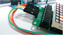
8×8 LED Maxim 7219 Matrix Module
This prebuilt 8×8 LED matrix module needs only five pins connected to your Arduino to work.
• Quantity: 1
• Connections: 5
• Project: 4
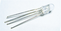
RGB LED
An RGB LED combines three colors—red, green, and blue—to make any color of the rainbow. It is a clear LED with four legs, each of which needs a resistor to limit the current and prevent the LED from burning out. The longest leg is either the common cathode or anode.
• Quantity: 1
• Connections: 4
• Project: 5
RGB LED Strip (WS2812B 5V 32-LED Strip)
LED strips come in single-color or multicolored varieties, and can differ in how the individual LEDs are controlled. Single-color, or multicolor nonaddressable, strips can light only one color at a time. RGB multicolored strips are generally addressable, which means each LED has its own chip and can be individually controlled, allowing multiple colors to light simultaneously.

• Quantity: 1
• Connections: 3
• Project: 6
Adafruit NeoPixel Ring with 16 RGB LEDs
The Adafruit NeoPixel ring has 16 RGB surface-mounted LEDs, each of which is addressable, allowing you to control each LED separately.
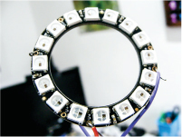
• Quantity: 1
• Connections: 3
• Project: 7
HMC5883L Three-Axis Sensor
The HMC5883L three-axis sensor is a multichip module used for sensing magnetic fields—we use it to detect magnetic north to act as a compass. The module may require you to solder header pins.
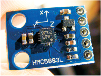
• Quantity: 1
• Connections: 4
• Project: 7
Pushbutton
A pushbutton is a simple switch that makes a connection when pushed. Also known as a momentary switch, a pushbutton connects a circuit when pushed in, and spring backs to break the connection when released. Pushbuttons vary in size, but most have four pins.
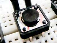
• Quantity: 8
• Connections: 4
• Project: 8
Piezo Sounder
The piezo sounder is a very basic speaker often used in inexpensive toys. A pulse of current causes it to click extremely quickly, and a stream of pulses emits a tone. The piezo sounder often looks like a small black box with two wires. Taken out of the case, it looks like a small, gold disc.
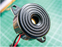
• Quantity: 1
• Connections: 2
• Projects: 8, 15
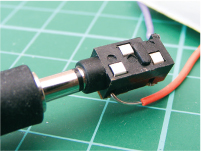
3.5 mm Female Headphone Jack
The 3.5 mm female headphone jack is a simple jack that allows you to connect audio devices to your Arduino. It can be purchased on its own or reclaimed from a dollar-store radio.
• Quantity: 1
• Connections: 3
• Project: 9
Servomotor
A servomotor is a motor with an arm attachment that you can position to specific angles by sending the servo a coded signal. The motor is in a small box with three wires and an output shaft to which you can attach the arm, known as a horn.
This book uses the Tower Pro SG90 9g servomotor, which turns 180 degrees; others are continuous and turn the full 360 degrees.

• Quantity: 1
• Connections: 3
• Projects: 10, 21, 22
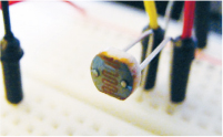
Photoresistor
A photoresistor, also referred to as a light-dependent resistor or a diode, detects light levels by producing a variable resistance depending on the amount of light falling on it. There are different styles, but it usually looks like a small, clear oval with wavy lines and two legs. You will need to calibrate your photoresistor to determine light levels before using it in a program.
• Quantity: 1
• Connections: 2
• Project: 10
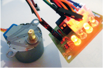
28BYJ-48 Stepper Motor with ULN2003 Driver Module
A stepper motor is a DC electric motor that divides a full 360-degree rotation of the arm into a number of equal steps for heightened control. We’re using the 28BYJ-48 stepper motor, which comes with a ULN2003 driver module to control it.
• Quantity: 1
• Connections: 5
• Project: 11
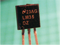
LM35 Temperature Sensor
The LM35 temperature sensor detects the temperature and sends the reading as a voltage value to the Arduino so we can measure heat.
• Quantity: 1
• Connections: 3
• Projects: 12, 14
12V Mini Computer Cooling Fan
A 12V mini computer cooling fan is the cooling fan used internally in a computer. We are using a 4 cm × 4 cm fan, but you could use a larger one if required. You could also reclaim one from an old PC, as long as it is no longer used.
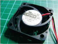
• Quantity: 1
• Connections: 2
• Project: 12
5V Single-Channel Relay Module
A relay is an electronically operated switch that, in this case, uses an electromagnet to mechanically open or close a circuit.
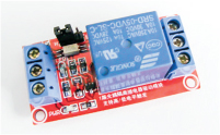
• Quantity: 1
• Connections: 6
• Project: 12
Potentiometer
A potentiometer is a resistor whose value you can vary to manipulate the voltage flowing through it, allowing you to control how much power goes to a component. It has a knob that you can turn and three pins at the bottom. The center pin is the control pin, with power to either side. It’s commonly used to control an output such as the volume on a radio. You connect power to pins 1 and 3, and it doesn’t matter which way they are connected.

• Quantity: 2 50k-ohm, 1 10k-ohm
• Connections: 3
• Projects: 11, 13–15, 18
LCD Screen
An LCD (liquid crystal display) screen is a display screen for outputting characters or images. It is composed of two sheets of polarizing material with a liquid crystal solution between them. Passing current through the liquid crystal makes it opaque, creating an image against a backlight.
Screens come in various dimensions. The one shown here is an HD44780 16×2 (16 characters × 2 lines) and has 16 connections.
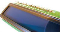
• Quantity: 1
• Connections: 16
• Projects: 13–16
Ultrasonic Sensor
An ultrasonic sensor sends out a signal (often referred to as a ping), which bounces off an object and is returned to the sensor. Distance is calculated from the time the signal takes to return once it has been sent. The sensor used in this book is the HC-SR04 ultrasonic sensor, a module board with two round sensors and four pins.
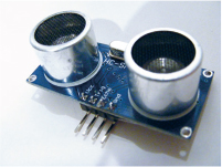
• Quantity: 1
• Connections: 4
• Projects: 13, 17, 20, 22
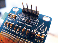
Keypad
A 3×4 membrane keypad is basically a series of switches. The example shown here has 12 pushbuttons connected in series, but a 16-button version is also available. Of the seven connections, four control the rows and three control the columns. The Arduino will replicate the number of the button pressed.

• Quantity: 1
• Connections: 7
• Project: 15
Serial LCD Screen Module
This 16×2 LCD screen has a serial module attached and thus requires only power and two pins connected to the Arduino.
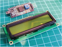
• Quantity: 1
• Connections: 4
• Project: 16
Nokia 5110 LCD Screen
This is a Nokia 84×48-pixel screen that, accounting for spaces between the characters, gives us a 12×6-character screen. It works similarly to the LCD screen in Project 13, by sending current through the liquid crystal from the Arduino at certain pixels to form letters or images.
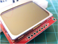
• Quantity: 1
• Connections: 8
• Project: 18
OLED Monochrome Screen (128×64)
The OLED (organic light-emitting diode) screen is a light-emitting technology composed of a thin, multilayered organic film placed between an anode and cathode. The one we use in this book has a 128×64 screen size.
• Quantity: 1
• Connections: 4
• Projects: 19, 25
Keyes MQ3 Alcohol Sensor Module
The MQ3 is a gas sensor sensitive to alcohol and ethanol. We use it in the breathalyzer in Project 19.
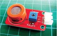
• Quantity: 1
• Connections: 3
• Project: 19
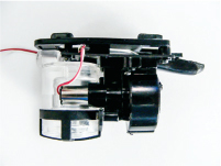
WLToys V959-18 Water Jet Pistol
The V959-18 water jet pistol comprises a small reservoir to hold water and a mini pump that pushes water through a nozzle.
• Quantity: 1
• Connections: 2
• Project: 20
Optical Fingerprint Sensor (ZFM-20 Series)
The ZFM-20 fingerprint sensor is a fingerprint comparison module that takes a photograph of a fingerprint and adds it to its database, allowing you to check if a new fingerprint matches one stored there. The sensor can hold up to 162 fingerprints.

• Quantity: 1
• Connections: 4
• Project: 21
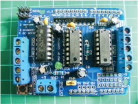
L293d Motor Shield
The L293d motor shield is a module for controlling motors that we use for our robot in Project 22.
• Quantity: 1
• Connections: fits on top of the Arduino
• Project: 22
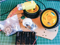
Robot Chassis Kit
If you search online for “Arduino robot kit,” you should be able to find a kit that contains two DC motors and wheels, a base plate, a battery pack, a center wheel, and the fittings needed to build an Arduino robot. The kit I bought was specifically named the “2WD Smart Motor Robot Car Chassis Kit for Arduino 1:48.”
• Quantity: 1
• Connections: 4 (2 for each motor)
• Project: 22
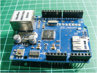
Ethernet Shield W5100 LAN Expansion Board
The Ethernet shield W5100 LAN expansion board fits directly on top of the Arduino to provide additional functionality, such as a web server or client that allows the Arduino to connect to a network.
• Quantity: 1
• Connections: multiple
• Project: 23
Ethernet Cable
An Ethernet cable transmits data between an internet connection or network and a device.

• Quantity: 1
• Connections: 1
• Project: 23
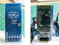
HC-06 Bluetooth Module
The HC-06 module provides Bluetooth wireless capabilities so the Arduino can transmit radio waves to exchange data over short distances. Smartphones, laptops, and multimedia devices such as speakers use Bluetooth technology as a common standard.
• Quantity: 1
• Connections: 4
• Project: 24
Ublox NEO-6M GPS Module Aircraft Flight Controller and Antenna
The Ublox NEO-6M GPS module is a tracking device that connects top GPS satellites, generally used to track the position of model aircraft or drones. The module is widely available from the sources listed here, or you can simply search for “Ublox NEO-6M GPS module” online. Make sure to get a module that also comes with a GPS antenna.

• Quantity: 1
• Connections: 5, including antenna
• Project: 25
RETAILER LIST
As mentioned earlier, most electronic components can be found on generic sites like Amazon or eBay, but if you have trouble finding anything, the retailers listed here should be able to help.
US Retailers
Adafruit https://www.adafruit.com/
DigiKey http://www.digikey.com/
Jameco Electronics http://www.jameco.com/
MCM http://www.mcmelectronics.com/
Newark http://www.newark.com/
RS Components http://www.rs-components.com/
Seeed Studio https://www.seeedstudio.com/
SparkFun https://www.sparkfun.com/
Australian Retailers
Core Electronics https://core-electronics.com.au/arduino.html
Little Bird Electronics http://www.littlebirdelectronics.com.au/
European Retailers
Electronic Sweet Pea’s http://www.sweetpeas.se/
Element 14 http://www.element14.com/
Farnell http://www.farnell.com/
UK Retailers
4tronix http://www.4tronix.co.uk/store/
Cool Components http://www.coolcomponents.co.uk/
Hobby Components https://www.hobbycomponents.com/
Mallinson Electrical http://www.mallinson-electrical.com/shop/
Maplin http://www.maplin.co.uk/
Oomlout http://oomlout.co.uk/
The Pi Hut http://thepihut.com/
Proto-pic http://proto-pic.co.uk/
Rapid Electronics http://www.rapidonline.com/
RS http://uk.rs-online.com/web/
Spiratronics http://spiratronics.com/
DECODING RESISTOR VALUES
In most of the projects in this book we’ve used resistors. Resistors are electrical components that limit the amount of current allowed through a circuit (measured in ohms). They are used to protect components, like LEDs, from overloading and burning out. The value of a resistor is identified by colored bands on the body. Resistors can have four, five, or six colored bands.
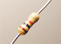
It's important to be able to determine the value of a resistor so that you know you’re using the correct one in your project. Let’s try to determine the value of the four-band resistor shown in Figure B-1.
FIGURE B-1: A four-band resistor
Viewing the resistor with the silver or gold band on the right, note the order of the colors from left to right. If the resistor has no silver or gold band, make sure the side with the three colored bands is on the left.
Use Table B-1 to determine the value of the resistor.
TABLE B-1: Calculating Resistor Values
COLOR |
FIRST BAND |
SECOND BAND |
THIRD BAND |
MULTIPLIER |
TOLERANCE |
Black |
0 |
0 |
0 |
1Ω |
|
Brown |
1 |
1 |
1 |
10Ω |
+/–1% |
Red |
2 |
2 |
2 |
100Ω |
+/–2% |
Orange |
3 |
3 |
3 |
1KΩ |
|
Yellow |
4 |
4 |
4 |
10KΩ |
|
Green |
5 |
5 |
5 |
100KΩ |
+/–0.5% |
Blue |
6 |
6 |
6 |
1MΩ |
+/–0.25% |
Violet |
7 |
7 |
7 |
10MΩ |
+/–0.10% |
Gray |
8 |
8 |
8 |
|
+/–0.05% |
White |
9 |
9 |
9 |
|
|
Gold |
|
|
|
0.1Ω |
+/–5% |
Silver |
|
|
|
0.01Ω |
+/–10% |
The first and second bands give you the numerical value, the third band tells you how many zeros to add to that number, and the fourth band tells you the tolerance—that is, how much the actual value can vary from the intended value.
NOTE
While the band that denotes the tolerance is most commonly silver or gold, it can be any of the other colors that has a percentage listed in the tolerance column. If you have a resistor with a tolerance band that isn’t silver or gold, there should be a small gap between the value bands and the tolerance band so you can tell which it is.
So, for the resistor in Figure B-1:
• First band is brown (1) = 1.
• Second band is black (0) = 0.
• Third band is red (2) = 00 (2 is the number of zeros).
• Fourth band is gold, so the tolerance (accuracy) is +/– 5 percent.
So this resistor is 1,000 ohms or 1 kilohm, with a tolerance of 5 percent, meaning that the actual value can be up to 5 percent more or less than 1 kilohm. We can do the same calculation for a five- or six-band resistor.
If you’re ever unsure of a resistor’s value, you can look it up by doing a quick online search of the colored bands on the resistor’s body. Just make sure to list the colors in the correct order, reading them from left to right, with the tolerance band on the right.