
16
Serial LCD Screen
In this project we’ll take a 16×2 character LCD screen and a serial module to create a serial LCD that’s controlled by only two wires.

PARTS REQUIRED
Arduino board
Female-to-male jumper wires
HD44780 16×2 LCD screen
Serial LCD screen module
LIBRARIES REQUIRED
Wire
LiquidCrystal_I2C
HOW IT WORKS
LCD screens are very useful in projects, but they use up a lot of pins on the Arduino. This means that if you’re incorporating them into a more complex project, you might run out of pins. Thankfully there is a solution: use a serial LCD screen. Serial LCDs use the communication protocol I2C, which stands for Inter-Integrated Circuit, and differ from normal 16×2 LCD screens in that they can be controlled by your Arduino with only power and two pins.
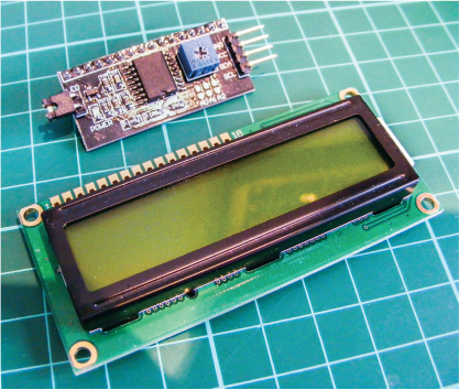
Serial LCD screens usually come in kit form and require you to solder header pins, which I’ll cover later in the chapter. You’ll usually receive the 16×2 LCD screen and the serial module separately, as shown in Figure 16-1.
FIGURE 16-1: 16×2 LCD screen and serial module
PREPARING THE SERIAL LCD SCREEN
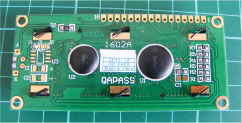
The serial module has a strip of 16 header pins already attached to one side. Turn the LCD screen over and you’ll see 16 corresponding holes, as shown in Figure 16-2.
FIGURE 16-2: The reverse side of the LCD screen
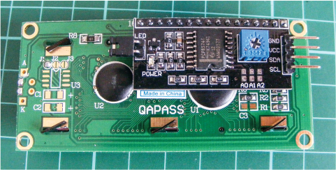
Place the serial controller header pins into those holes, as shown in Figure 16-3.
FIGURE 16-3: Insert the serial module into the LCD screen holes.
Carefully add a small amount of solder to each of the pins to make a connection and hold the serial monitor to the screen. Turn to the primer for a quick soldering guide.
THE BUILD
Your serial LCD screen has an assigned address that your Arduino needs in order to communicate with it. The addresses differ depending on the make, so you need to check the address of your specific screen, as you’ll need it for the sketch later. To check the address, connect the LCD screen to your Arduino and run a quick sketch to scan the module—or you could also refer to the data sheet for your screen.
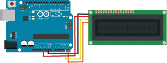
Connect your female-to-male jumper wires to the four pins on the controller for the LCD screen.
Wire up the serial LCD screen to the Arduino with GND to GND, VCC to +5V, SDA to Arduino pin A4, and SCL to Arduino pin A5, as shown in the following table and the circuit diagram in Figure 16-4.
SERIAL LCD SCREEN
ARDUINO
GND
GND
VCC
+5V
SDA
Pin A4 (SDA)
SCL
Pin A5 (SCL)
FIGURE 16-4: The circuit diagram for the serial LCD screen
Upload the following sketch to the Arduino. We’ll get the address in hexadecimal, a number system that uses letters and numbers in an abbreviated form to represent a much larger number.
#include <Wire.h>
void setup() {
Wire.begin();
Serial.begin(9600);
Serial.println("I2C Scanner");
}
void loop() {
byte error, address;
int nDevices;
Serial.println("Scanning...");
nDevices = 0;
for (address = 1; address < 127; address++) {
Wire.beginTransmission(address);
error = Wire.endTransmission();
if (error == 0) {
Serial.print("I2C device found at address 0x");
if (address < 16)
Serial.print("0");
Serial.print(address, HEX);
Serial.println(" !");
nDevices++;
}
else if (error == 4) {
Serial.print("Unknown error at address 0x");
if (address < 16)
Serial.print("0");
Serial.println(address, HEX);
}
}
if (nDevices == 0)
Serial.println("No I2C devices found ");
else
Serial.println("done ");
delay(5000); // Wait 5 seconds for next scan
}
The sketch scans for all addresses on the Arduino’s I2C bus and displays the output in the Serial Monitor, as shown in Figure 16-5.
FIGURE 16-5: The hexadecimal number of your module will be shown in the IDE Serial Monitor.

The address is the number that comes after the 0x. In my case that is 27, so I need to make a note of 0x27. You’ll use this address in the final sketch.
THE SKETCH
This sketch calls on the Wire and LiquidCrystal_I2C libraries. The Wire library is included in the Arduino IDE, but you will need to install the LiquidCrystal_I2C library by downloading it from https://www.nostarch.com/arduinohandbook2/. The libraries allow the Arduino to control the module using serial communication via just the SDA and SCL pins.
Change the code at ➊ so that the 0x27 is replaced with the address you just noted from your scan in the test sketch.
#include <Wire.h> // Call the wire library
#include <LiquidCrystal_I2C.h> // Call the I2C library
LiquidCrystal_I2C lcd(0x27➊,16,2); // Set LCD address to 0x27 for a
// 16-character and 2-line display
void setup() {
lcd.begin(); // Initialize the lcd
lcd.backlight();
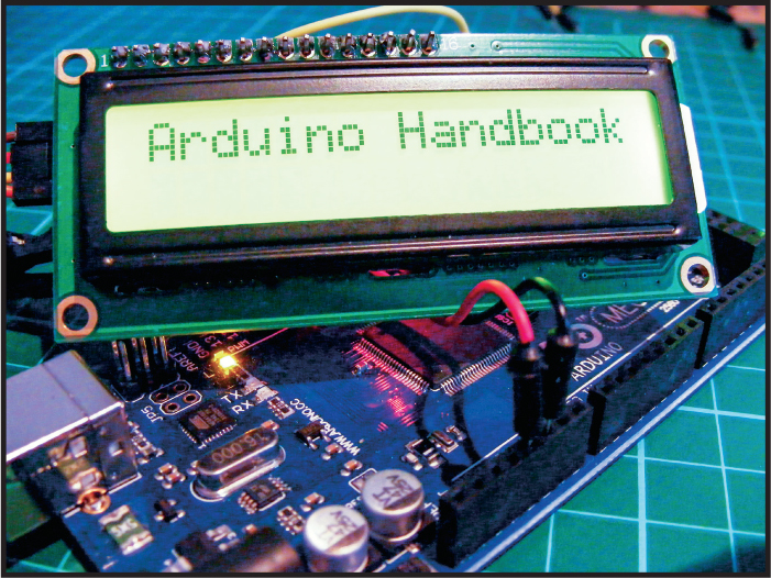
lcd.print("Arduino Handbook"); // Print a message to the LCD
}
void loop() { // Loop around again
}
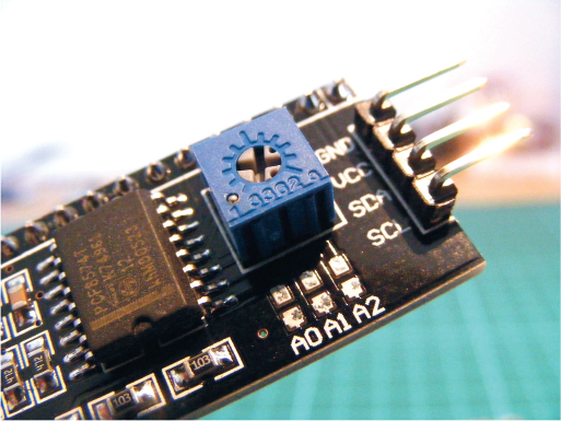
There is a potentiometer built into the module to control the contrast of the LCD screen, shown in Figure 16-6. Turn this carefully with a small screwdriver until the contrast on the screen looks right.
FIGURE 16-6: The small blue box on the back of the module is a potentiometer to control the contrast.
TROUBLESHOOTING
Q. The code compiles, but nothing shows on the screen.
• Double-check that the SDA and SCL pins are connected to the correct Arduino pins. If the LCD screen is lit but shows no characters, carefully turn the small potentiometer at the back of the module until the letters appear.
• If the screen still shows nothing and all the connections are correct, it may be that the solder on the header pins is not making a clean connection or you have soldered more than one pin together. Heat the area again with your soldering iron to melt the solder, and then use a solder sucker to remove any excess and resolder the header pins.