15
Bomb Decoder Game
In this project we’ll build a code-breaking bomb-decoding game. We’ll use an LCD screen and a keypad to give the players instructions and take input.

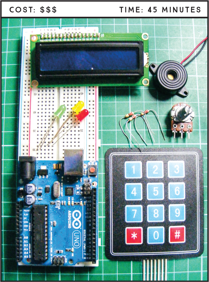
PARTS REQUIRED
Arduino board
Breadboard
Jumper wires
HD44780 16×2 LCD screen
10k-ohm potentiometer
Piezo sounder
3×4 membrane keypad
3 220-ohm resistors
Red LED
Yellow LED
Green LED
LIBRARIES REQUIRED
LiquidCrystal
Keypad
Tone
HOW IT WORKS
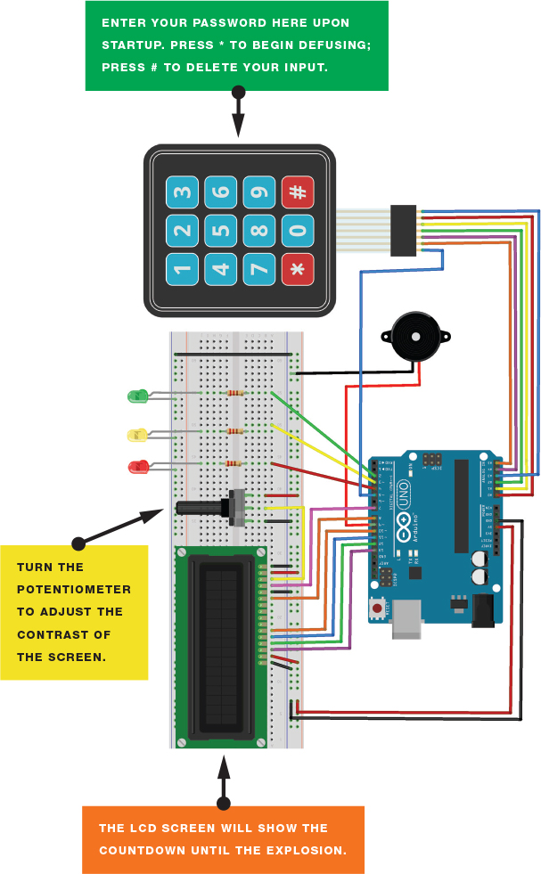
When you power up the Arduino, one player enters a four-digit code to start the bomb timer. They give the timer to another player, who presses the * button to begin decoding the bomb—this player (the “defuser”) must crack the code entered by the first player to defuse the bomb in time. If the defuser presses a wrong key, they can press # to delete their input and start again. If they enter the wrong code or the timer reaches zero, the bomb detonates and they lose.
During the game, the yellow LED flashes and the piezo sounder beeps in time to the countdown. The LCD screen displays the countdown and code input. When the bomb detonates, all the LEDs flash and the piezo sounds an explosion.
A good way to take this game further would be to ask the defuser four questions, each giving the defuser one digit of the bomb code. The defuser has a set time to answer the questions and input the four-digit code. Answer incorrectly or too late, and the bomb explodes!
THE BUILD
If required, prepare the LCD screen by soldering the header pins as described in “Preparing the LCD Screen” on page 109.
Place your LCD screen in the breadboard, inserting the header pins into the breadboard holes. Also place the potentiometer in the breadboard, and use the breadboard and jumper wires to connect your LCD screen, Arduino, and potentiometer as shown in the following table. There are multiple GND connections, so use the breadboard rail to make those connections to the Arduino GND pin.
LCD SCREEN
ARDUINO
1 VSS
GND
2 VDD
+5V
3 VO contrast
Potentiometer center pin
4 RS
Pin 7
5 R/W
GND
6 Enable
Pin 8
7 D0
No connection
8 D1
No connection
9 D2
No connection
10 D3
No connection
11 D4
Pin 10
12 D5
Pin 11
13 D6
Pin 12
14 D7
Pin 13
15 A BcL+
+5V
16 K BcL–
GND
You should have already connected the center pin of the 10k-ohm potentiometer to LCD pin 3 (VO). Now connect one of the outer pins to GND and the other to +5V, as shown in Figure 15-1. This controls the contrast of your LCD screen.
FIGURE 15-1: The potentiometer controls the contrast of your LCD screen.

Looking at the keypad head-on, as in Figure 15-2, the pins are numbered 1–7 from left to right. Connect the keypad pins as shown in the following table.
FIGURE 15-2: The 3×4 numeric keypad with seven pin connections

KEYPAD
ARDUINO
Pin 1
Pin 5
Pin 2
Pin A5
Pin 3
Pin A4
Pin 4
Pin A2
Pin 5
Pin A1
Pin 6
Pin A0
Pin 7
Pin A3
Connect the piezo sounder’s red wire directly to Arduino pin 9 and its black wire to Arduino GND.
PIEZO SOUNDER
ARDUINO
Red wire
Pin 9
Black wire
GND
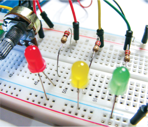
Place the green LED in the breadboard, connecting the short, negative leg to the negative breadboard rail via a 220-ohm resistor. Connect the green LED’s long, positive leg to pin 2. Do the same with the yellow LED to pin 3 and the red LED to pin 4, as shown in Figure 15-3 and the table that follows.
FIGURE 15-3: Connect the LEDs to the Arduino via a 220-ohm resistor.
LEDS
ARDUINO
Negative legs
GND
Green positive leg
Pin 2 via 220-ohm resistor
Yellow positive leg
Pin 3 via 220-ohm resistor
Red positive leg
Pin 4 via 220-ohm resistor
Connect the positive and negative breadboard power rails to +5V and GND, respectively.
Make sure your completed project circuit matches Figure 15-4, remember to add the required libraries to your Libraries folder, and then upload the code in “The Sketch” on page 127.
FIGURE 15-4: The circuit diagram for the bomb decoder game
PLAYING THE GAME
Figure 15-5 shows the different stages of playing the game.
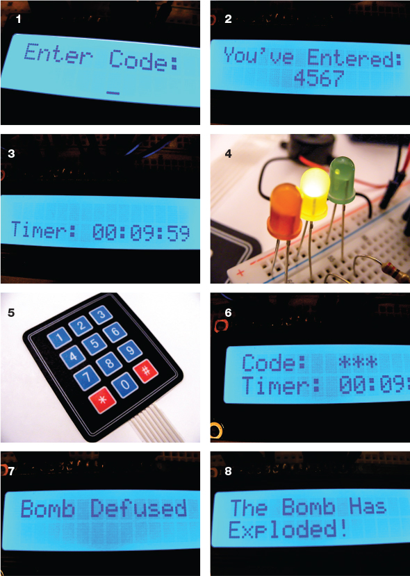
Enter the code to set up the bomb.
The bomb confirms the code entered.
The timer starts the countdown sequence.
The yellow LED flashes in time to the countdown.
Pass the keypad to another player (the defuser). They press the * button on the keypad, then enter the defuse code.
The screen does not show the numbers entered to defuse the bomb.
If the correct code is entered, the bomb is defused . . .
. . . but if not . . . Boom!
NOTE
All libraries and code can be downloaded from https://www.nostarch.com/arduinohandbook2/.
THE SKETCH
The sketch calls on the Keypad, LiquidCrystal, and Tone libraries. LiquidCrystal is included in your IDE, but you’ll have to download Keypad and Tone from the book’s resources at https://www.nostarch.com/arduinohandbook2/ and save them in your Libraries folder for the Arduino (see the primer for details on how to do that if you’re unsure).
First the sketch defines the timer duration, password length, LED pins, and keypad. It requests a code input from the first player by displaying “Enter Code:” and then stores that value as the bomb defusal code. When the second player (the defuser) presses *, the timer starts and waits for a code to be entered, and the yellow LED flashes in time to the countdown. If the code the defuser enters does not match the defusal code, the text “The Bomb Has Exploded!” displays on the screen and the LEDs and piezo indicate an explosion. If the defuser’s input is correct, the timer stops, the green LED lights, and the message “Bomb Defused” displays on the screen. The bomb will also explode if the timer reaches zero with no input. When the game ends, the code resets, ready for another game.
// Original code by Joey Meyer and Chase Cooley
// and used with kind permission
#include <Keypad.h>
#include <LiquidCrystal.h>
#include <Tone.h>
Tone tone1;
int Scount = 10; // Change this to the number of seconds to start from
int Mcount = 5; // Change this to the number of minutes to start from
int Hcount = 0; // Count hours
int DefuseTimer = 0; // Set timer to 0
long secMillis = 0; // Store last time for second add
long interval = 1000; // Interval for seconds
char password[4]; // Number of characters in password
int currentLength = 0; // Defines number currently writing
int i = 0;
char entered[4];
int ledPin = 4; // Red LED
int ledPin2 = 3; // Yellow LED
int ledPin3 = 2; // Green LED
// The pins we use on the LCD
LiquidCrystal lcd(7, 8, 10, 11, 12, 13);
const byte ROWS = 4; // Four rows
const byte COLS = 3; // Three columns
char keys[ROWS][COLS] = {
{'1', '2', '3'},
{'4', '5', '6'},
{'7', '8', '9'},
{'*', '0', '#'}
};
byte rowPins[ROWS] = {5, A5, A4, A2}; // Connect to the row pinouts
// of the keypad
byte colPins[COLS] = {A1, A0, A3}; // Connect to the column pinouts
// of the keypad
Keypad keypad = Keypad(makeKeymap(keys), rowPins, colPins, ROWS, COLS);
void setup() {
pinMode(ledPin, OUTPUT); // Sets the digital pin as output
pinMode(ledPin2, OUTPUT); // Sets the digital pin as output
pinMode(ledPin3, OUTPUT); // Sets the digital pin as output
tone1.begin(9);
lcd.begin(16, 2);
Serial.begin(9600);
lcd.clear();
lcd.setCursor(0,0);
lcd.print("Enter Code: ");
while (currentLength < 4) {
lcd.setCursor(currentLength + 6, 1);
lcd.cursor();
char key = keypad.getKey();
key == NO_KEY;
if (key != NO_KEY) {
if ((key != '*')&&(key != '#')) {
lcd.print(key);
password[currentLength] = key;
currentLength++;
tone1.play(NOTE_C6, 200);
}
}
}
if (currentLength == 4) {
delay(500);
lcd.noCursor();
lcd.clear();
lcd.home();
lcd.print("You've Entered: ");
lcd.setCursor(6, 1);
lcd.print(password[0]);
lcd.print(password[1]);
lcd.print(password[2]);
lcd.print(password[3]);
tone1.play(NOTE_E6, 200);
delay(3000);
lcd.clear();
currentLength = 0;
}
}
void loop() {
timer();
char key2 = keypad.getKey(); // Get the key
if (key2 == '*') {
lcd.clear();
lcd.setCursor(0, 0);
lcd.print("Code: ");
while (currentLength < 4) {
timer();
char key2 = keypad.getKey();
if (key2 == '#') {
currentLength = 0;
lcd.clear();
lcd.setCursor(0, 0);
lcd.print("Code: ");
}
else if (key2 != NO_KEY) {
lcd.setCursor(currentLength + 7, 0);
lcd.cursor();
lcd.print(key2);
entered[currentLength] = key2;
currentLength++;
tone1.play(NOTE_C6, 200);
delay(100);
lcd.noCursor();
lcd.setCursor(currentLength + 6, 0);
lcd.print("*");
lcd.setCursor(currentLength + 7, 0);
lcd.cursor();
}
}
if (currentLength == 4) {
if (entered[0] == password[0] && entered[1] == password[1] && entered[2] == password[2] &&entered[3] == password[3]) {
lcd.noCursor();
lcd.clear();
lcd.home();
lcd.print("Bomb Defused");
currentLength = 0;
digitalWrite(ledPin3, HIGH);
delay(2500);
lcd.setCursor(0, 1);
lcd.print("Reset the Bomb");
delay(1000000);
}
else {
lcd.noCursor();
lcd.clear();
lcd.home();
lcd.print("Wrong Password!");
if (Hcount > 0) {
Hcount = Hcount - 1;
}
if (Mcount > 0) {
Mcount = Mcount - 59;
}
if (Scount > 0) {
Scount = Scount - 59;
}
delay(1500);
currentLength = 0;
}
}
}
}
void timer() {
Serial.print(Scount);
Serial.println();
if (Hcount <= 0) { // If timer reaches 0, LCD displays explosion
if ( Mcount < 0 ) {
lcd.noCursor();
lcd.clear();
lcd.home();
lcd.print("The Bomb Has ");
lcd.setCursor(0, 1);
lcd.print("Exploded!");
while (Mcount < 0) {
digitalWrite(ledPin, HIGH); // Sets the LED on
tone1.play(NOTE_A2, 90);
delay(100);
digitalWrite(ledPin, LOW); // Sets the LED off
tone1.play(NOTE_A2, 90);
delay(100);
digitalWrite(ledPin2, HIGH); // Sets the LED on
tone1.play(NOTE_A2, 90);
delay(100);
digitalWrite(ledPin2, LOW); // Sets the LED off
tone1.play(NOTE_A2, 90);
delay(100);
digitalWrite(ledPin3, HIGH); // Sets the LED on
tone1.play(NOTE_A2, 90);
delay(100);
digitalWrite(ledPin3, LOW); // Sets the LED off
tone1.play(NOTE_A2, 90);
delay(100);
}
}
}
lcd.setCursor(0, 1); // Sets cursor to 2nd line
lcd.print("Timer:");
if (Hcount >= 10) {
lcd.setCursor(7, 1);
lcd.print(Hcount);
}
if (Hcount < 10) {
lcd.setCursor(7, 1);
lcd.write("0");
lcd.setCursor(8, 1);
lcd.print(Hcount);
}
lcd.print(":");
if (Mcount >= 10) {
lcd.setCursor(10, 1);
lcd.print(Mcount);
}
if (Mcount < 10) {
lcd.setCursor(10, 1);
lcd.write("0");
lcd.setCursor(11, 1);
lcd.print(Mcount);
}
lcd.print (":");
if (Scount >= 10) {
lcd.setCursor(13, 1);
lcd.print(Scount);
}
if (Scount < 10) {
lcd.setCursor(13, 1);
lcd.write("0");
lcd.setCursor(14, 1);
lcd.print(Scount);
}
if (Hcount < 0) {
Hcount = 0;
}
if (Mcount < 0) {
Hcount --;
Mcount = 59;
}
if (Scount < 1) { // If 60 do this operation
Mcount --; // Add 1 to Mcount
Scount = 59; // Reset Scount
}
if (Scount > 0) { // Do this operation 59 times
unsigned long currentMillis = millis();
if (currentMillis - secMillis > interval) {
tone1.play(NOTE_G5, 200);
secMillis = currentMillis;
Scount --; // Add 1 to Scount
digitalWrite(ledPin2, HIGH); // Sets the LED on
delay(10); // Waits for a second
digitalWrite(ledPin2, LOW); // Sets the LED off
delay(10); // Waits for a second
}
}
}
TROUBLESHOOTING
Q. Nothing is displayed on the LCD screen.
• Make sure you’ve connected power to the breadboard rails and the connections match the tables in this chapter.
• Turn the potentiometer to change the contrast of the screen until you see text.
• If the screen has garbled messages on it, you haven’t wired it up correctly; recheck your wiring against the circuit diagram in Figure 15-4.
Q. The LEDs do not light when expected.
• Check your wiring against the circuit diagram in Figure 15-4 and ensure that the short leg of the LED is connected to the ground rail of the breadboard.
• It’s easy to forget to add power to the breadboard rails, so make sure you connect the ground and power rails on either side of the breadboard to the Arduino with a jumper wire.
• Check that your LEDs and resistors are firmly inserted into the breadboard and they line up with one another.
• If the wrong LED lights up, you’ve probably connected to the wrong pin numbers by mistake, so just change them around.
Q. The piezo sounder does not make a noise.
• The positive red wire of the sounder should be connected to pin 9 and the black ground wire to GND. If the sounder does still not make a noise, try replacing it with another one.
Q. When the keypad is pressed, the numbers are incorrect or do not register.
• Make sure the connections of the keypad to the Arduino match the circuit diagram in Figure 15-4 exactly.
• The configuration is set up specifically for this project’s 3×4 numeric keypad, so if your keypad is different, check the data sheet to find out which pins you need to connect.