
24
Voice-Controlled LED
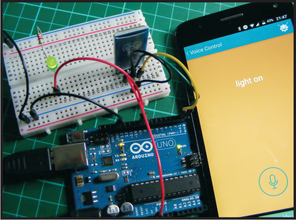
In this project we’ll use a bluetooth module, a smartphone, and a voice recognition app to control an LED with vocal commands.
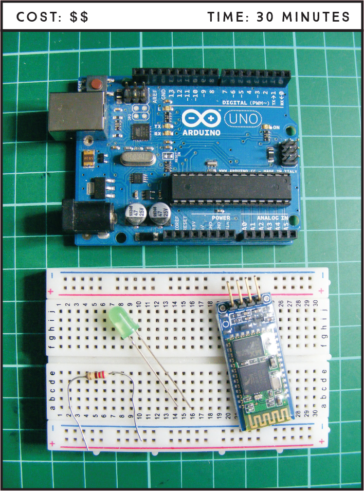
PARTS REQUIRED
Arduino board
Breadboard
Jumper wires
HC-06 Bluetooth module
LED
220-ohm resistor
Android smartphone
HOW IT WORKS
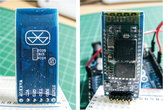
Bluetooth wireless technology uses radio waves to transmit and exchange data over short distances. Smartphones, laptops, and multimedia devices such as speakers use Bluetooth as a common standard. We’ll use the inexpensive HC-06 Bluetooth module (Figure 24-1) to pair (connect) our Arduino to a smartphone so we can turn an LED on and off remotely using a voice recognition app. This module has six pins, but we’ll just use the middle four. The pins should be labeled on the front.
FIGURE 24-1: The HC-06 Bluetooth module
The app we’ll use is Arduino Bluetooth Control from BroxCode, available to download for free on the Google Play store for Android devices. There are many other similar free apps available for both Android and Apple devices and the principles of use should be the same for each, but the BroxCode app has some additional features that we’re using in this project, such as voice recognition through Google Assistant.
THE BUILD
Before you build the Bluetooth controller, you need to upload the code to the Arduino. This is because the serial communication from your PC to the Arduino uses the same pins that we’ll be connecting to the Bluetooth module.
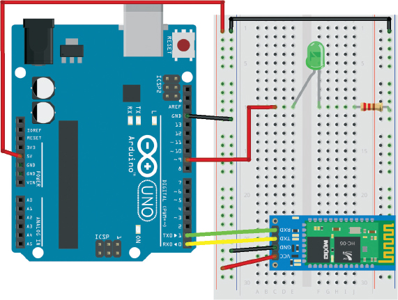
Upload the code in “The Sketch” on page 220, and then insert the Bluetooth module into the breadboard and connect VCC to the positive power rail of the breadboard, GND to the GND power rail, TXD to Arduino pin 0 (RX), and RXD to Arduino pin 1 (TX), as shown in the following table.
HC-06 BLUETOOTH MODULE
ARDUINO
VCC
+5V
GND
GND
TXD
Pin 0 (RX)
RXD
Pin 1 (TX)
Insert the LED into the breadboard with the legs straddling the center break. Use a 220-ohm resistor to connect the shorter, negative leg of the LED to the GND rail of the breadboard. Connect the longer, positive leg of the LED to pin 9 of the Arduino using a jumper wire, as outlined in the following table.
LED
ARDUINO
Positive leg
Pin 9
Negative leg
GND
Connect the GND rail of the breadboard to Arduino GND and the positive rail to Arduino +5V.
Check that your build matches the diagram in Figure 24-2.
FIGURE 24-2: The circuit diagram for the Bluetooth voice-controlled LED
ARDUINO BLUETOOTH CONTROL
The Arduino Bluetooth Control app offers six control options, all of which send data to the Arduino via different methods (Figure 24-3). You can customize each to your own preferences.
FIGURE 24-3: The menu screen on the Arduino Bluetooth Control app

• Arrow Keys: Here you’ll find customizable arrow buttons.
• Terminal: This is a classic terminal for sending and receiving data, displayed with a timestamp corresponding to each action.
• Accelerometer: This tool reads movement using the gesture sensor of your phone.
• Buttons and Slider: Here you’ll find six fully customizable buttons and a slider view that shows up when you rotate your device. You can set the range of the data for this slider.
• Metrics: This tool is optimized to receive data via the println() function of the Arduino, which allows your paired phone to receive notifications by SMS from another phone. You only need to specify the number in the Settings section. This function is explained further shortly.
• Voice Control: This great tool uses the Google voice command on your Android device to let you customize your own vocal commands and use them to control the Arduino.
Now you need to download the Arduino Bluetooth Control app from the Google Play app store and set it up.
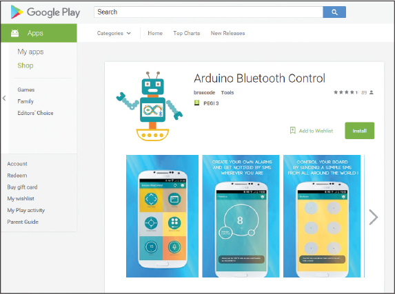
Go to https://play.google.com/store/ and search for “Arduino Bluetooth Control.” You’ll probably get several apps in your results, but the one you want is precisely named “Arduino Bluetooth Control,” as shown in Figure 24-4. Click Install to download it to your device. The app is free but does include some ads.
FIGURE 24-4: Arduino Bluetooth Control from BroxCode on Google Play
Once you’ve downloaded the app, power your Arduino to start the Bluetooth module. Go to your Bluetooth settings on your smartphone, turn on Bluetooth, and select MORE SETTINGS to view visible devices. You should see the HC-06 module as an available device. Select it to pair with your phone. You’ll be asked for a password to connect: the default for the module is 1234 or in some instances 0000, so try both if the first doesn’t work.
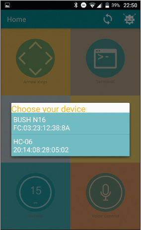
When your device is paired, open the Arduino Bluetooth Control app. From the window that appears showing all available devices, select the HC-06 module, as shown in Figure 24-5. You won’t need to choose the device every time you power up—the app will remember it.
FIGURE 24-5: Pairing your device
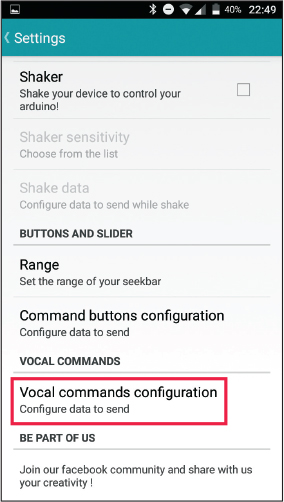
You’re going to use the Voice Control function to turn the LED off and on when you speak certain commands into the smartphone. Select the Voice Control function, and you’ll be taken to the Settings menu, shown in Figure 24-6. Choose Vocal commands configuration. We’ll use this to define our input and output functions.
FIGURE 24-6: Selecting the Vocal commands configuration setting
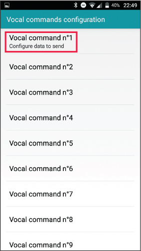
Select Vocal command n°1, as shown in Figure 24-7.
FIGURE 24-7: Setting your first voice command
Here you give the input that will trigger the first function. Enter light on as text, as shown in the screen on the left in Figure 24-8. The app will then ask for the output data to send to the Arduino when you give the input command. On this screen, enter 1 for on or HIGH, as we’ve seen in previous LED projects (shown in the screen on the right in Figure 24-8). When the app hears the vocal command “light on” through the phone, the number 1 will be sent to the Arduino as an input, and power will be sent to the LED to light it up.
Carry out the same steps to define Vocal command n°2 with the input light off and the output data 0, as shown in Figure 24-9. This command will switch the LED off.
Now you’ve configured your commands so that when you press the voice command function and tap the microphone button on the screen, the app will listen for your command and, depending on the input, switch the LED on or off.
FIGURE 24-8: Configuring our LED to turn on with the voice command “light on”

FIGURE 24-9: Configuring the “light off” function

The app also has a function to let you control the Arduino using SMS. Once the app is launched and connected to the Arduino, you can send data to the Arduino by sending an SMS text to the phone paired with the Bluetooth module, as long as the paired phone is in range of the module. Simply text Arduino 1 to the phone connected to the Arduino, and that phone will send 1 to the module to light your LED. Text Arduino 0, and a 0 will be sent to switch your LED off. This way you can have control through Bluetooth from anywhere in the world!
THE SKETCH
The sketch for this project is quite simple. It starts by creating a variable to hold the data from the Bluetooth module. It sets the data rate for serial communication to 9600 and sets pin 9 as an output for our LED. In the loop, it checks for data to be sent to the Arduino from the Bluetooth module. The loop reads the data, and also sends it to the Serial Monitor so we can check that it’s working correctly. If the Arduino receives a 1 from the app, pin 9 will be set to HIGH, which will turn on the LED. If the Arduino receives a 0, pin 9 is set as LOW and the LED is turned off.
Using these principles, you could add numerous relays in place of the LED and begin to automate your home from anywhere. You could set it up to turn on your living room lights before you enter your house, set the thermostat when you’re on your way home, or have your favorite music already playing as you walk in the door.
char data = 0; // Create a variable for data
void setup() {
Serial.begin(9600); // Data rate for serial communication
pinMode(9, OUTPUT); // Set pin 9 as an output
}
void loop() {
if (Serial.available() > 0) { // Send data
data = Serial.read(); // Read incoming data and
// store it into variable data
Serial.print(data); // Print data value to the Serial Monitor
Serial.print("
"); // Start a new line
if (data == '1') // If value is 1, turn on LED
digitalWrite(9, HIGH);
else if (data == '0') // If value is 0, turn off LED
digitalWrite(9, LOW);
}
}
TROUBLESHOOTING
Q. The code compiles, but the LED does not light.
• Make sure you’ve connected the GND and power pins from the Arduino to the correct breadboard power rails and that the Arduino has power connected.
• Check that the LED is inserted the correct way, with the longer leg connected to the positive power and the shorter leg to GND. Check that the resistors are inserted fully and line up with the corresponding LED leg.
• With the project powered and connected to your PC, open the Arduino IDE Serial Monitor to see if the Arduino is receiving data from the app. If you don’t see data streaming in the Serial Monitor, double-check that the TXD of the module is connected to RX of the Arduino and the RXD of the module to Arduino TX.
• If the app does not work when opened on your smartphone, check the compatibility of your phone with the app on the developer’s site. You may need to use an alternative app.
• The data set in your app must match the data expected in the sketch, so make sure you’ve used 1 for on and 0 for off.