
9
Audio LED Visualizer
In this project we’ll use a sound sensor that will light a series of LEDs depending on the beat and volume of the sound it detects.
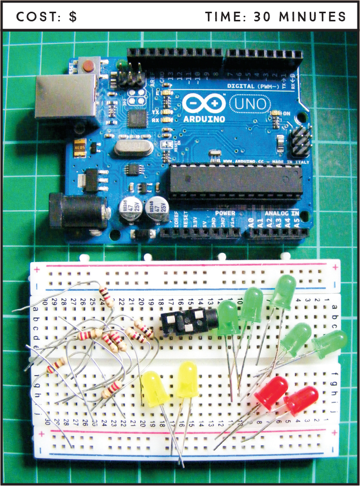
PARTS REQUIRED
Arduino board
Breadboard
Solid-core wires with ends stripped
Jumper wires
2 red LEDs
2 yellow LEDs
5 green LEDs
9 220-ohm resistors
3.5 mm female headphone jack
HOW IT WORKS
In Project 2 we created an LED night-light that was controlled by a light sensor. This project is similar, but the LEDs will be controlled by sound. We’ll connect a headphone jack to the Arduino, hook the jack up to an MP3 player, and watch the lights “dance” to the music. The signal from the MP3 player is picked up by the headphone jack and received as pulses by the Arduino A0 pin. The pattern of the pulses depends on the beat and volume of the music. The Arduino then sends power to the LEDs in direct response to the pattern of the music. As an alternative to using the MP3 player, you could add a microphone and have your own voice visualized in colored lights.
THE BUILD
Place the LEDs into the breadboard with the short, negative legs in the GND rail. Connect the GND rail on the breadboard to Arduino GND.
Insert a 220-ohm resistor for each LED, making sure the resistors straddle the center break, and connect one leg to each positive LED leg (see Figure 9-1). Connect the other leg of each resistor to Arduino digital pins 2 through 10 with jumper wires, as shown in the following table.
LED
ARDUINO
Positive leg
Digital pins 2–10 (via resistor)
Negative leg
GND
FIGURE 9-1: A resistor is required between the LEDs and power.

NOTE
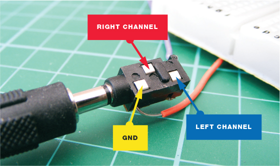
This headphone jack was reclaimed from a radio bought in a dollar store, but if you can find one to purchase, that will work too. On the headphone jack, the pins are GND, right channel, and left channel.
Connect the ground pin of the headphone jack directly to GND, and the left channel of the jack to Arduino pin A0, as outlined in the following table. You could use jumper wire for this, but I’ve used solid-core wire and stripped the ends for connections. Stranded wire is too thin and won’t connect easily to the Arduino pins. (See Figure 9-2 for the positions of the jack pins.)
HEADPHONE JACK
ARDUINO
Ground
GND
Left channel
A0
FIGURE 9-2: 3.5 mm headphone jack with MP3 player jack plugged in
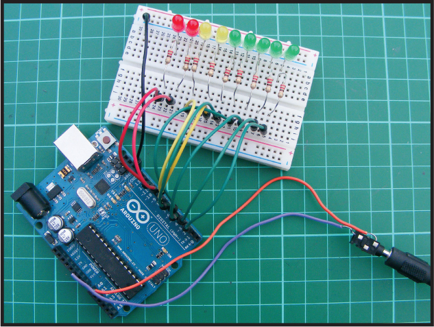
Check your setup against the circuit diagram in Figure 9-3, and then upload the code in “The Sketch” on page 81.
FIGURE 9-3: The circuit diagram for the audio LED visualizer

Plug your MP3 player into the headphone jack for audio input. The LEDs will dance to the beat and volume of your music!
THE SKETCH
The sketch first sets the Arduino pins connected to the LEDs, pins 2–10, as outputs. The input in this sketch is the signal from the MP3 player, received through the headphone jack, which is read by analog pin A0. The music sent by the player is picked up as a series of pulses by A0, and the volume and beat of the music determine how the LEDs light up. The louder the music, the more LEDs will light; and the faster the music’s beat, the faster the LEDs will flash.
// Used with kind permission from James Newbould
int led[9] = {2, 3, 4, 5, 6, 7, 8, 9, 10}; // Pins connected to LEDs
int leftChannel = A0; // Pin connected to headphone jack
int left, i; // Create a variable for left and i
void setup() {
for (i = 0; i < 9; i++)
pinMode(led[i], OUTPUT); // Set LEDs as output
}
void loop() { // Light LEDs from left to right and back again
// depending on the value from A0
left = analogRead(leftChannel); // Read left value
left = left / 10; // Set level of sensitivity between 1 and 50
if (left == 0) {
for (i = 0; i < 9; i++) { // If value is low, turn off LED
digitalWrite(led[i], LOW);
}
}
else { // Or else turn on LEDs in sequence
for (i = 0; i < left; i++) {
digitalWrite(led[i], HIGH);
}
for (i = i; i < 9; i++) {
digitalWrite(led[i], LOW);
}
}
}
TROUBLESHOOTING
Q. The code compiles, but some or all of the LEDs do not light up as expected.
• If none of the LEDs light, make sure you’ve connected the GND wire from the Arduino to the correct breadboard power rail and that the Arduino has power connected.
• If only some LEDs light, check that the LEDs are inserted the correct way, with the longer leg connected to the positive power and the short leg to GND. LEDs have polarity, so they must be connected correctly. Check that each resistor is inserted fully and lines up in the same row as the corresponding LED leg.
• Make sure the LEDs are connected to the Arduino pins defined in the sketch and match the circuit diagram in Figure 9-3; the first part of the sketch defines pins 2–10 as outputs, so these should be used.
• If an LED still fails to light, it may be burned out or faulty. An easy way to check is to swap the LED with another in the sequence and see if that solves the issue. If you find that the LED works in another position, it means the resistor is either faulty or not inserted fully. Depending on the outcome, replace the LED or resistor with a functioning component.