7
NeoPixel Compass
In this chapter we’ll use a three-axis sensor and an RGB LED ring to create a compass that indicates north by lighting the LEDs in that direction.

PARTS REQUIRED
Arduino board
Jumper wires
HMC5883L three-axis sensor
Adafruit NeoPixel ring with 16 RGB LEDs
9V battery pack with 6 AA batteries
LIBRARIES REQUIRED
Wire
FastLED
HMC5883L
HOW IT WORKS
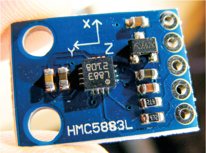
The HMC5883L three-axis sensor (Figure 7-1) is a multichip module that senses magnetic force. The module measures both the direction and the magnitude of Earth’s magnetic fields. We will use the HMC5883L library to turn our project into an electronic compass.
FIGURE 7-1: The HMC5883L three-axis module runs on 3.3V rather than 5V.
Earth’s magnetic field is believed to be generated by electric currents in the conductive material of its core that are created by heat escaping. Since Earth is effectively a magnet, the north end of a compass magnet is drawn to align with its magnetic field.
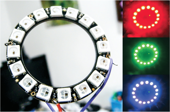
To visualize our compass direction we will use the Adafruit NeoPixel ring, shown in Figure 7-2. The NeoPixel ring is made up of 16 RGB LEDs, each of which has its own driver chip and so can be controlled individually. A single data line controls the LEDs, and we’ll use the FastLED library to control the colors.
FIGURE 7-2: The Adafruit 16 RGB NeoPixel ring
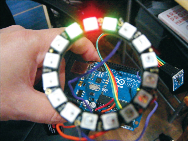
When the project is powered up, the HMC5883L module will detect magnetic north and display it on the NeoPixel ring by lighting the LEDs in that direction. If you turn around while holding the powered NeoPixel compass, the LED lights will move to always point north.
THE BUILD
NOTE
The pin labeled DRDY on the compass module is not used in this project.
Your HMC5883L module may arrive with the header pins loose, so the first step is to solder the header pins into the module. You will need the strip of five header pins that should come with the module. Insert the header pins into the five available holes on the module and solder each pin for a couple of seconds (check the “Quick Soldering Guide” on page 12 if you need help). The module communicates with the Arduino using I2C and the Wire library.
In order to use the compass properly you need to calibrate the HMC5883L module. Connect the module to the Arduino as shown in the following table.
HMC5883L MODULE
ARDUINO
VCC
+3.3V
GND
GND
SCL
Pin A5 (SLC)
SDA
Pin A4 (SDA)
Download the HMC5883L library and add it to the Arduino library folder on your PC. Check the library section in the primer if you need a reminder of how to do this. Once you have the library saved, restart your Arduino IDE. When it opens again, it should have the library saved in Examples. Select File ▸ Examples ▸ Arduino-HMC5883L-Master ▸ HMC5883L_calibrate. If you can’t see the sketch, make sure you’ve saved the library in your Arduino library folder. The following sketch will be shown in the IDE main window:
/*
Calibrate HMC5883L. Output for HMC5883L_calibrate_processing.pde
Read more: http://www.jarzebski.pl/arduino/czujniki-i-sensory/3-osiowy-magnetometr-hmc5883l.html
GIT: https://github.com/jarzebski/Arduino-HMC5883L
Web: http://www.jarzebski.pl
(c) 2014 by Korneliusz Jarzebski
*/
#include <Wire.h>
#include <HMC5883L.h>
HMC5883L compass;
int minX = 0;
int maxX = 0;
int minY = 0;
int maxY = 0;
int offX = 0;
int offY = 0;
void setup() {
Serial.begin(9600);
// Initialize Initialize HMC5883L
while (!compass.begin()) {
delay(500);
}
// Set measurement range
compass.setRange(HMC5883L_RANGE_1_3GA);
// Set measurement mode
compass.setMeasurementMode(HMC5883L_CONTINOUS);
// Set data rate
compass.setDataRate(HMC5883L_DATARATE_30HZ);
// Set number of samples averaged
compass.setSamples(HMC5883L_SAMPLES_8);
}
void loop() {
Vector mag = compass.readRaw();
// Determine Min / Max values
if (mag.XAxis < minX) minX = mag.XAxis;
if (mag.XAxis > maxX) maxX = mag.XAxis;
if (mag.YAxis < minY) minY = mag.YAxis;
if (mag.YAxis > maxY) maxY = mag.YAxis;
// Calculate offsets
offX = (maxX + minX)/2;
offY = (maxY + minY)/2;
/*Serial.print(mag.XAxis);
Serial.print(":");
Serial.print(mag.YAxis);
Serial.print(":");
Serial.print(minX);
Serial.print(":");
Serial.print(maxX);
Serial.print(":");
Serial.print(minY);
Serial.print(":");
Serial.print(maxY);
Serial.print(":"); */
Serial.print(offX);
Serial.print(":");
Serial.print(offY);
Serial.print(" ");
}We only need the X and Y Serial.print lines in this last bunch of Serial.print commands, so comment out the Serial.print lines of the sketch shown in bold. Upload the sketch to the Arduino and open the Serial Monitor. A series of numbers will display, as shown in Figure 7-3.
FIGURE 7-3: The calibration numbers will be shown in the IDE Serial Monitor window.

Rotate the sensor 360 degrees while it’s connected to the Arduino IDE Serial Monitor, and you should see two digits displayed; in Figure 7-3, they’re 13 and –294. You’ll need these calibration numbers in the sketch later, so make a note of them.
You can improve the accuracy of your compass by finding the magnetic declination for your location. The magnetic declination, or variation, is the angle on the horizontal plane between magnetic north (where a compass points) and true north (the direction toward the geographic North Pole). You can find your magnetic declination by visiting http://www.magnetic-declination.com/ and entering your location in the search bar at the top left. Your result will appear as shown in Figure 7-4.
FIGURE 7-4: The magnetic declination for your location can be found at http://www.magnetic-declination.com/.
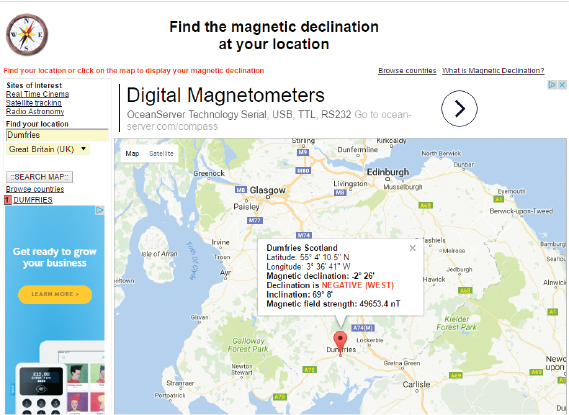
The values you need are the magnetic declination and the declination; in Figure 7-4, they’re –2° 26' and NEGATIVE (WEST), respectively, but yours will be different. Record these values too, as we’ll use them in the sketch at the end of the project—with one minor change. For example, my values were –2 and 26. We don’t put the negative (minus) sign before the first value but instead put it after, like so:
float declinationAngle = (2 - (26.0 / 60.0)) / (180 / M_PI);
If your location’s declination were POSITIVE (WEST), then you would add the positive (plus) sign instead:
float declinationAngle = (2 + (26.0 / 60.0)) / (180 / M_PI);
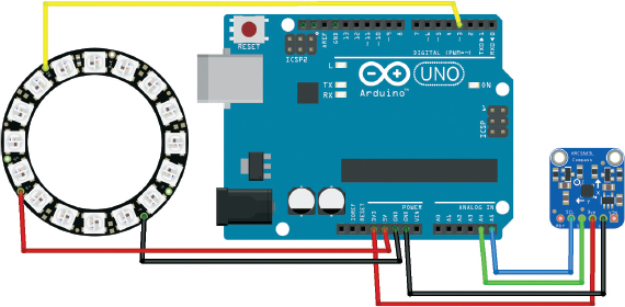
Next, add the NeoPixel ring to the Arduino by connecting V on the NeoPixel to +5V on the Arduino, GND to GND, and In on the NeoPixel to pin 3 on the Arduino.
NEOPIXEL
ARDUINO
V
+5V
GND
GND
In
Pin 3
Check your setup against the circuit diagram in Figure 7-5, and then upload the code in “The Sketch” below.
FIGURE 7-5: The circuit diagram for the NeoPixel compass
THE SKETCH
First we call on the Wire, FastLED, and HMC5883L libraries. The Wire library is installed with the Arduino IDE, but you need to add the others. Download them in the book’s resources at http://www.nostarch.com/arduinohandbook2/, and follow the guide in the primer for more information on adding libraries.
Next we declare the number of LEDs on the NeoPixel ring (16) and assign pin 3 on the Arduino to control it. We then call on a number of settings in the HMC5883L library to control the compass module. At ➊ we add the compass offset values for X and Y, which should match your calibration from Step 4 earlier; mine were 13, –294, respectively. At ➋ we add the magnetic declination from Step 6. Again, remember to change it to the one for your location.
The next set of calculations allows the sensor to map to a 360-degree rotation. Then we set the LEDs on the NeoPixel to move depending on the readings of the sensor to point north. Three LEDs are lit: one red LED that points north and a green LED on either side of it. The compass is best used outdoors with the module, away from any strong electrical or magnetic sources, and should be powered from a battery pack rather than a USB connection.
// Code by brainy-bits.com and used with kind permission
// https://brainy-bits.com/tutorials/find-your-way-using-the-hmc5883l/
#include <Wire.h>
#include "FastLED.h"
#include <HMC5883L.h>
#define NUM_LEDS 16 // Number of LEDs on Ring
#define DATA_PIN_RING 3 // Pin 3 connected to RGB Ring
CRGB leds_RING[NUM_LEDS];
HMC5883L compass;
int fixedHeadingDegrees; // Used to store Heading value
void setup() {
Serial.begin(9600);
Wire.begin(); //Setup I2C
// Set up the FastLED library with the neopixel ring data
FastLED.addLeds<NEOPIXEL,DATA_PIN_RING>(leds_RING, NUM_LEDS);
// Set measurement range
compass.setRange(HMC5883L_RANGE_1_3GA);
// Set measurement mode
compass.setMeasurementMode(HMC5883L_CONTINOUS);
// Set data rate
compass.setDataRate(HMC5883L_DATARATE_30HZ);
// Set number of samples averaged
compass.setSamples(HMC5883L_SAMPLES_8);
// Set calibration offset. See HMC5883L_calibration.ino
➊ compass.setOffset(13, -224);
}
void loop() {
Vector norm = compass.readNormalize();
// Calculate heading
float heading = atan2(norm.YAxis, norm.XAxis);
// Set declination angle on your location and fix heading
// Find your declination on http://magnetic-declination.com/
// (+) Positive or (-) for negative
// For Dumfries, Scotland declination angle is -2 '26W (negative)
// Formula: (deg + (min / 60.0)) / (180 / M_PI);
float declinationAngle = (2.0 – (26.0 / 60.0)) / (180 / M_PI);
➋ heading -= declinationAngle;
// Correct for heading < 0deg and heading > 360deg
if (heading < 0) {
heading += 2 * PI;
}
if (heading > 2 * PI) {
heading -= 2 * PI;
}
// Convert to degrees
float headingDegrees = heading * 180 / M_PI;
// To fix rotation speed of HMC5883L compass module
if (headingDegrees >= 1 && headingDegrees < 240) {
fixedHeadingDegrees = map(headingDegrees * 100, 0, 239 * 100, 0, 179 * 100) / 100.00;
}
else {
if (headingDegrees >= 240) {
fixedHeadingDegrees = map(headingDegrees*100, 240*100, 360*100, 180*100, 360*100) / 100.00;
}
}
int headvalue = fixedHeadingDegrees / 18;
int ledtoheading = map(headvalue, 0, 15, 15, 0);
// Clear the ring
FastLED.clear();
// New heading
if (ledtoheading == 0) {
leds_RING[15] = CRGB::Red;
leds_RING[0] = CRGB::Green;
leds_RING[14] = CRGB::Green;
}
else {
if (ledtoheading == 15) {
leds_RING[0] = CRGB::Red;
leds_RING[15] = CRGB::Green;
leds_RING[1] = CRGB::Green;
}
else {
leds_RING[ledtoheading] = CRGB::Red;
leds_RING[ledtoheading+1] = CRGB::Green;
leds_RING[ledtoheading-1] = CRGB::Green;
}
}
FastLED.setBrightness(50);
FastLED.show();
delay(100);
}
TROUBLESHOOTING
Q. The code compiles, but the RGB LEDs do not light up as expected.
• If no LEDs are lit, double-check your wiring, particularly that the data pin of the NeoPixel is connected to pin 3 on the Arduino.
• Check that your power for the NeoPixel is connected to GND and +5V. The compass module should be connected to GND and +3.3V. The Arduino should be powered by your battery pack, not the USB cable from your PC.
• Make sure you have calibrated the module and entered the values using the steps shown earlier. The compass module should be held horizontally and in line with the RGB ring. The ring and the module should always be moved together.
• The module is best used outdoors, as it is very sensitive to metal and electrical interference.
• Try to keep the power for your Arduino and the sensor as far apart as possible to avoid interference.