
3
Seven-Segment LED Count Down Timer
In this project we’ll create a simple timer that counts down from 9 to 0. This can be used in any number of useful projects!
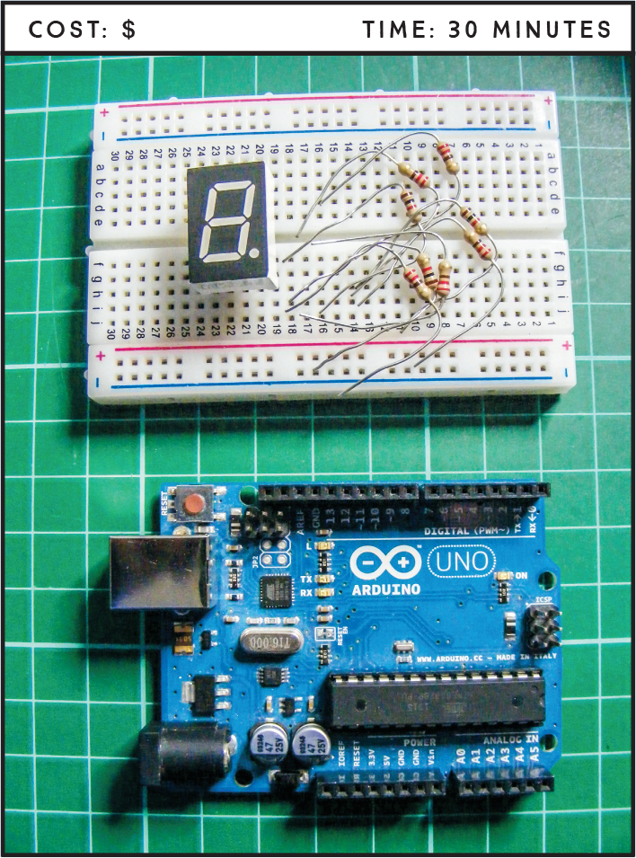
PARTS REQUIRED
Arduino board
Breadboard
Jumper wires
Seven-segment, single-digit common-cathode LED
8 220-ohm resistors
HOW IT WORKS
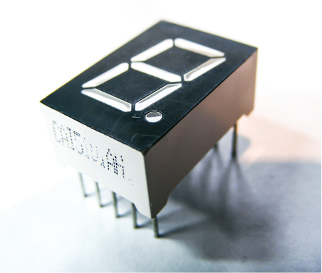
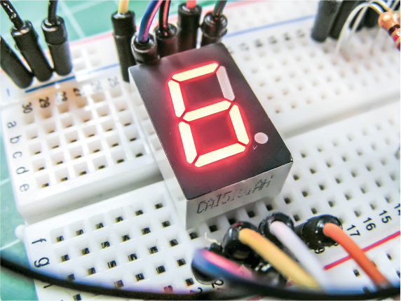
A seven-segment LED display shows a single digit or character using LED segments. Each segment is an individual LED, and by controlling which segments are lit at any time, we can display numeric values. We’re using a single-digit display in this project, shown in Figure 3-1, but there are also two-, three-, four-, and eight-digit variations available.
FIGURE 3-1: A seven-segment LED
NOTE
The cathode of a device is the negative connection, usually indicated with a minus sign (–) and sometimes referred to as ground (abbreviated GND). It is connected to negative power. The anode of a device is the positive connection, usually indicated with a plus sign (+) and connected to positive power.
This project will create a simple timer to count down from 9 to 0. The seven-segment LED has 10 pins. Seven pins control the seven LEDs that light up to form each digit, and the eighth pin controls the decimal point. The other two pins are the common-cathode (–) or common-anode (+) pins, which add power to the project. Our seven-segment LED is common cathode, meaning one side of each LED needs to connect to ground. It’s important to note that the code will work only with a common-cathode LED. If you have a common-anode LED you want to use, check the troubleshooting section at the end of this chapter before uploading the sketch. Each LED segment requires a resistor to limit the current; otherwise, it will burn out.
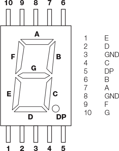
The pins are labeled with a letter, as shown in Figure 3-2. The numbered pins control the segments as shown on the right. The Arduino creates the number by turning the LEDs off or on in different combinations.
FIGURE 3-2: A typical pin layout for a seven-segment LED
THE BUILD
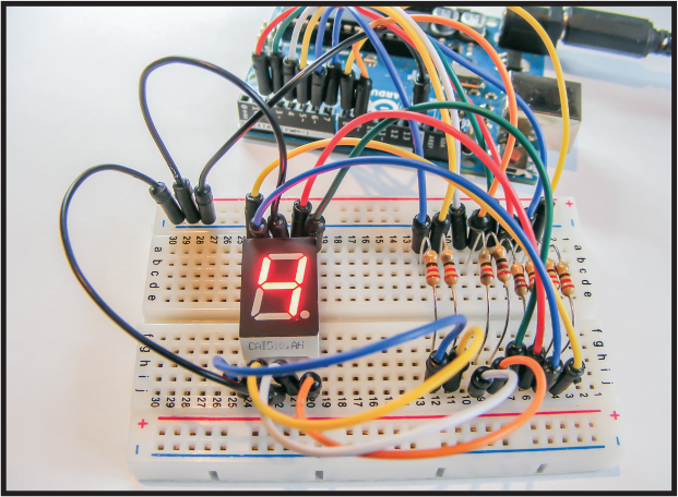
Place the seven-segment display in a breadboard as shown in Figure 3-3, making sure the pins straddle either side of the center break. Connect LED pins 3 and 8 to the GND rail.
FIGURE 3-3: The seven-segment LED pins should straddle the center break of the breadboard.
Connect LED pins 1, 2, 4, 5, 6, 7, and 9 as shown in the following table, remembering to insert a 220-ohm resistor between the LED and the Arduino connection. It’s important that the resistors straddle the center break on the breadboard, as shown in the circuit diagram in Figure 3-4.
ARDUINO
SEVEN-SEGMENT LED SECTION
SEVEN-SEGMENT LED DISPLAY
Pin 2
A
Pin 7
Pin 3
B
Pin 6
Pin 4
C
Pin 4
Pin 5
D
Pin 2
Pin 6
E
Pin 1
Pin 7
F
Pin 9
Pin 8
G
Pin 10
Pin 9
DP
Pin 5
FIGURE 3-4: The circuit diagram for the seven-segment LED countdown timer

Upload the code in “The Sketch” on page 32.
THE SKETCH
The sketch starts by defining the digits 0 to 9 as combinations of off (0) and on (1) LEDs. The pins controlling the LEDs are set as output, so they can set their corresponding LEDs to either HIGH or LOW. The combination of 1 and 0 values lights up to form the digit.
Note that these patterns are for common-cathode displays. For common-anode displays, change each 1 to 0 and each 0 to 1. In the code, a value of 1 means the LED is on, and 0 means the LED is off.
// Arduino seven-segment display example software
// http://hacktronics.com/Tutorials/arduino-and-7-segment-led.html
// License: http://www.opensource.org/licenses/mit-license.php
// Define the LEDs to be lit to create a number
byte seven_seg_digits[10][7] = { { 1, 1, 1, 1, 1, 1, 0 }, // = 0
{ 0, 1, 1, 0, 0, 0, 0 }, // = 1
{ 1, 1, 0, 1, 1, 0, 1 }, // = 2
{ 1, 1, 1, 1, 0, 0, 1 }, // = 3
{ 0, 1, 1, 0, 0, 1, 1 }, // = 4
{ 1, 0, 1, 1, 0, 1, 1 }, // = 5
{ 1, 0, 1, 1, 1, 1, 1 }, // = 6
{ 1, 1, 1, 0, 0, 0, 0 }, // = 7
{ 1, 1, 1, 1, 1, 1, 1 }, // = 8
{ 1, 1, 1, 0, 0, 1, 1 } // = 9
};
// Set the seven-segment LED pins as output
void setup() {
pinMode(2, OUTPUT);
pinMode(3, OUTPUT);
pinMode(4, OUTPUT);
pinMode(5, OUTPUT);
pinMode(6, OUTPUT);
pinMode(7, OUTPUT);
pinMode(8, OUTPUT);
pinMode(9, OUTPUT);
writeDot(0); // Start with the decimal point off
}
void writeDot(byte dot) {
digitalWrite(9, dot);
}
void sevenSegWrite(byte digit) {
byte pin = 2;
for (byte segCount = 0; segCount < 7; ++segCount) {
digitalWrite(pin, seven_seg_digits[digit][segCount]);
++pin;
}
}
void loop() {
for (byte count = 10; count > 0; --count) { // Start the countdown
delay(1000); // 1 second between each digit
sevenSegWrite(count - 1); // Counting down by 1
}
delay(4000);
}
TROUBLESHOOTING
Q. Some LED segments do not light up.
Check that the LEDs’ wires are inserted securely and line up with the resistors on the breadboard.
Q. The display is not showing numbers correctly and looks erratic.
• Recheck that your wiring matches the diagrams as shown, as it’s easy to insert some wires in the wrong place.
• If all wiring is in the correct place and the timer’s still not working, the configuration of your seven-segment LED may be different from the one used here. Check the data sheet for your part and use that to direct your circuit along with the seven-segment pin table. You can also check which pin corresponds to each LED by connecting it up: attach the GND pin of the seven-segment LED to the negative end of a battery; connect a jumper wire to the positive end of the battery, via a 220-ohm resistor; and touch each pin in turn to light the segments individually. Note which segment each pin lights up.
• Remember, this wiring is for a seven-segment, common-cathode LED; for common-anode displays, change each 1 to 0 and each 0 to 1 in the sketch.