18
Nokia 5110 LCD Screen Pong Game
This project shows you how to connect a Nokia 5110 LCD screen to your Arduino to recreate a Pong-style arcade game.

PARTS REQUIRED
Arduino board
Breadboard
Jumper wires
Nokia 5110 LCD screen
4 10k-ohm resistors
2 1k-ohm resistors
2 50k-ohm potentiometers
HOW IT WORKS
Nokia 5110 LCD screens were used for all Nokia phones a few years back, so you should find plenty available online. We’ll wire one up to the Arduino and create a simple Pong-style game by adding some potentiometers as controllers.
NOTE
See Project 13 for instructions on soldering header pins, and see the primer for general soldering instructions if you haven’t soldered before.
The screen is 84×48 pixels, which, with spaces between the characters so they aren’t touching, gives us a 12×6-character screen. The screen works in the same way as the LCD screen in Project 13: by sending current through the liquid crystal from the Arduino to make certain pixels opaque and form letters or images.
Most screens come with the header pins separate for ease of transport, so you may need to solder them in place if you want to plug the screen into a breadboard. You’ll need to solder a strip of eight header pins into the row of holes on one side of the screen, as you can see in Figure 18-1.
FIGURE 18-1: The reverse of the Nokia 5110 LCD screen showing the pin connections
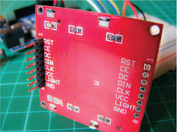
This project connects to +3.3V on the Arduino, rather than +5V.
THE BUILD
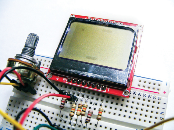
Insert the Nokia 5110 screen into the breadboard.
The Nokia screen has eight pins. Insert a 10k-ohm resistor for Nokia pins 1, 3, 4, and 5, making sure they straddle the center break. Insert a 1k-ohm resistor for Nokia pins 2 and 7, as shown in Figure 18-2.
FIGURE 18-2: Insert the resistors for the Nokia LCD screen as shown here.
WARNING
It’s really important to use the +3.3V power from the Arduino for the Nokia 5110 screen and not +5V for this project; otherwise, you will damage the screen.
Use jumper wires to make the connections from the Nokia screen to Arduino pins 3–7 and to the breadboard power rails. Make sure to add the right value resistor to the correct pin, as shown in the following table. Some breakout boards may have the pins in different locations, so match the pin names on the Nokia screen with the Arduino pin.
NOKIA 5110 SCREEN
RESISTOR
ARDUINO
1 RESET
10k-ohm
Pin 6
2 CE
1k-ohm
Pin 7
3 DC
10k-ohm
Pin 5
4 DIN
10k-ohm
Pin 4
5 CLK
10k-ohm
Pin 3
6 VCC
None
+3.3V
7 Light
1k-ohm
GND
8 GND
None
GND
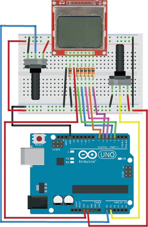
Insert the potentiometers into the breadboard as shown in Figure 18-3. Connect the center pin of one potentiometer to Arduino A0 and the center pin of the other potentiometer to Arduino A1. Connect an outer pin of each potentiometer to the +5V rail of the breadboard and the other outer pins to the GND rail.
Connect the power rails of the breadboard to +5V and GND on the Arduino (this is for the potentiometers only).
Confirm that your setup matches Figure 18-3, and upload the code in “The Sketch” below.
FIGURE 18-3: The circuit diagram for the Nokia 5110 LCD Screen Pong Game
THE SKETCH
The game starts with two bars on opposite sides of the screen and a ball bouncing between them. The object of the game is to use the potentiometers to move the bars like paddles, hitting the ball back and forth to stop it from going out of the play (beyond the screen perimeter). The ball bounces off the bars and gradually gets faster and faster. The game is over when the ball goes beyond the screen limit, at which point the display will invert and the game will start over again. Note that the ball can appear quite faint the faster it moves, due to the limitation of the screen graphics.
The first part of the sketch defines the pins connected to the Nokia 5110 LCD screen. It then defines the size of the screen, which is the area of our game that counts as in-play, and the size and starting positions of the bars and ball. The potentiometers read the analog signal from Arduino pins A0 and A1 and move their corresponding bars onscreen depending on how they’re twisted. The calculations that follow determine whether the ball and the bar have met at certain coordinates. If they have, the ball bounces back; if they haven’t, it means the bar has missed the ball, so the screen inverts and flashes to indicate the game is over.
// Arduino Pong by Onur Avun and reproduced with kind permission
#define PIN_SCE 7
#define PIN_RESET 6
#define PIN_DC 5
#define PIN_SDIN 4
#define PIN_SCLK 3
#define LCD_C LOW
#define LCD_D HIGH
#define LCD_X 84
#define LCD_Y 6
int barWidth = 16;
int barHeight = 4;
int ballPerimeter = 4;
unsigned int bar1X = 0;
unsigned int bar1Y = 0;
unsigned int bar2X = 0;
unsigned int bar2Y = LCD_Y * 8 - barHeight;
int ballX = 0;
int ballY = 0;
boolean isBallUp = false;
boolean isBallRight = true;
byte pixels[LCD_X][LCD_Y];
unsigned long lastRefreshTime;
const int refreshInterval = 150;
byte gameState = 1;
byte ballSpeed = 2;
byte player1WinCount = 0;
byte player2WinCount = 0;
byte hitCount = 0;
void setup() {
LcdInitialise();
restartGame();
}
void loop() {
unsigned long now = millis();
if (now - lastRefreshTime > refreshInterval) {
update();
refreshScreen();
lastRefreshTime = now;
}
}
void restartGame() {
ballSpeed = 1;
gameState = 1;
ballX = random(0, 60);
ballY = 20;
isBallUp = false;
isBallRight = true;
hitCount = 0;
}
void refreshScreen() {
if (gameState == 1) {
for (int y = 0; y < LCD_Y; y++) {
for (int x = 0; x < LCD_X; x++) {
byte pixel = 0x00;
int realY = y * 8;
// Draw ball if in frame
if (x >= ballX && x <= ballX + ballPerimeter -1 && ballY +
ballPerimeter > realY && ballY < realY + 8 ) {
byte ballMask = 0x00;
for (int i = 0; i < realY + 8 - ballY; i++) {
ballMask = ballMask >> 1;
if (i < ballPerimeter)
ballMask = 0x80 | ballMask;
}
pixel = pixel | ballMask;
}
// Draw bars if in frame
if (x >= bar1X && x <= bar1X + barWidth -1 && bar1Y +
barHeight > realY && bar1Y < realY + 8 ) {
byte barMask = 0x00;
for (int i = 0; i < realY + 8 - bar1Y; i++) {
barMask = barMask >> 1;
if (i < barHeight)
barMask = 0x80 | barMask;
}
pixel = pixel | barMask;
}
if (x >= bar2X && x <= bar2X + barWidth -1 && bar2Y +
barHeight > realY && bar2Y < realY + 8 ) {
byte barMask = 0x00;
for (int i = 0; i < realY + 8 - bar2Y; i++) {
barMask = barMask >> 1;
if (i < barHeight)
barMask = 0x80 | barMask;
}
pixel = pixel | barMask;
}
LcdWrite(LCD_D, pixel);
}
}
} else if (gameState == 2) {
}
}
void update() {
if (gameState == 1) {
int barMargin = LCD_X - barWidth;
int pot1 = analogRead(A0); // Read pots and set bar positions
int pot2 = analogRead(A1);
bar1X = pot1 / 2 * LCD_X / 512;
bar2X = pot2 / 2 * LCD_X / 512;
if (bar1X > barMargin) bar1X = barMargin;
if (bar2X > barMargin) bar2X = barMargin;
// Move the ball now
if (isBallUp)
ballY -= ballSpeed;
else
ballY += ballSpeed;
if (isBallRight)
ballX += ballSpeed;
else
ballX -= ballSpeed;
// Check collisions
if (ballX < 1) {
isBallRight = true;
ballX = 0;
}
else if (ballX > LCD_X - ballPerimeter - 1) {
isBallRight = false;
ballX = LCD_X - ballPerimeter;
}
if (ballY < barHeight) {
if (ballX + ballPerimeter >= bar1X && ballX <= bar1X + barWidth) {
// Ball bounces from bar1
isBallUp = false;
if (ballX + ballPerimeter / 2 < bar1X + barWidth / 2)
isBallRight = false;
else
isBallRight = true;
ballY = barHeight;
if (++hitCount % 10 == 0 && ballSpeed < 5)
ballSpeed++;
} else { // Player 2 wins
gameState = 2;
player2WinCount++;
}
}
if (ballY + ballPerimeter > LCD_Y * 8 - barHeight) {
if (ballX + ballPerimeter >= bar2X && ballX <= bar2X + barWidth) {
// Ball bounces from bar2
isBallUp = true;
if (ballX + ballPerimeter / 2 < bar2X + barWidth / 2)
isBallRight = false;
else
isBallRight = true;
ballY = LCD_Y * 8 - barHeight - ballPerimeter;
if (++hitCount % 10 == 0 && ballSpeed < 5)
ballSpeed++;
} else { // Player 1 wins
gameState = 2;
player1WinCount++;
}
}
} else if (gameState == 2) {
for (int i =0; i < 4; i++) {
LcdWrite(LCD_C, 0x0D); // LCD in inverse mode.
delay(300);
LcdWrite(LCD_C, 0x0C); // LCD in inverse mode.
delay(300);
}
restartGame();
}
}
void LcdInitialise(void) {
pinMode(PIN_SCE, OUTPUT);
pinMode(PIN_RESET, OUTPUT);
pinMode(PIN_DC, OUTPUT);
pinMode(PIN_SDIN, OUTPUT);
pinMode(PIN_SCLK, OUTPUT);
delay(200);
digitalWrite(PIN_RESET, LOW);
delay(500);
digitalWrite(PIN_RESET, HIGH);
LcdWrite(LCD_C, 0x21 ); // LCD Extended Commands
LcdWrite(LCD_C, 0xB1 ); // Set LCD Vop (Contrast)
LcdWrite(LCD_C, 0x04 ); // Set Temp coefficent. //0x04
LcdWrite(LCD_C, 0x14 ); // LCD bias mode 1:48. //0x13
LcdWrite(LCD_C, 0x0C ); // LCD in normal mode.
LcdWrite(LCD_C, 0x20 );
LcdWrite(LCD_C, 0x80 ); // Select X Address 0 of the LCD ram
LcdWrite(LCD_C, 0x40 ); // Select Y Address 0 of the LCD ram
LcdWrite(LCD_C, 0x0C );
}
void LcdWrite(byte dc, byte data) {
digitalWrite(PIN_DC, dc);
digitalWrite(PIN_SCE, LOW);
shiftOut(PIN_SDIN, PIN_SCLK, MSBFIRST, data);
digitalWrite(PIN_SCE, HIGH);
}
TROUBLESHOOTING
Q. Nothing is displayed on the LCD screen.
• Make sure you’ve connected power to the LCD screen direct to the Arduino +3.3V power pin and the connections match the tables in this chapter.
• Make sure your resistors line up with the correct LCD pins, as well as the wires to the Arduino pins.
• If the backlight of the LCD screen is lit but there is no image, you may have some wires mixed up; they need to match the circuit in Figure 18-3 exactly.
Q. When the player turns the potentiometer, one or both of the bars do not move.
• Make sure the potentiometers are connected firmly in the breadboard and that the wires connecting to the power rails and Arduino line up with the potentiometer pins.
• Remember that the potentiometers require +5V power and GND from the Arduino. These pins should be hooked up to the breadboard power rails via jumper wires.
• Make sure you also use jumper wires to connect the corresponding power rails on either side of the breadboard to each other.