
17
Ultrasonic People Counter
This project teaches you how to use the HC-SR04 ultrasonic sensor to sense when people pass and then show that count on a serial LCD screen.


PARTS REQUIRED
Arduino board
Mini-breadboard
Jumper wires, male-to-male and female-to-male
LED
Serial LCD screen module
220-ohm resistor
HC-SR04 ultrasonic sensor
LIBRARIES REQUIRED
NewPing
Wire
LiquidCrystal_I2C
HOW IT WORKS
People counters are often used in shops or tourist attractions to count the number of visitors, but you could also use one to record the volume of traffic on a highway or in a parking lot, or to count how many times someone entered your room while you were out!
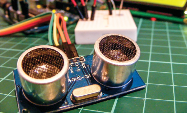
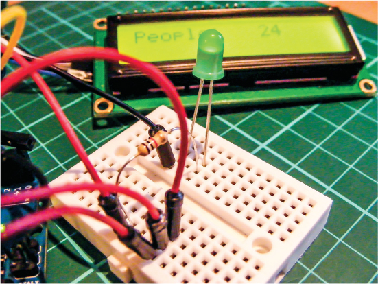
The ultrasonic sensor we’ll use is the HC-SR04, shown in Figure 17-1, which you first saw in Project 13. It uses an ultrasonic signal, or ping, to calculate the distance between the sensor and an object. In this project we’ll use this function to count every time someone or something passes in front of the sensor. An LED will flash when a count is registered, and the serial LCD screen will show the total number counted.
FIGURE 17-1: The HC-SR04 ultrasonic sensor uses a ping to calculate distances.
THE BUILD
Use the female-to-male jumper wires to connect the HC-SR04 ultrasonic sensor to the Arduino with the VCC pin to Arduino +5V, GND to GND, and Trig and Echo to pins 7 and 8 on the Arduino, respectively, as shown in the following table and in Figure 17-2. Use the mini-breadboard for multiple connections.
ULTRASONIC SENSOR
ARDUINO
VCC
+5V
Trig
Pin 7
Echo
Pin 8
GND
GND
FIGURE 17-2: The connections from the ultrasonic sensor

Make sure to download the LiquidCrystal I2C and NewPing libraries and add them to the relevant folder on your computer (see the primer for guidance). The Wire library comes with the Arduino IDE, so you do not need to add it.
Connect the serial LCD screen to the Arduino as follows, using the mini-breadboard to connect to +5V.
SERIAL LCD SCREEN
ARDUINO
GND
GND
VCC
+5V
SDA
Pin A4 (SDA)
SCL
Pin A5 (SCL)
Insert the LED into the mini-breadboard so that the shorter, negative (GND) leg is to the left and the longer, positive (+5V) leg is to the right, as shown in the following table and in Figure 17-3. Connect the 220-ohm resistor to the positive leg of the LED, making sure the other leg of the resistor straddles the break in the breadboard. Connect this other resistor leg to pin 13 on the Arduino. Connect the shorter leg of the LED to GND on the Arduino.
LED
ARDUINO
GND
GND
+5V
Pin 13 via 220-ohm resistor
FIGURE 17-3: We use the mini-breadboard to hold the LED and for multiple connections to the Arduino +5V.
Make sure your final circuit looks like Figure 17-4, and then upload the code in “The Sketch” on page 146 to the Arduino.
FIGURE 17-4: The circuit diagram for the ultrasonic people counter

THE SKETCH
The sketch begins by calling on the LiquidCrystal I2C, NewPing, and Wire libraries to control the serial LCD screen and ultrasonic sensor. Next it defines the ultrasonic sensor Trig and Echo pins as Arduino pins 7 and 8, respectively. We set the maximum distance for the sensor to read to 200 centimeters (any reading beyond 200 centimeters is ignored). Then we define pin 13 on the Arduino as the LED, which will be our counting indicator, and create variables to hold the distance and number of people. We create a count state so the Arduino can determine a valid record, and then we define the type of LCD screen. We initiate the LCD screen so that People: is printed to the screen, and set the LED pin as an output.
The loop section sends a ping from the sensor and if the ping that’s returned is from a distance of more than 100 centimeters, the space in front of the sensor is considered empty and nothing is registered. If the distance recorded is less than 100 centimeters, it means something is within range in front of the sensor. In order for the people: variable to increment, someone has to move in front of the sensor, then out of the way. The sensor will keep counting every time a valid register is received, and the latest total is shown on the LCD screen.
The sensor could be placed to one side of an entrance, facing across the threshold, so as someone enters the sensor picks it up and registers a count. If the sensor is pointing toward a wall that’s less than 100 centimeters away, you’ll need to change the following line of code to a distance less than the distance to the wall; otherwise, the sensor will record a count every time the wall is detected.
if (distance < 100 && distance != 0 && !count)
Here is the full code:
#include <LiquidCrystal_I2C.h> // Call on the libraries
#include <NewPing.h>
#include <Wire.h>
#define TRIGGER_PIN 7 // Ultrasonic sensor trig to Arduino pin 7
#define ECHO_PIN 8 // Ultrasonic sensor echo to Arduino pin 8
#define MAX_DISTANCE 200
NewPing sonar(TRIGGER_PIN, ECHO_PIN, MAX_DISTANCE);
int LEDPin = 13; // Set LED to pin 13
int distance; // Variable for distance
int people = 0; // Variable for number of people
boolean count = false; // State for counting
LiquidCrystal_I2C lcd(0x27, 16, 2);
void setup() { // Run once to set up the LCD screen and LED
lcd.begin();
lcd.backlight();
pinMode(LEDPin, OUTPUT); // Set the LED as an output
lcd.print("People:"); // Print People: to the LCD screen
}
void loop() { // This loops forever to check for number of people
delay(50);
distance = sonar.ping_cm(); // Ping every 50 milliseconds
// If more than 100 cm away, don't count
if (distance > 100 && count) {
count = false;
digitalWrite(LEDPin, LOW);
}
// If less than 100 cm away, count 1
if (distance < 100 && distance != 0 && !count) {
count = true;
people ++; // Keep adding 1 per count
digitalWrite(LEDPin, HIGH);
lcd.setCursor(10, 0);
lcd.print(people); // Print number of people to LCD screen
}
}
TROUBLESHOOTING
Q. The code compiles, but nothing shows on the screen.
• Double-check that the SDA and SCL pins are connected to the correct Arduino pins.
• If the LCD screen is lit up but nothing shows, carefully turn the small potentiometer at the back of the module to change the contrast until the letters appear.
Q. The sensor does not register a count or the LED does not light when expected.
• Make sure that the ultrasonic sensor trigger pin is connected to Arduino pin 7 and the Echo pin to Arduino pin 8, and that power is connected to GND and +5V.
• If a count is registered and the LED does not light, recheck that the short leg of the LED is connected to GND and the long leg to +5V. The resistor should straddle the break in the breadboard and be connected to the LED’s long leg on one side and Arduino pin 13 on the other.
• Remember that the positioning of the sensor is important. If the distance to a fixed object (like a wall) is less than the distance in the sketch, the count will be incorrect.
• Your device may have a different address than the one we’ve used here. To check the address of your device, use the I2C scanner sketch available on the Arduino website (http://playground.arduino.cc/Main/I2cScanner). Run the sketch with your device attached to the Arduino and open the IDE Serial Monitor, and you should see the address of your device. Update the following line in this sketch with the address shown:
LiquidCrystal_I2C lcd(0x27,16,2);