
AutoCAD and AutoCAD LT offer a number of complex objects that can help you create accurate, professional drawings. Polylines are single objects that can combine line segments and arcs. Splines are mathematically controlled curves that are based on points that you specify. Regions and boundaries create complex shapes from existing objects. Hatches create various types of fills inside closed objects. Multilines (in AutoCAD) and dlines (in AutoCAD LT) are sets of parallel lines. Sketching is a way to create freehand drawings. Digitizing with a tablet is a process that is used to transfer an existing paper drawing into your drawing. In this chapter, I introduce you to these complex objects and explain how to use them.
Polylines are single objects that combine line segments and arcs. In certain situations, being able to edit an entire set of lines and arcs as one object is useful. Polylines can have a width, which can vary from the start point to the endpoint of each segment. Polylines ensure that all the vertices of a series of lines and arcs actually touch. They're also useful for 3D drawing. In short, polylines are a neat, clean way to draw.
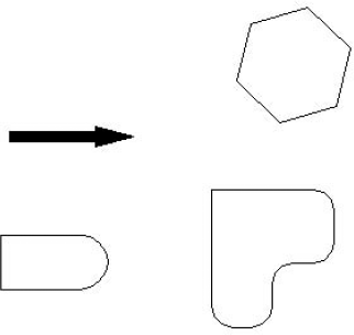
The RECTANG and POLYGON commands create polylines. Figure 16.1 shows a few examples of polylines.
Arc. Draws arcs. This option opens up a set of arc suboptions, which are explained after this list.
Close. Closes a polyline by drawing a line from the endpoint of the last line segment to the start point of the polyline. This option appears only after you've picked a second point.
Halfwidth. Defines half of the width of the polyline — the distance from the center of the polyline to its edge. The option asks you for the starting halfwidth and the ending halfwidth, enabling you to create polylines that are tapered.
Length. Specifies the length of the next line segment. The option draws the line segment in the same direction as the last line segment or tangent to the last arc.
Undo. Undoes the last line segment.
Width. Defines the width of the polyline. The option asks you for the starting width and the ending width.
Specify next point. Enables you to create a line segment. This is the default option.
Like the LINE command, PLINE continues to prompt you for more points, repeating the entire prompt each time. When you're done, press Enter to end the command.
If you choose Arc, you see the Specify endpoint of arc or [Angle/CEnter/CLose/Direction/Halfwidth/Line/Radius/Second pt/ Undo/Width]: prompt. Most of the options are similar to the ARC command options. For details, see Chapter 7. The arc options are as follows:
Angle. Specifies the included angle.
CEnter. Specifies the arc's center.
CLose. Closes the polyline by drawing an arc from the endpoint of the last arc to the start point of the polyline.
Direction. Specifies the direction of the arc from the start point.
Halfwidth. Defines half of the width of the polyline — the distance from the center of the polyline to its edge. The option asks you for the starting halfwidth and the ending halfwidth.
Line. Returns you to the main polyline prompt so that you can draw line segments.
Radius. Specifies the arc's radius.
Second pt. Specifies the second point of the arc.
Undo. Undoes the last arc.
Width. Defines the width of the polyline. The option asks you for the starting width and the ending width.
Specify endpoint of arc. Specifies the endpoint of the arc. This is the default. This option creates an arc tangent to the previous arc (continuing in the same direction).
PLINE continues to display the arc submenu until you use the Line suboption or end the command by pressing Enter.
The drawing used in the following exercise on drawing polylines, ab16-a.dwg, is in the Drawings folder on the DVD.
STEPS: Drawing Polylines
Open
ab16-a.dwgfrom your DVD.Save the file as
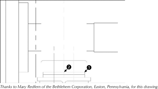
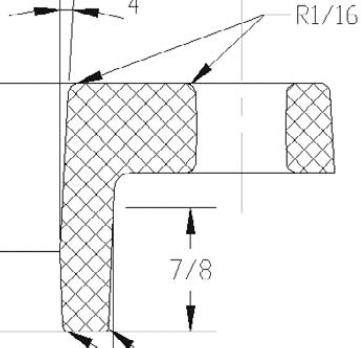
ab16-01.dwgin yourAutoCAD Biblefolder. It shows a small section of a drive block, as shown in Figure 16.2. In this exercise, you complete part of the drawing. Ortho Mode and Object Snap should be on. Set running object snaps to Endpoint, Midpoint, and Intersection. Layer 3 is current. This exercise assumes that you have Dynamic Input (the Dynamic Input button on the status bar) on, set to the default of relative coordinates.
Specify start point:
Press Shift+right-click and choose the From object snap. Base point:Choose
in Figure 16.2. <Offset>:@−1/2,0Specify next point or [Arc/ Halfwidth/Length/Undo/Width]:
Move the cursor in the 90-degree direction and type3/32.Type a
Type l
Type a
Type l
Type a
To create the last arc, type r
Specify radius of arc:
5-5/8Specify endpoint of arc or [Angle]:Choose the From object snap. Base point:Choose point
in Figure 16.2. <Offset>:@0,7-1/4Press Enter to exit the PLINE command.
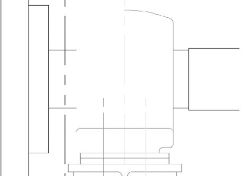
Save your drawing. It should look like Figure 16.3.
Generating linetypes on polylines
When you create a polyline with a noncontinuous linetype, you may find that the linetype doesn't appear properly along the polyline. One reason is that the segments of the polyline may be too short to fit the entire linetype definition — in this case the polyline appears continuous. You can choose to generate the linetype continuously along the polyline, instead of starting the linetype definition anew at each vertex. This results in a more normal-looking linetype along the polyline. To do this, you need to turn on the PLINEGEN system variable. To turn on PLINEGEN, type plinegen
As explained in the section "Editing polylines with the PEDIT command" later in the chapter, you can also modify the display of linetypes for existing polylines.
Note
Ar1 creates a label of the area of an enclosed polyline. Look in SoftwareCh16ar1. Note that you can also create a similar label by using the area field. I cover fields in Chapter 13.
Close. Closes an open polyline. If necessary, it adds a segment to connect the endpoint to the start point. If the polyline is already closed, this prompt becomes Open. Open creates a break between the first and last segments of the polyline.
Join. Joins touching lines, arcs, or other polylines to the polyline.
Width. Enables you to specify one width for the entire polyline.
Edit Vertex. Provides a set of suboptions for editing vertices. These suboptions are explained after this list.
Fit. Turns the polyline into a curve that passes through the vertices.
Spline. Creates a curve by using the vertices as control points. The curve does not usually pass through the vertices. This is not the mathematically exact spline that the SPLINE command produces (covered later in this chapter).
Decurve. Returns a Fit or Spline curve to its original vertices.
Ltype gen. Turns on continuous linetype generation for the selected polyline.
Reverse. Reverses the direction of the polyline so that the starting point becomes the end point, providing more control of the display of special linetypes.
Undo. Undoes the most recent edit.
Tip
You can change any line, spline, or arc into a polyline. Start PEDIT and choose a line or arc. The command responds: Object selected is not a polyline. Do you want to turn it into one? <Y>. Press Enter to accept the default and turn the object into a polyline. (You can change the PEDITACCEPT system variable to 1 to suppress this prompt and automatically turn non-polyline objects that you select for the PEDIT command to polylines.)
To turn a series of connected lines and arcs into a polyline, first turn one of the objects into a polyline as I just explained. Then use the Join option and select the other objects individually or by a selection window. In order to create a polyline in this way, the individual lines and arcs must connect exactly end to end. However, if you use the Multiple option, which I explain following the current list, you can join lines that aren't exactly touching.
Note
You can now convert a spline to a polyline, using the PEDIT command. When doing so, you get a prompt to enter a precision value between 0 and 99. A higher number provides a more accurate conversion. You can also change the new system variable PLINECONVERTMODE to 0 to convert polylines to linear segments, or leave it at 1 (the default) to use arcs. If you want to keep the original spline along with the new polyline, change the system variable DELOBJ to 0 (off) before making the conversion.
When you choose the Edit Vertex option, you see a new set of suboptions with the Enter a vertex editing option [Next/Previous/Break/Insert/Move/Regen/Straighten/Tangent/Width/eXit] <N>: prompt. You see an X at one of the vertices. This is the current vertex, which you can edit. The suboptions are as follows:
Next. Moves you to the next vertex so that you can edit it.
Previous. Moves you to the previous vertex.
Break. Breaks the polyline. You can choose the Go suboption to break the polyline into two (although you can't see the break). You can move to another vertex by using the Next or Previous suboptions and then choosing Go. This option breaks the polyline between the original vertex and the vertex to which you moved. Use the eXit suboption to return to the previous prompt. (You can also use the BREAK command.)
Insert. Inserts another vertex. At the prompt, specify its location.
Move. Moves the vertex. At the prompt, specify its location.
Regen. Regenerates the polyline.
Straighten. Deletes vertices. This works like the Break option with the same Next, Previous, Go, and eXit suboptions. As soon as you move to a new vertex, the option draws a straight line between it and the original vertex. If you don't move to a new vertex, this option affects only an arc by changing it to a straight line segment.
Tangent. Specifies a direction from the vertex. The command uses this information if you choose the Fit option.
Width. Enables you to specify starting and ending widths of the segment, starting with the current vertex.
eXit. Exits this group of suboptions.
Warning
You can make many changes during the PEDIT session. If you return to the command line and use the U or UNDO command, the entire session is undone. If you want to undo only part of the session, use the Undo option of the PEDIT command.
You can also edit polylines with grips. A polyline has a grip at each vertex, making it easy to move vertices.
To edit multiple polylines at one time, follow these steps:
Start the PEDIT command.
Choose the Multiple option (type m
At the
Select objects:prompt, select the polylines.You then see the
Enter an option [Close/Open/Join/Width/Fit/Spline/Decurve/Ltype gen/Undo]:prompt.Choose the option that you want. For example, you can change the width of all the selected polylines or apply the Spline option to them.
You can also join two polylines that aren't touching, if you use the Multiple option first. Select the polylines and then choose the Join option. You then need to specify two suboptions:
Fuzz distance. The maximum distance that the endpoints of the polylines can be from each other. In other words, in order for the join to work, the fuzz distance must be greater than the distance of the endpoints. If you want to join the endpoints regardless, type in a large number.
Jointype. The method of joining polylines. You can use the Extend method, which extends (or trims) the segments to the nearest endpoints, or the Add method, which adds a straight segment between the two nearest endpoints. You can choose the Both suboption, which tries to extend or trim; if it can't, it adds a segment.
You can edit selected polylines in the Properties palette. You can choose a vertex by clicking Vertex in the Geometry section of the palette, and use the left and right arrows to move to another vertex. An X appears on the polyline to let you know which vertex you've chosen. You can then edit the vertex's coordinates by typing them in, or by clicking the Pick a Point button that appears and then picking a point in the drawing. You can change the start and ending widths and specify a global width for the entire polyline.
You can close and open a polyline in the Misc section. You can also turn on continuous linetype generation for the selected polyline by choosing Linetype generation and then choosing Enabled from the drop-down list that appears. Of course, you can also change the layer, color, linetype, lineweight, and linetype scale.
Note
The drawing used in the following exercise on editing polylines, ab16-b.dwg, is in the Drawings folder on the DVD.
STEPS: Editing Polylines
Open
ab16-b.dwgfrom your DVD.Save the file as
ab16-02.dwgin yourAutoCAD Biblefolder. This is a topographical drawing, as shown in Figure 16.4. The contours are polylines.
At the Enter an option [Close/Join/Width/Edit vertex/Fit/Spline/Decurve/Ltype gen/Undo]: prompt, right-click and choose Width. At the Specify new width for all segments: prompt, type .5
Type e
Type m to move the vertex. At the
Specify new location for marked vertex:prompt, pick a point slightly above the existing vertex. Then type xAt the main PEDIT prompt, type s
Press Enter to exit the PEDIT command.
Save your drawing.
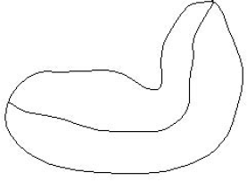
The SPLINE command draws a NURBS, which stands for nonuniform rational B-spline. A spline is a smooth curve that is defined by a series of points. The SPLINE command provides a more precise representation of a spline than the Spline option of the PLINE command. By default, the curve passes through each point that you define. Figure 16.5 shows a beanbag chair created with two splines.
If you choose a point, the command displays the Specify next point: prompt so that you can pick a second point. After you do so, you see the Specify next point or [Close/Fit tolerance] <start tangent>: prompt. Use these options as follows:
Close. Closes the spline by connecting the last point with the first point in a continuous (tangent) curve. The prompt asks for a tangent direction. You can specify a direction by picking a point (watch the spline image change as you move the cursor) or pressing Enter to accept the default tangent direction.
Fit Tolerance. Specifies how closely the spline comes to the points that you pick. The default, 0, creates a spline that passes through each point. If you want the curve to have a latitude of 0.5 units from the points, set the tolerance to 0.5.
Specify next point. The default option is to continue entering points. Press Enter to end point selection.
Start tangent. When you press Enter to complete point selection, you're prompted for start and ending tangent directions. You can press Enter at both prompts to accept the default tangents, based on the curve's current shape. You can see the effect of other tangent points by moving the cursor and watching the image change.
Note
The drawing used in the following exercise on drawing splines, ab16-c.dwg, is in the Drawings folder on the DVD.
STEPS: Drawing Splines
Open
ab16-c.dwgfrom your DVD.Save the file as
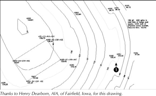
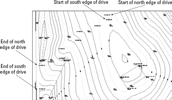
ab16-03.dwgin yourAutoCAD Biblefolder. This is a topographical site map, as shown in Figure 16.6. Object Snap should be on. Set a running object snap for Insertion.
At the
Specify first point or [Object]:prompt, use the Insertion object snap to pick the cross at the start of the north edge of the drive, as shown in Figure 16.6. Continue to pick the crosses marked N-EDGE-DR. Choose Pan from the status bar to do a real-time pan when you reach the edge of the display. Press Esc. Continue picking points until you get to the end of the north edge of the drive, as shown in Figure 16.6. Press Enter to end point selection.At the
Specify start tangent:andSpecify end tangent:prompts, press Enter.Start the SPLINE command again and pick points for the south edge of the drive, from the start of the south edge of the drive to the end, as shown in Figure 16.6. Pan as necessary. Again, press Enter to accept the default directions for the start and end tangents.
If you want, Zoom Previous several times until you see the original view of the drawing. Save your drawing.
Note
GeomCurves.lsp is a routine that creates various kinds of geometrical curves, such as spirals and parabolas. You can find it in the SoftwareChapter 16GeomCurves folder.
Like polylines, splines have their own editing command. To understand how to edit splines, you need to understand how your drawing stores them.
When you pick points to create the spline, AutoCAD stores these points as fit points (or data points). If the tolerance is zero, the curve lies on these fit points. When you select a spline at the command line, grips appear at these fit points. However, when you use the SPLINEDIT command, to see the fit points as grips, you must choose the Fit Data option first. Only then can you edit the fit points.
AutoCAD and AutoCAD LT calculate control points based on the fit points. The spline is then calculated based on the control points, not the fit points. Most of the control points are not on the spline. When you use SPLINEDIT to edit a spline, and use the Move vertex option described later, you see the control points displayed as grips, and you can move the control points.
The left side of Figure 16.7 shows a spline created by using point objects as the fit points; these are the points that were picked when creating the spline. Note that the spline passes through each fit point. On the right, you see the same spline selected with no command active. Notice that the grips are exactly on the fit points.
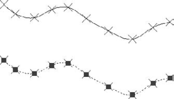
Figure 16.7. On the top, you see the point objects that were used as the pick points. These are the fit points of the spline. On the bottom, you see the spline with no command active, and the grips are on the fit points.
Because the spline is calculated based on the control points, the fit points are not necessary to generate the spline. In fact, if you use the Move vertex or Refine options to move or edit a control point, only the control points are needed to generate the spline, and the fit point information is discarded so that you can no longer edit it. The Fit Data option also disappears from the prompt. You can edit the fit points by using grips.
To edit a spline, choose Home tab
Fit Data. Fit data means the points that you specified, their tolerance, and the tangents. Use this option to edit fit data. This option has its own list of suboptions that are explained after this list.
Close/Open. If the spline is open, this option closes it by adding a continuous (tangent) curve from the last point to the start point. If the spline is closed, this option appears as Open. If the spline was originally closed, the Open option removes the connection between the last and first points, although the spline looks the same. If the spline was originally open and you closed it, when you use the Open option, this option erases the curve that it added when you closed it.
Move Vertex. This works like the Edit vertex option of PEDIT (covered previously in this chapter), but it displays the points as grips and highlights them. You can use Next and Previous suboptions, select any point to move, and pick a new location for the highlighted vertex.
Refine. Enables you to refine the spline in three ways:
Add control points. This doesn't change the shape of the spline but adjusts nearby control points slightly.
Elevate the order of the spline. This adds control points throughout the spline (but once you go up, you can't go down).
Change the weight of any control point. This is like the gravity that the control point exerts on the spline. Watch the spline inch toward the control point as you increase its weight.
rEverse. Reverses the direction of the spline so that the start point becomes the endpoint, and vice versa.
convert to Polyline. Changes the spline to a polyline. The prompt asks you to specify a conversion precision. Enter a value between 0 and 99. A higher value results in a more accurate polyline.
Undo. Undoes the most recent edit operation.
When you use the SPLINEDIT command and select a spline, you see control points, not fit points. In Figure 16.8, the grips indicate the control points.
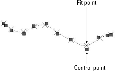
Figure 16.8. When you choose the SPLINEDIT command and select a spline, the grips indicate the control points, which are not generally on the spline.
If you choose the Fit Data option, you see the Enter a fit data option [Add/Close/Delete/Move/Purge/Tangents/toLerance/eXit] <eXit>: prompt. Descriptions of these options follow:
Add. Adds fit data points to the curve. The prompt asks you to select a point and then automatically selects the next point as well, shown with highlighted grips. At the prompt for a new point, which must be between the two highlighted points, the spline reshapes accordingly.
Open/Close. Opens or closes the spline by using the fit points.
Delete. Deletes a selected fit point.
Move. Moves a fit point. You can use the Next or Previous suboptions or the Select Point option to select the point that you want to move. Selected points appear as highlighted grips. You get a prompt for the new fit point location. You can also use grips to edit fit points.
Purge. Deletes fit point information.
Tangents. Enables you to specify start and end tangents of open splines, or one tangent for closed splines. If you don't use this option, a default tangent is calculated.
toLerance. Enables you to specify the tolerance, which determines how closely the spline comes to the fit points.
eXit. Exits the suboption menu.
When you use SPLINEDIT and choose the Fit Data option, the grips appear on the fit points so that you can edit them. You can edit a spline in the Properties palette or the Quick Properties palette. It works similarly to editing a polyline. The Properties palette displays the fit points or the control points so that you can change them.
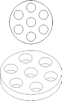
Regions are two-dimensional surfaces. They look like closed polylines, but your drawing can calculate more information from regions than from polylines, such as the centroid, moments of inertia, and other properties relating to mass. You can also create complex shapes by combining, subtracting, and intersecting regions. The REGION command is helpful as a preparation for 3D drawing.
You create a region from closed polylines, closed splines, circles, ellipses, and combinations of lines, arcs, and elliptical arcs that create a closed shape. The shape cannot intersect itself like a figure-8.
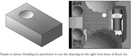
Figure 16.9 shows a complex region on the left. Although it looks like a circle with seven circles inside it, it's actually a circular surface with seven holes in it. When you select it, you can see that it's one object. The real proof is when you try to extrude it to create a 3D object out of it. You can then view it at an angle, hide background lines, and clearly see the holes, as shown on the right.
1 loop extracted.
1 Region created.
The original objects are deleted. If your objects aren't perfectly end-to-end, the prompt merely states:
0 loops extracted.
0 Regions created.
Tip
If you want to keep the original objects when converting closed shapes to a region, change the DELOBJ system variable to 0 (off) before you use the REGION command. The DELOBJ system variable determines whether objects that are used to create other objects are deleted.
The BOUNDARY command (see the next section) offers a way to create regions in situations where objects are not neatly drawn end to end.
If you had a hatch inside the objects, you lose hatch associativity. You can rehatch the region if you want.
Note
The XEDGES command extracts the edges of a region. For example, if you create a closed polyline of line and arc segments and make a region out of it, you can then use the XEDGES command to change the region to individual lines and arcs. (The EXPLODE command would have the same effect.) I discuss the XEDGES command more in Chapter 24, because it can also extract edges from solids.
You can combine, subtract, and intersect regions to create complex objects. The three commands to accomplish these functions are UNION, SUBTRACT, and INTERSECT. These commands are discussed in Chapter 24 because they're most common in 3D modeling.
Note
The drawing used in the following exercise on creating regions, ab16-d.dwg, is in the Drawings folder on the DVD.
STEPS: Creating Regions
Open
ab16-d.dwgfrom your DVD.Save the file as
ab16-04.dwgin yourAutoCAD Biblefolder.
7 loops extracted.
7 Regions created.
Save your drawing.
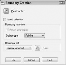
Follow these steps:
If you want the command to detect internal closed areas, leave the Island Detection check box checked. Otherwise, uncheck this check box.
The Object Type drop-down list determines the type of object that BOUNDARY creates. Choose either Region or Polyline.
Choose the boundary set, which is the area to include in the analysis for the boundary. Usually, you can accept the default of Current viewport. However, if you have a very complex drawing, choose New to temporarily return to your drawing. Specify a window around the area that you want for the boundary set. The command then returns you to the dialog box.
To specify the enclosed area for the boundary, choose Pick Points. You return to your drawing with the
Pick internal point:prompt.Pick any point inside the closed area that you want for your boundary. The command analyzes the area that you picked.
You then get a prompt for another internal point. If you want to create other boundaries, continue to pick internal points. Press Enter to end point selection.
When BOUNDARY creates a region or polyline, the original objects remain. You end up with a region or polyline on top of your original objects.
Note
The drawing used in the following exercise on creating boundaries, ab16-e.dwg, is in the Drawings folder on the DVD.
Open
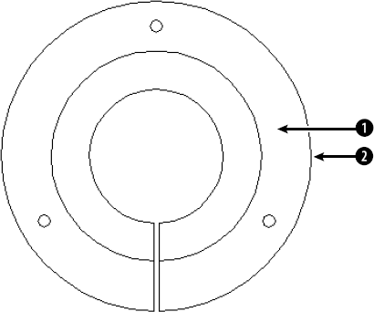
ab16-e.dwgfrom your DVD.Save the file as
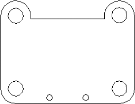
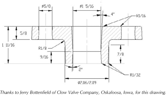
ab16-05.dwgin yourAutoCAD Biblefolder. This is a bushing, as shown in Figure 16.12.
Choose Pick Points.
At the
Pick internal point:prompt, choosePress Enter to end internal point selection. The prompt responds:
4 loops extracted.
4 Regions created.
BOUNDARY created 4 regions
To see the new region, start the MOVE command. At the
Select objects:prompt, pickSave your drawing.
Hatches are patterns that fill in an area. Most types of drafting make use of hatching. In architectural drafting, hatched areas are used to indicate materials, such as insulation or grass. In mechanical drafting, hatching often indicates hidden areas or certain materials. AutoCAD and AutoCAD LT provide a large number of hatch patterns. Hatches are created from repeating patterns of lines. You can create solid fills in the same way that you create hatch patterns.
Note
Chapter 31 explains how to create your own hatch patterns.
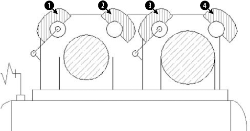
Figure 16.13 shows a drawing with a simple hatch pattern. Here the cross-section shows solid metal that is hatched to distinguish it from the holes.
Hatch patterns may seem complex, but they are easy to use, after you understand how they work. Hatch patterns have three characteristics that are similar to dimensions:
They are blocks. This means that all the lines that fill in an area are one object. Blocks are covered in Chapter 18.
They are associative. If you edit the object that is hatched, the hatch automatically adjusts to fit the new shape of the object.
They can be annotative. If you activate the annotative property of the hatch, the hatch can automatically adjust its display scale in a viewport. (See Chapter 17 for a discussion of annotative objects and viewports.)
You have several ways to specify exactly which area you want to hatch. Often, the key to successful hatching lies in how you construct the area that you want to hatch. For example, you can use the BOUNDARY and REGION commands covered in previous sections of this chapter to create complex closed areas that you can hatch.
AutoCAD stores hatch pattern definitions in the acad.pat and acadiso.pat files. AutoCAD LT uses the acadlt.pat and acadltiso.pat files. If you create your own hatch patterns, you can put them in another file with the PAT filename extension.
Tip
Create a separate layer for hatch patterns. You may want to turn off or freeze your hatch layer to reduce visual clutter or assist in selecting objects. Hatches are also typically a different color than the model that you're hatching.
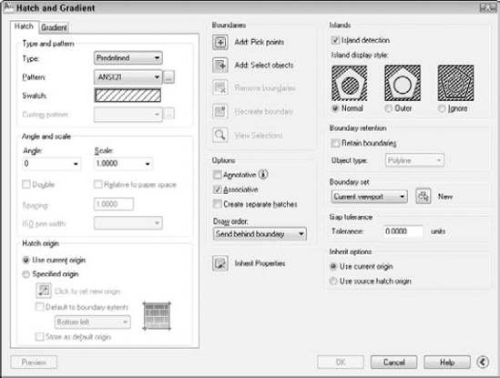
Use the Hatch and Gradient dialog box to define your hatch. From the Type drop-down list, choose one of these three options:
Predefined. Enables you to select any of the standard hatch patterns
User defined. Enables you to define your own hatch pattern by specifying the angle and spacing, using the current linetype
Custom. Enables you to choose a pattern that you've created in your own PAT file
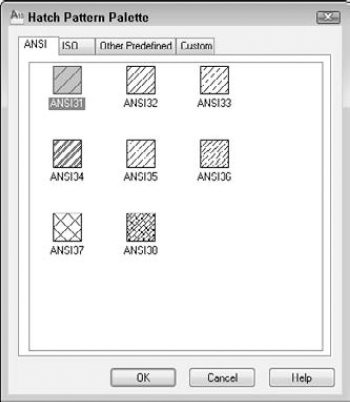
Click the Pattern drop-down list to choose the hatch patterns, or click the Ellipsis button to the right to open the Hatch Pattern palette and choose from the image tiles, as shown in Figure 16.15.
Note
Mhatch is a program that creates solid fills for a selection of closed objects. Look in SoftwareCh16mhatch. It works with AutoCAD only.
In the palette, click the tabs to see the different types of hatches. Click the image tile to choose a hatch pattern and click OK. The palette is simply another method of choosing the hatch pattern — you can also choose the pattern by using the Pattern drop-down list. The swatch shows you how your chosen hatch will look.
Note
You can drag hatches from your drawing to the Tools Palette window to create hatch tools that you can then drag into your drawing. See Chapter 26 for a description of the Tools Palette window.
The Custom Pattern drop-down list is available only if you have chosen Custom as the pattern type. Here you choose the name of your custom hatch pattern. I explain how to create custom hatch patterns in Chapter 31.
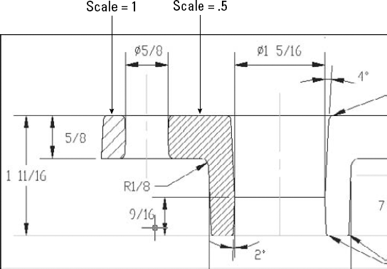
Use the Angle box to rotate the angle of the hatch pattern. You can choose from the drop-down list or type an angle. Watch out here, as many of the patterns are already defined at an angle. The hatch pattern in Figure 16.16 uses a 0-degree angle because ANSI31 is defined as diagonal lines.
The Scale box determines the scale of the hatch pattern. You can choose from the drop-down list or type a scale. A scale of 1 (the default) creates the hatch as defined. A scale of 0.5 shrinks it by one half. Figure 16.16 shows two hatch patterns using the ANSI31 pattern. The left one uses a scale of 1, and the right one uses a scale of 0.5.
The Spacing box and the Double check box are available if you have chosen User Defined as the pattern type. A user-defined hatch uses the current linetype and creates a hatch based on the spacing and angle that you specify. Figure 16.17 shows a user-defined double hatch with an angle of 45 degrees and 0.1-unit spacing.
To define a user-defined hatch pattern:
Choose Home tab

In the Type drop-down list, choose User Defined.
In the Angle box, type an angle or choose one from the drop-down list. When creating a user-defined hatch, you need to specify the actual angle that you want to see.
In the Spacing box, enter the spacing between the lines. For example, type .5 to create a hatch pattern with lines 0.5 units apart.
If you want to cross-hatch so that the parallel lines are crossed by an equal number of perpendicular lines, check Double.
The ISO Pen Width box is available only for ISO predefined hatch patterns. This feature adjusts the scale of the pattern according to the pen width that you specify. When you choose a pen width from the drop-down list, the scale shown in the Scale box automatically changes to equal the pen width. Note that you still have to separately set the width of your plotter pens when you plot your drawing.
Note
The Express Tools SUPERHATCH command creates a hatch pattern from an image, block, xref, or wipeout. Choose Express Tools tab
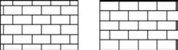
The Hatch Origin section lets you determine where the hatch pattern starts. By default, the pattern starts at the origin of the drawing, which is generally 0,0. As a result, the hatch in your object may start somewhere in the middle. This effect is very visible with certain hatch patterns, such as bricks. In Figure 16.18, you see two rectangles. The one on the left uses the default origin; the one on the right uses the lower-left corner of the rectangle as the origin.
To specify the hatch origin, choose the Specified Origin option. You can then click the Click to Set New Origin button to specify any point in your drawing. However, if you want the origin to be one of the corners or the center of the hatched boundary area, check the Default to Boundary Extents check box and choose one of the options from the drop-down list.
If you always want to use the same hatch origin (such as the lower-left corner of the boundary), check the Store as Default Origin check box.
Hatching an entire object is the simplest way to place a hatch. However, the area that you want to hatch is often fairly complex, and the program needs to do some calculations to determine the area.
The Hatch and Gradient dialog box offers two ways to specify the hatch boundary: You can pick points inside an area and let the command try to find an enclosed boundary, or you can select objects. If you want to hatch an entire object, choose Add: Select Objects. You return temporarily to your drawing. Then select the object or objects, and press Enter to end object selection and return to the dialog box.
If the area you want to hatch does not neatly fit into one or more objects, choose Add: Pick Points. You return to your drawing and see the following:
Pick internal point or [Select objects/remove Boundaries]: Selecting everything...
Selecting everything visible...
Analyzing the selected data...
Analyzing internal islands...
Pick internal point or [Select objects/remove Boundaries]:
The command is determining the boundary set, which is simply everything visible on the screen. At the Pick internal point or [Select objects/remove Boundaries]: prompt, pick a point that is inside the boundary that you want to hatch. You can continue to pick internal points to hatch adjoining areas. Each boundary is helpfully highlighted. Press Enter to return to the dialog box.
Note
You can hatch outside the display on the screen. The hatch pattern extends to include the entire object or boundary that you specified.
Sometimes, you need more control over the boundary and also need to remove a boundary that you've selected, without starting from scratch. To remove a boundary, click the Remove Boundaries button in the dialog box. In your drawing, when you see the Select objects or [Add boundaries]: prompt, select the objects that you want to remove. For example, if you have an inner island that you want to hatch, then by default, the hatch excludes the island. One way to hatch the island is to remove its boundary.
If you choose the Add Boundaries option, you can either select additional objects or pick internal points. Press Enter when you're done, to return to the dialog box.
While you're in your drawing, either before or after picking points or selecting objects, you can right-click to open a very useful shortcut menu. This shortcut menu enables you to manage the hatch boundary without returning to the dialog box. Choose from the following options on the shortcut menu:
Enter. Returns you to the dialog box
Undo Last Select/Pick/Draw. Undoes your most recent object selection, point pick, or boundary change
Clear All. Undoes all your picks/object selections
Pick Internal Point. Switches to picking internal points
Select Objects. Switches to selection of objects
Remove Boundaries. Lets you choose boundaries to remove
Hatch Origin. Lets you choose the hatch origin
Normal Island Detection. Sets island detection to Normal mode
Outer Island Detection. Sets island detection to Outer mode
Ignore Island Detection. Sets island detection to Ignore mode
Preview. Previews the hatch
Previewing the hatch before applying it is always a good idea. After previewing a hatch, right-click to accept the preview and place the hatch. Press Esc or left-click to return to the Hatch and Gradient dialog box. From the dialog box, click OK to create the hatch and return to your drawing.
Note
To display hatches, either solid fill or lines, the FILLMODE system variable must be on, which it is by default. To turn FILLMODE off, type fillmode
The dialog box has several other options:
Click Preview if you want to try it before you apply it.
Click View Selections if you want to temporarily return to your drawing and check which objects you've selected.
Check Annotative if you want to create a hatch with the ability to automatically resize its appearance according to viewport scale. (See Chapter 5 for information on using annotative scales, and see Chapter 17 for an exercise on using annotative objects.)
Uncheck Associative if you want to create a hatch that is not associated with its object. By default, hatches are associative.
Check Create Separate Hatches if you are selecting several separate enclosed areas and want each area to be a separate hatch object. Otherwise, you create one hatch object that hatches these separated areas.
Choose a draw order for hatches from the Draw Order drop-down list. By default, hatches display behind their boundaries, so when you pick a boundary, you select the boundary, not the hatch.
Choose Inherit Properties to use the hatch type, pattern, angle, scale, and/or spacing of an existing hatch. You return to your drawing to pick a hatch pattern. You then return to the Hatch and Gradient dialog box.
Note
When you attempt to create a hatch boundary and are unsuccessful, AutoCAD displays a warning window and attempts to show you where gaps are. Red circles appear around the endpoints of the boundary openings. Cancel the command and edit your objects accordingly; then try again.
Warning
If you use the gap tolerance feature (which I cover in the "Other advanced options" section later in this chapter), subsequent hatches are set to nonassociative. If you want associative hatches for closed areas, be sure to choose Associative in the Options area of the dialog box.
Islands are enclosed areas entirely inside a hatch boundary. Islands make hatching more difficult because you may or may not want to hatch the inside of the island.
Note
Text is counted as an island, enabling you to hatch areas that contain text without hatching over the words.
When you choose the hatching boundary by selecting objects, you must also select the islands. If you select the entire area by window, you automatically include the internal islands. If you need to pick individual objects, you must also pick the islands individually. If you later erase an island, you don't lose hatch associativity, and the hatch regenerates so that it covers the entire outer boundary.
The resulting hatch depends on the boundary style. To specify the boundary style, in the Hatch and Gradient dialog box, click the right arrow at the lower-right corner of the dialog box to display the expanded section, shown on the right in Figure 16.14, earlier in this chapter.
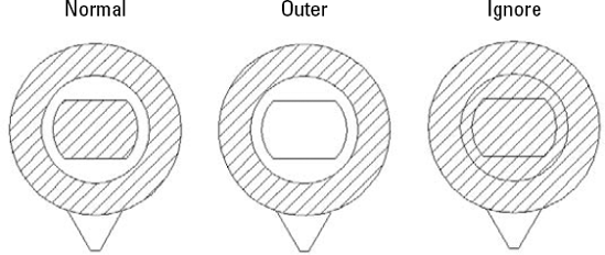
Three boundary styles affect how islands are hatched:
Normal. Hatches alternating areas so that the outer area is hatched, the next inner island is not hatched, the next inner island is hatched, and so on.
Outer. Hatches only the outer area and does not hatch any inner islands.
Ignore. Ignores islands and hatches everything from the outside in.
Figure 16.19 shows three copies of a nut hatched in the three styles. To hatch this model, I selected the entire model, except for the spout at the bottom, with a window.
When you pick points instead of selecting objects, you don't need to select the islands. Hatching detects islands by default. As soon as you pick points, the Remove Boundaries button becomes available, and you can select the islands to remove them from consideration if you want to hatch them. For example, if you remove all the islands shown in Figure 16.19, the result is the same as using the Ignore style, where everything inside the outside boundary is hatched.
When you pick points to determine the hatch boundary, the hatching process uses the same mechanism as the BOUNDARY command to temporarily create a boundary for hatching. Check Retain Boundaries in the Boundary Retention section of the expanded dialog box if you want to draw the boundary as an object, and specify whether you want it to be a region or a polyline. Otherwise, the boundary is discarded when the hatch is placed. For more information, see the discussion of the BOUNDARY command earlier in this chapter.
You can also specify a smaller boundary set than the objects that are visible on-screen. Use this when you're picking points and have such a complex drawing that the process of analyzing the visible objects takes a long time. To create a new boundary set, click the New button and specify a window in your drawing.
You can hatch areas that are not completely closed by using the Gap Tolerance feature. In the Tolerance text box, enter a value greater than the size of the gap. You can use values from 0 to 5,000. In order to hatch an unclosed area in this way, you need to pick points rather than choose objects. When you hatch an unclosed area, sometimes picking points is more successful; other times, selecting objects works best, so try both options. Either way, the Open Boundary Warning message opens. Click Yes to hatch the open boundary. Note that the hatch is not associative, which means that if you modify your almost closed area, you need to rehatch. Using this feature sets subsequent hatches as nonassociative, so be sure to recheck the Associative check box in the main part of the dialog box.
You can fine-tune how a hatch inherits properties, specifically the hatch's origin. Choose to use the current origin setting (from the left side of the dialog box) or use the setting of the source hatch.
After you have spent the time creating a hatch, you may want to use that hatch in other drawings. You can open a PAT (hatch pattern) file from the DesignCenter, preview its hatch patterns, and drag any hatch pattern into any closed object in your current drawing. Here's how to drag a hatch pattern from the DesignCenter:
Choose View tab
Use the Tree view to navigate to the folder that contains your
acad.pat, acadlt.pat, or other.patfile. If necessary, click the Desktop button and navigate from there.Note
To find the location of your
.patfiles, choose Application ButtonDouble-click the folder and select a hatch pattern (
.pat) file. A preview of all the hatch patterns appears in the right pane.From the right pane of the DesignCenter, drag the hatch pattern that you want onto a closed object in your drawing (or an unclosed object with the gap tolerance value greater than the gap). If you need more options, right-click the pattern as you drag, then choose BHATCH from the shortcut menu to open the Hatch and Gradient dialog box, and then specify the hatch parameters in the usual way.
You can drag a hatch pattern to a tool palette to create a hatch with the properties of the hatch in your drawing. Then you can drag that hatch tool onto any closed area in your drawing. The hatch automatically fills the area with the same properties. For more on tool palettes, see Chapter 26.
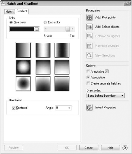
Gradients are fills that gradually change from dark to light or from one color to another. You can use gradients to create presentation-quality illustrations without rendering. You can also use gradients as a substitute for shading because they offer more flexible options.
Note
AutoCAD LT doesn't offer the gradient feature.
To create a gradient:

Choose One Color or Two Color.
If you choose One Color, click the ellipsis button to the right of the color swatch to open the Select Color dialog box, where you can choose the color you want. (For instructions on using this dialog box, see Chapter 11.) Then use the Shade/Tint slider to choose whether you want the gradient to range lighter or darker. You see the result in the gradient swatches below the slider.
If you choose Two Color, you see two color swatches. Click each Ellipsis button and choose a color.
Choose one of the nine gradient styles.
If you want the gradient to be symmetrical, check the Centered check box. To create a gradient that isn't symmetrical, uncheck the Centered check box. When you uncheck the Centered check box, the gradient focus moves up and to the left. (You can change this location by changing the angle, as explained in the next step.)
From the Angle drop-down list, choose an angle. If your gradient is centered, the gradient rotates around its center and remains symmetrical. If your gradient is not centered, the gradient rotates around the edges. Watch the gradient style tiles to see the results. You can type an angle that is not on the list.
Choose Add: Pick Points to pick a location inside a closed area or choose Add: Select Objects to select closed objects, as explained in the section "Determining the hatch boundary." (The other options are the same as for hatches.) In your drawing, specify the area that you want to hatch, and then end selection to return to the dialog box.
To preview the gradient, click Preview. To return to the dialog box, press Esc.
Click OK to finalize the gradient.
You can use the Gap Tolerance feature to fill an almost-enclosed area with a gradient. For more information, see the discussion on hatches in the "Other advanced options" section earlier in this chapter.
See Figure 16.21 for an example of some gradient fills. You could turn off the boundary's layer for a more realistic look.
To edit a hatch pattern, including a solid or gradient, choose Home tab
The Hatch Edit dialog box is exactly the same as the Hatch and Gradient dialog box, except that not all the options are available. You can use this dialog box to change any of the hatch properties. You can change the boundary style on the expanded area of the dialog box. You can also preview the hatch. After you make your changes, click OK to return to your drawing.
Because hatches are associative (unless you explode them or choose to create them as nonassociative), when you edit their boundaries, they adjust to fit the new boundary. However, if the new boundary is no longer closed, the hatch may lose its associativity, and you see the Hatch boundary associativity removed warning message.
Note
If a hatch has lost its associativity to a boundary, you can still alter its shape by using its grips to edit the hatch. Select the nonassociative hatch, select the grip, and drag.
By default, object snaps don't work with hatch lines. This prevents you from accidentally drawing to a hatch line instead of a nearby object. If you want to snap to hatch lines, choose Application Button
Tip
You can obtain the area of a hatch in the Properties palette. Select a hatch and open the Properties palette. Look for the Area item in the Geometry section.
You can also re-create the boundary of any hatch as a polyline or region. Edit the hatch and choose Recreate Boundary in the Edit Hatch dialog box. You can use this feature to create a boundary for a hatch if you have deleted it.
You can also edit a gradient (AutoCAD only) in the Properties palette; use the items in the Pattern section. You can change the colors, angle, type, and whether it is centered.
You may find it difficult to select solid fill hatches. In some locations, you can pick the solid hatch, while at other points, you get the Other corner: prompt, meaning that no object was found. If necessary, try a crossing window at the edge of the hatch. This always selects the solid hatch but also selects the boundary. Hatches have a grip at their center. If you can find the grip and include it in the window, you can easily select the solid hatch. When the hatch highlights as you hover the mouse over it, you can pick to select it.
Tip
You can trim hatches. Choose any object that crosses the hatch as the cutting edge and then select the hatch (on the side that you want to trim) as the object to trim. Chapter 10 covers trimming objects.
Note
The drawing used in the following exercise on creating and editing hatches, ab16-f.dwg, is in the Drawings folder on the DVD.
STEPS: Creating and Editing Hatches
Open
ab16-f.dwgfrom your DVD.Save the file as
ab16-06.dwgin yourAutoCAD Biblefolder.
You're now back in your drawing. Pick the two large circles, as shown in Figure 16.22. Right-click and choose Preview. Press Esc to return to the dialog box. Click OK to create the hatch and end the BHATCH command.
Again start the BHATCH command. From the Type drop-down list, choose User defined. Set the angle to 135 and the spacing to 0.05.
Choose Add: Pick Points. In your drawing, pick points
Click the circumference of the left large circle. (If necessary, zoom in to avoid selecting the hatching.) Pick the top grip to make it hot. At the
Specify stretch point or [Base Point/Copy/Undo/eXit]:prompt, type .35Click one of the hatches at the top of the model and choose Home tab
Save your drawing.
The SOLID command creates solidly filled 2D areas. (It is not directly related to 3D solids.) In general, BHATCH is much more flexible. Although the SOLID command is a 2D command, it's sometimes used in 3D drawing. When you create a 2D solid and give it thickness, it creates surfaces with tops and bottoms. I cover using thickness in Chapter 21.
SOLID creates straight-edged shapes. If FILLMODE is on, AutoCAD or AutoCAD LT fills in the shape with a solid fill. (That's why it's called SOLID.)
To draw a solid, type solid
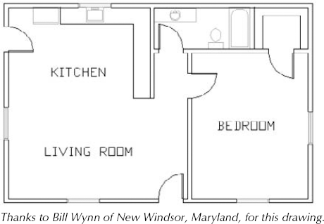
Multilines are sets of parallel lines that you draw with one command. You can specify how far apart they are, and each line can have its own color and linetype. Multilines are common in architectural plans where you need to draw an inner and outer wall. (I cover a 3D version, polysolids, in Chapter 24.) To draw a multiline, you first define, save, and load a multiline style. Then you can use the multiline style to draw multilines. There is a separate command for editing multilines. Figure 16.23 shows a floor plan for an apartment drawn using multilines.
Note
AutoCAD LT doesn't have the Multiline feature but has a similar feature called Dlines. I cover Dlines in the section "Creating Dlines in AutoCAD LT."
The first step in drawing multilines is to design the multiline style. To create a multiline style, type mlstyle
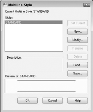
Like text styles and dimension styles, multiline styles group a set of properties under one name. The default multiline style, called Standard, defines two lines, one unit apart. Multiline styles have two parts: element properties and multiline properties. The element properties define each individual line element. The multiline properties define properties that apply to the multiline as a whole.
To start defining the multiline style, click New. In the Create New Multiline Style dialog box, type a name and click Continue. The New Multiline Style dialog box opens, as shown in Figure 16.25.
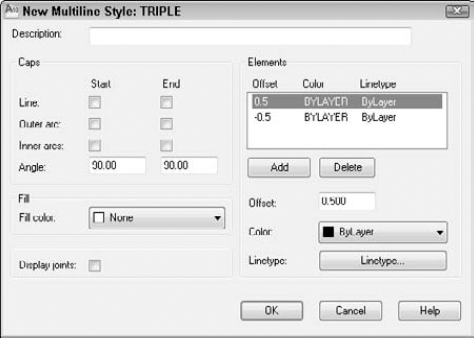
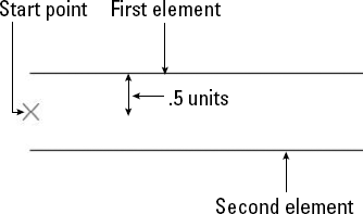
The Elements section lists the current elements of the multiline. Elements are the lines that make up the multiline. The offset defines the distance of the line from the start point when you start to draw. An offset of zero places the line on the start point. As you can see, the Standard multiline style has two elements, each 0.5 units from the start point. Figure 16.26 shows the Standard multiline style as it appears in relation to the start point that you pick.
Note
You can change the relationship of the start point and the element lines with the Justification option, as explained later in the "Drawing multilines" section.
To define the element lines of a multiline style, follow these steps:
In the Elements section, highlight the first element. Even if you typed a new name for the multiline style, the elements listed are the same as the current multiline style.
Tip
When creating a new multiline style, first set as current the multiline style that is the most similar to the one that you want to create.
In the Offset box, type the offset value that you want. The offset should be zero if you want the line to appear on your pick points, a positive number (in units) if you want the line to appear above your pick points, and a negative number (in units) if you want the line to appear below your pick points. (This assumes the default of zero justification, explained later in this chapter.)
Tip
When defining the multiline style elements, think of the multiline as being drawn horizontally to the right to help you visualize what above and below mean.
Choose Color to choose a color for the line element.
Choose Linetype to choose a linetype for the line element.
Choose Add to add a new element, or choose Delete to delete a listed element.
To define the next element, select the second element in the Elements box and repeat Steps 2 through 5. Continue to define elements until you're done.
If you want, enter a description for the multiline style in the Description text box.
Click OK to return to the Multiline Style dialog box.
Note
A multiline style can have up to 16 elements. All 16 elements must be on the same layer, but you can vary the linetypes and colors.
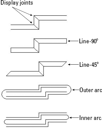
Use the left side of the New Multiline Style dialog box to set the overall properties of the multiline. Caps cross the ends of multilines to close them. You can choose line or arc caps. Figure 16.27 shows the effects of all the possible choices in this box. You can also choose a color to add a solid fill to the multiline. To display a line at the junction of each line segment, check the Display Joints check box. After you make your choices, click OK to return to the Multiline Style dialog box.
Before you can use the multiline style, you must save it. AutoCAD saves multiline styles in a file with the MLN filename extension. After you click Save, the Save Multiline Style dialog box opens.
In general, you can save your multiline styles in the default file, which is acad.mln. Click Save to return to the Multiline Style dialog box.
As with linetypes, you must load multiline styles before you can use them. Choose Load to open the Load Multiline Styles dialog box. Choose the style that you created from the list and click OK. You return to the Multiline Styles dialog box. You're now ready to use the multiline style. Click OK to return to your drawing.
You can also use the Multiline Style dialog box to rename multiline styles and make another multiline style current.
Note
The drawing used in the following exercise on creating a multiline style, ab16-g.dwg, is in the Drawings folder on the DVD.
STEPS: Creating a Multiline Style
Open
ab16-g.dwgfrom your DVD.Save the file as
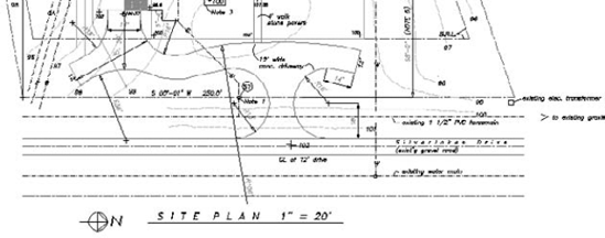
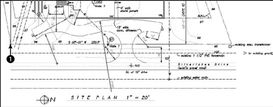
ab16-07.dwgin yourAutoCAD Biblefolder. This is a site plan, as shown in Figure 16.28.Type mlstyle
In the Elements section of the dialog box, the top element should be highlighted. Change the offset to 0, the color to black (it may list as white), and the linetype to DASHDOT.
Highlight the second element. Change the offset to −132 (11' × 12″), the color to magenta, and the linetype to continuous.
Click Add. Change the offset to −180 (15' × 12″), the color to red, and the linetype to center.
Click Add. Change the offset to −228 (19' × 12″), the color to magenta, and the linetype to continuous.
Click Add. Change the offset to −360 (30' × 12″), the color to black, and the linetype to dashdot.
Click Add. Change the offset to −480 (40' × 12″), the color to red, and the linetype to center.
Click OK. In the Multiline Style dialog box, click Save.
Warning
If you are using someone else's computer, check with the owner before saving the linestyle to
acad.mln. You can't do any damage, but the owner may not want to have your multiline style there. You can change the name in the File Name text box to something else, such asmy_mls.mln.In the Save Multiline Style dialog box, you should see
acad.mlnin the File Name text box. You can also type a new MLN filename. Choose Save.With the new multiline style selected, choose Set Current, and click OK to return to your drawing.
Save your drawing. If you're continuing on to the next exercise, keep the drawing open.
Defining a multiline style is the hard part. As soon as the style is defined, saved, loaded, and made current, you can draw with it. You may find that you need some practice to get the hang of it because you're drawing more than one line at once. To draw a multiline, type mline
Justification. You can choose Zero, Top, or Bottom.
Zero places the element that has a zero offset in the multiline definition at the pick point. You do not need to have a line at zero offset, as is the case with the Standard multiline style. The top example in Figure 16.29 shows the Standard multiline style with zero justification.
Top places the line with the highest positive offset at the pick point. The middle example in Figure 16.29 shows the Standard multiline style with top justification.
Bottom places the line with the highest negative offset at the pick point. The bottom example in Figure 16.29 shows the Standard multiline style with bottom justification.
Scale. Multiplies the offset values in the multiline definition by the scale. The Standard multiline style places two lines 1 unit apart. A scale of 6 would place them 6 units apart.
Style. Enables you to specify the current multiline style. Type ?
As you draw a multiline, whenever you create a corner by changing direction, the command creates a clean corner.
STEPS: Drawing Multilines
Continue from the previous exercise. (If you didn't do the previous exercise, you should do it to create the multiline style.) Set a running object snap for Intersection. Turn on Ortho Mode.
Type mline
Current settings: Justification = Top, Scale = 1.00, Style = SITEPLAN
At the
Specify start point or [Justification/Scale/STyle]:prompt, press Shift+right-click and choose the From object snap. At theBase point:prompt, chooseAt the
Specify next point:prompt, move the cursor to the right and type 255'
No matter how many segments it contains, the entire multiline is one object. Many editing commands simply do not work with multilines. Table 16.1 shows the editing commands and whether they work with multilines.
Table 16.1. Using Editing Commands with Multilines
Command | Usable with Multilines | Command | Usable with Multilines |
|---|---|---|---|
ARRAY | Yes | LENGTHEN | No |
BREAK | No | MIRROR | Yes |
CHAMFER | No | MOVE | Yes |
COPY | Yes | ROTATE | Yes |
EXPLODE | Yes | SCALE | Yes |
EXTEND | Yes | STRETCH | Yes |
FILLET | No | TRIM | Yes |
You can use grips to stretch, move, copy, mirror, and rotate multilines.
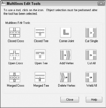
To edit multilines, you use the MLEDIT command. To start MLEDIT, type mledit
This dialog box enables you to edit multiline intersections and corners. You can also add or delete a vertex. Click one of the images, and its name appears at the bottom of the dialog box.
The first column manages crossing intersections. To edit a crossing intersection, choose one of the tiles in the first column and click OK. The command prompts you to pick a first multiline and then a second multiline. MLEDIT always cuts the first multiline that you pick. The second one may be cut if it is called for by the edit type.
Note
Although the command prompts you to pick two multilines, they can actually be two parts of the same multiline.
The second column manages T-shaped intersections. To edit a crossing intersection, choose one of the tiles in the second column and click OK. The command prompts you to pick a first multiline and then a second multiline. MLEDIT always cuts the first multiline that you pick. The second one may be cut if called for by the edit type and depending on the shape of the multiline.
The third column manages corners and vertices. The top tile creates a corner. The second tile adds a vertex, and the third deletes a vertex. Choose the edit that you want and click OK. The command prompts you to select a multiline. Be careful — you must pick the point where you want to add or delete the vertex. To see the current vertices, pick the multiline with no command active to see the grips.
The last column of the dialog box makes cuts through multilines and welds them back together again. Here's how to use these options:
Use the top tile to make a cut through one element of a multiline.
Use the middle tile to cut through all the elements of a multiline.
In both cases, you get a prompt to select a multiline and then a second point. Be careful — the point that you use to select the multiline is the first point of the cut. For a single cut, the pick point of the multiline also determines which element the command cuts.
Use the bottom tile to remove the cuts. Removing cuts is called welding.
For all these editing tools, you get prompts for further edits. Press Enter to end selection.
You can also move vertices by using grips with the Stretch option.
Note
An old command, TRACE, draws lines with width. Usually you can use polylines or multilines instead to create the same effect.
Multiline styles are stored with the drawing, so you can update and view them even if the multiline style file containing the multiline definition is not available.
Dlines are the AutoCAD LT equivalent of multilines. AutoCAD does not include dlines. Dlines (double lines) create line segments and arcs that are individual objects. The double lines and arcs have nicely finished corners and ends. You can specify the width between the lines, offset the lines from your pick points, and cap the lines with a simple square cap.
To create a dline, type dline
Break. Breaks the dline when it crosses other double lines, single lines, or arcs.
Caps. Places a square cap at the start or end of the double line or at both the start and end. Otherwise, use the None suboption.
Dragline. Offsets the double line from your pick points. A positive value for this option offsets to the right, and a negative value offsets to the left of your pick points. By default, the double line is centered on either side of your pick points. You can also choose to use the Left or Right suboptions to align the left or right line with your pick points.
Snap. Ends a double line whenever you use an object snap.
Width. Specifies the distance between the double lines.
After you specify the first point, the prompt expands to give you three more options:
Arc. Creates double arcs. (You can't easily do this in AutoCAD!) You have suboptions that are similar to the ARC command options, including a Line option to return to drawing line segments.
CLose. Draws a double line from the last point back to the first point.
Undo. Undoes the last line segment or arc.
Because dlines are individual lines and arcs, there are no special editing tools and they are easy to edit.
The SKETCH command enables you to draw freehand. Freehand drawing is useful for contour lines in architectural or civil engineering drawings, for illustrative effects, and for when you're feeling artistic. Although you may get best results if you have a digitizer and a stylus pen, you can sketch with a mouse or puck as well. Figure 16.32 shows some contour lines created with SKETCH.
SKETCH can create lines or polylines. Polylines are probably easier to work with if you need to edit the sketch later; you can use the PEDIT command. To specify whether SKETCH creates lines or polylines, set the SKPOLY system variable. A value of 0 creates lines, and a value of 1 creates polylines.
Start the SKETCH command by typing sketch
Record increment <0.1000>: Press Enter or type a new increment.
Sketch. Pen eXit Quit Record Erase Connect.
Type the record increment, which is the length of the line or polyline segment that you want to create. If the increment is too big, small movements do not create a segment at all, and the sketch line appears jagged instead of smooth. However, you need to take into account the scale of your drawing and your zoom factor. You should also turn off Ortho Mode and Snap Mode if they're on.
The pick button is equivalent to typing p, and toggles the pen up and down. Follow these steps to start sketching:
Place the cursor where you want to start drawing.
Press the pick button. The prompt responds with the
<Pen down>message. You can now draw.Without holding down the pick button, move the mouse or stylus to create the shape that you want. SKETCH creates a temporary green line.
After you finish, click the pick button again to see the
<Pen up>message.Move the mouse to the starting point of your next line or polyline. Continue in this manner until you finish sketching.
Type r to record the sketch. The prompt tells you what you created. The sketch changes to the color of the current layer and becomes permanent.
Type x to exit Sketch mode.
Quit. Quits Sketch mode without saving your sketch. The temporary line disappears.
Erase. Erases temporary lines.
Connect. Enables you to continue drawing from the end of the last sketch. Use this when the pen is up. Type c and move to the endpoint of the last temporary sketch.
. (Period). Enables you to draw straight-line segments from the endpoint of the last sketch. While the pen is up, type a period to add a line segment from the last endpoint to your current cursor position.
Note
The drawing used in the following exercise on sketching, ab16-h.dwg, is in the Drawings folder on the DVD.
STEPS: Sketching
Open
ab16-h.dwgfrom your DVD.Save the file as
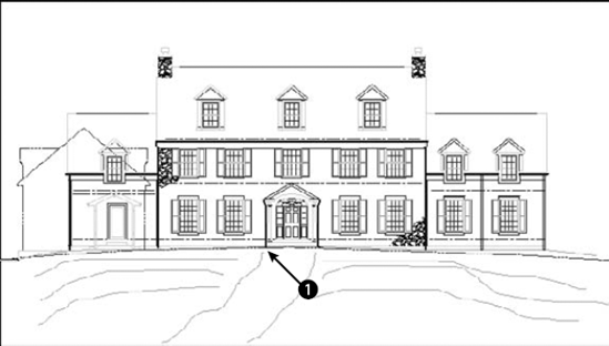
ab16-08.dwgin yourAutoCAD Biblefolder. It shows the front elevation of a house. You'll add the sketched path and contours, as shown in Figure 16.33.Type skpoly
Type sketch
At the
Sketch. Pen eXit Quit Record Erase Connect .prompt, move the cursor toUse the same technique to draw the other lines in Figure 16.33. If you make a mistake, type q
After you're done, type r to record the lines.
Type x to end the SKETCH command.
Save your drawing.
In Chapter 3, I explained that you can use a digitizer to execute commands. One important use for a digitizer is to copy paper drawings into your drawing. Many companies have used this technique to copy old drawings that were drafted by hand so that they could be edited electronically. Digitizing can also be used to copy artwork and logos into a drawing.
To digitize a paper drawing, you use a special digitizing mode that turns the entire digitizer into a drawing tablet. To start the TABLET command, type tablet
If you've been using the digitizer to execute commands, you need to reconfigure it to eliminate the command areas and enlarge the drawing area. Use the Configure option of the TABLET command and reconfigure the digitizer for 0 tablet menus. Respecify the screen pointing area so that the fixed screen pointing area covers the entire digitizing area.
Attach the paper drawing securely to the digitizer so that it won't move as you work.
To set up the digitizing mode, start the TABLET command and choose the Calibrate option. The option prompts you to pick two points on the paper drawing and specify which coordinates they represent. To do this, you need to mark two points on the paper drawing; take out a ruler and measure their distance. If the drawing has a titleblock, two corners of the titleblock are distinctive points to mark and measure. If the drawing is drawn to a scale — and it probably is — the coordinates you type should be the distance in real life, not the measurement. In other words, if the two horizontal points are 1 inch apart and 1 inch represents 48 inches (a scale of 1 = 48), you could enter 0,0 for the first point and 48,0 for the second point. However, it is usually useful to choose points over a wider area of your drawing. You can calibrate more than two points if you want.
Note
If your drawing is distorted or uses a perspective view that you want to straighten out, you can calibrate additional points and choose either Affine or Projective calibration to account for the distortion. Affine calibration requires at least three points and scales the X and Y axes separately. Projective calibration requires at least four points and stretches the coordinates to adjust for the perspective view.
After you finish specifying calibration points and coordinates, press Enter. Now your entire tablet can be used only for picking points. You can press F12 to use the ribbon (or a menu or toolbar) and press F12 again to return to picking points, or type commands on the command line. Choose the command that you need and pick points along the paper drawing. After you're done, turn off Tablet mode and do any necessary editing and cleanup.
Note
You can turn Tablet mode on and off by starting the TABLET command and choosing the On and Off options. Tablet calibration settings are lost when you close the drawing session.
In this exercise, you practice digitizing drawings. If you have a digitizer, try this exercise. Otherwise, skip it.
STEPS: Digitizing Drawings
Start a new drawing using
acad.dwtoracadlt.dwtas your template.Save the file as
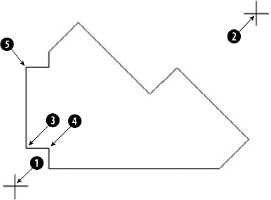
ab16-09.dwgin yourAutoCAD Biblefolder. This is a sheet-metal template, as shown in Figure 16.34.Make a photocopy of Figure 16.34 and tape it to the active area of your digitizer.
Type tablet
Digitize point #1:
Pickin Figure 16.34. Enter coordinates for point #1:0,0Digitize point #2:Pick. Enter coordinates for point #2:7,5Digitize point #3 (or RETURN to end):Type tablet
Type line
In Figure 16.34, pick

After you reach

Type tablet
Save your drawing.
Several types of complex objects add greatly to the capabilities of AutoCAD and AutoCAD LT. In this chapter, you read about:
Using polylines to combine lines, segments, and arcs of any width into one object
Utilizing splines to mathematically calculate curves, fit to points that you specify
Using regions, which are two-dimensional surfaces
Creating regions or polylines from complex areas by using the BOUNDARY command
Filling in an area with lines, a solid fill, or a gradient (AutoCAD only) with the hatch feature
Drawing complex parallel lines at one time with multilines (AutoCAD only), and drawing double lines with AutoCAD LT
Drawing freehand by using the SKETCH command
Using a digitizer in Tablet mode, when you need to copy a paper drawing into AutoCAD or AutoCAD LT
In the next chapter, I explain how to lay out and plot a drawing.