
This chapter completes the discussion, started in the preceding chapter, of geometric editing commands — covering the more complex commands used to refine the details of your drawing. These commands enable you to copy, move, resize, break, and cover objects, as well as construct corners. I also discuss grips, which make it easy to move, mirror, rotate, scale, and stretch objects, and I explain how to use the Quick Properties panel and the Properties palette to edit objects. I end the chapter with a discussion of three ways to control the selection of objects — groups, filters, and the Quick Select feature.
Note
Although you can use the editing tools that I describe in this chapter in a 3D environment, this chapter assumes that you are working in a 2D environment, using the default 2D Drafting & Annotation workspace. (AutoCAD LT doesn't offer a 3D environment.) To make sure that you're in a 2D environment, set the workspace to 2D Drafting & Annotation (from the Workspace Switching pop-up list on the status bar) and set the visual style to 2D Wireframe (type vscurrent and choose the 2D Wireframe option). If you still see the Z axis on the UCS icon, choose View tab
Three commands enable you to copy objects in very specific ways. MIRROR creates a mirror image. ARRAY copies objects in a rectangular or circular pattern. OFFSET creates parallel objects. Although these commands make copies of objects, they produce a result that would be difficult or impossible to produce simply by using the COPY command. The ALIGN and 3DALIGN commands move objects by aligning them with other objects in the drawing.
Many drawings have symmetrical elements. Often, especially in mechanical drawings, you can create one half or one quarter of a model and complete it simply by mirroring what you have drawn.
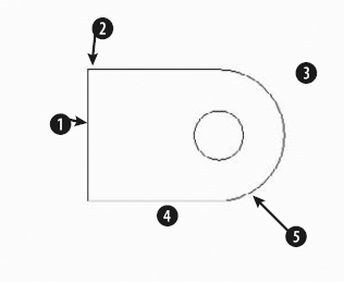
The command prompts you for the first and second points of the mirror line. This is an imaginary line across which the command creates the mirrored object. The length of the line is irrelevant — only its start point and direction are important.
Tip
Most mirror lines are orthogonal. Therefore, after you specify the first mirror point, you can turn on Ortho Mode and move the mouse in the direction of the second point. You can then quickly pick the second point. Polar tracking can also easily guide you to specify an orthogonal mirror line.
The command then asks if you want to erase the source objects. The source objects are the objects you have selected to mirror. If you want to keep them, type n
Note
The drawing used in the following exercise on mirroring objects, ab07-02.dwg, is in the Results folder on the DVD.
STEPS: Mirroring Objects
Open
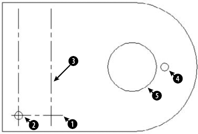
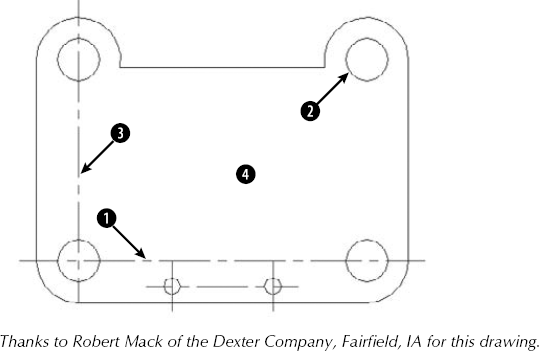
ab07-02.dwgfrom theResultsfolder of the DVD. If you completed the exercise on arcs in Chapter 7, you can open this drawing from yourAutoCAD Biblefolder.Save the file as
ab10-01.dwgin yourAutoCAD Biblefolder. Make sure Object Snap mode is on. Set a running object snap for Intersection only.Choose Home tab


At the
Specify first point of mirror line:prompt, pick intersection
The command prompts
Erase source objects? [Yes/No] <N>:Press Enter to accept the default, No.Start the MIRROR command again. At the
Select objects:prompt, type p
At the
Specify first point of mirror line:prompt, pick intersection
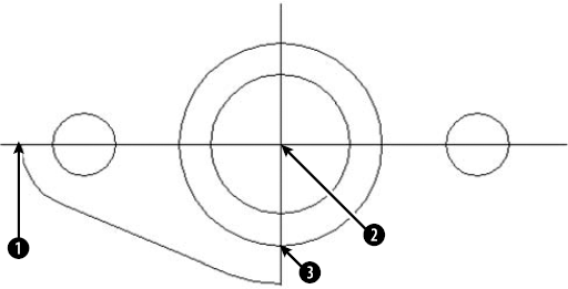
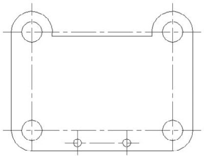
The command completes the mounting plate. Save your drawing. It should look like Figure 10.2.
The ARRAY command creates a rectangular or polar (circular) pattern by copying the object(s) you select as many times as you specify. The ARRAY command is a powerful drawing tool. It can quickly create large numbers of objects, thus saving a huge amount of time and effort.
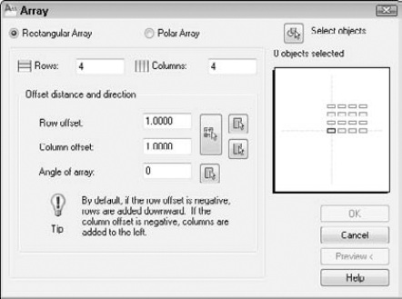
A rectangular array creates a grid of rows and columns of one or more objects. Figure 10.3 shows an example of a rectangular array. To create a rectangular array, follow these steps:
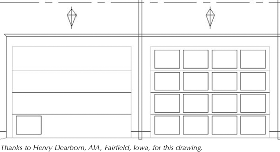
Figure 10.3. The garage door was drawn with one panel, as shown on the left side. A rectangular array created the rest of the door panels, as shown on the right.

Click Rectangular Array at the upper-left corner of the dialog box (if it is not already selected).
If you've already selected one or more objects, the dialog box indicates the number of selected objects. If you haven't selected any object, click Select Objects to return to your drawing and select objects. Press Enter to end object selection and return to the dialog box.
In the Rows and Columns text boxes, type the total number of rows and columns that you want.
Type the distance you want between the rows in the Row Offset text box, and type the distance you want between the columns in the Column Offset text box. If you want to specify the offsets by picking points on your screen, click the Pick button next to the Row Offset or Column Offset text box, or use the longer Pick button spanning both text boxes to pick diagonal points and specify both offsets at once.
If you want to change the angle of the array, type an angle in the Angle of Array text box. The preview panel displays the results of this value. To specify the angle by picking, click the Pick Angle of Array button.
To preview the array, click Preview. Click anywhere (pick) or press Esc to return to the Array dialog box if you want to make changes; otherwise, right-click to accept the array and end the command. If you change the snap angle or the UCS (as explained in Chapter 8), AutoCAD and AutoCAD LT create the rectangular array at the angle of the snap or UCS.
A polar array creates copies of one or more objects arrayed in a circle around a center point. An example of a polar array is shown in Figure 10.5.
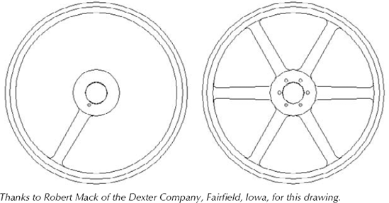
Figure 10.5. The pulley was drawn with one spoke, as shown on the left. A polar array created the additional spokes.
To create a polar array, follow these steps:

Click Polar Array at the top of the dialog box (if it is not already selected).
If you've already selected one or more objects, the dialog box indicates the number of selected objects. If you haven't selected any objects, click Select Objects to return to your drawing and select objects. Press Enter to end object selection and return to the dialog box.
Specify the center point by typing X and Y coordinates, or click the Pick Center Point button. If you selected an object first, check that the center point displayed is what you want.
Select the two items that you want to specify from the Method drop-down list. You can choose any two from the three choices:
Total Number of Items. Sets the total number of items in the resulting array, including the one that you are arraying.
Angle to Fill. Sets the number of degrees that the polar array covers. For example, to array around half of a circle, specify 180°.
Angle Between Items. Specifies the number of degrees between each item in the polar array.
Complete the values of the two items that you specified. You can click the buttons to pick the angle to fill or the angle between items on the screen.
Check the Rotate Items as Copied check box to rotate the objects that you are arraying. Uncheck the box to leave them unrotated.
Click Preview to preview the array. Click anywhere (pick) or press Esc to return to the Array dialog box if you want to make changes; otherwise, right-click to accept the array and end the command.
You can specify which point on the last object selected that AutoCAD or AutoCAD LT uses to array the objects. The command makes a calculation of the distance from the center point of the array to a base point on the last object selected. Otherwise, the command uses a default point based on the type of object selected. Table 10.1 lists the default base points. If you are arraying more than one object, you may not obtain the result you want without specifying the base point. Even for one object, you may want to change the base point that is used.
To specify the base point, click the More button at the bottom of the dialog box. The dialog box opens up to display the Object Base Point section. Uncheck Set to Object's Default. You can then either type in coordinates or, more likely, click the Pick Base Point button and use an object snap to pick the desired point on an object. The preview box adjusts according to your choice, but because the preview only shows rectangles in the place of your object, the display may not be very helpful. You can click the Preview button to preview the result in your drawing.
Note
You can use the Express Tools COPYM command to enhance your copying options. Type copym
Table 10.1. Object Base Points for Arrays
Type of Object | Default Base Point |
|---|---|
Arc, circle, or ellipse | Center point |
Polygon or rectangle | First corner |
Line, polyline (2D or 3D), ray, spline, or donut | Starting point |
Text (single-line or paragraph), block | Insertion point |
Construction line (xline) | Midpoint |
Region | Grip point |
Note
The drawing used in the following exercise on arraying objects, ab10-a.dwg, is in the Drawings folder on the DVD.
STEPS: Arraying Objects
Open
ab10-a.dwgfrom the DVD.Save the file as
ab10-02.dwgin yourAutoCAD Biblefolder. It looks like Figure 10.6. Object Snap mode should be on. Set Center and Intersection running object snaps.
Click the Select Objects button of the Array dialog box. In the drawing, pick the horizontal centerline
Make sure that Rectangular Array is selected at the top of the dialog box.
In the Rows text box, type 4. In the Columns text box, type 1.
In the Row Offset text box, type 1. (You don't need to specify the column offset because you are creating only one column.)
Click Preview. You should see a total of four horizontal lines, as shown in Figure 10.7. Right-click to accept the array. (If you don't see the four lines, click anywhere in the drawing area and recheck the settings in the Array dialog box.)
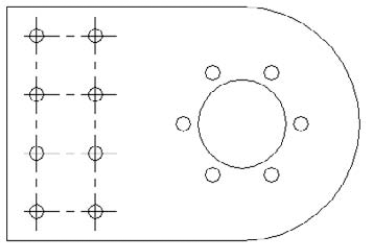
To add the holes to the pattern, again start the ARRAY command.
Click the Select Objects button in the Array dialog box. In the drawing, pick circle
Back in the Array dialog box, type 4 in the Rows text box and type 2 in the Columns text box.
Click the Pick Both Offsets button. In the drawing, pick the center of circle
Click Preview to preview the array. If the circles look like Figure 10.7, right-click. Otherwise, click in the drawing area or press Esc and check your settings. After you're done, the command arrays the holes to fit the centerlines.
To create a six-hole bolt circle, pick hole

In the Array dialog box, choose Polar Array.
Next to the Center Point text boxes, click the Pick Center Point button. In the drawing, pick the center of the large circle at

Make sure that the Method reads
″Total number of items & Angle to fill.″In the Total Number of Items text box, type 6. In the Angle to Fill text box, type 360.Click Preview to see the array. It should look like Figure 10.7. If it does, right-click. Otherwise, click in the drawing area or press Esc and recheck the settings in the Array dialog box. AutoCAD or AutoCAD LT completes the mounting bracket.
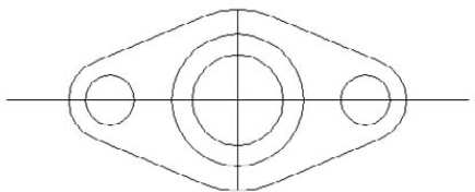
Save your drawing. It should look like Figure 10.7.
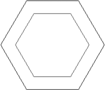
The OFFSET command creates lines or curves parallel to one existing object. The beauty of this command is apparent when you start to create complex objects, such as polylines, which are covered in Chapter 16. Polygons and rectangles are polylines, which means that all the line segments are one object. For example, using OFFSET, you can create concentric polygons in one step. Figure 10.8 shows two concentric polygons. The outside polygon was created with the POLYGON command, and the inside polygon was created by using OFFSET.
The command responds with the following list of settings and prompt:
Current settings: Erase source=No  Layer=Source  OFFSETGAPTYPE=0
Specify offset distance or [Through/Erase/Layer] <Through>:
The settings show how the OFFSET command's options will function. Set the Erase option to Yes to erase the selected object and leave only the offset. Use the Layer option to specify if you want the new object to be on the same layer as the source object or on the current layer.
Note
The OFFSETGAPTYPE system variable determines what the command does to close gaps when you offset closed polylines. By default (a value of 0), AutoCAD extends the polyline segments. A value of 1 fills the gaps with arcs, and a value of 2 fills the gaps with chamfered corners. (I cover chamfers later in this chapter.)
The OFFSET command offers two ways to specify the offset:
If you type an offset distance, the command responds with the
Select object to offset or [Exit/Undo] <Exit>:prompt. You can select one object. Then theSpecify point on side to offset or [Exit/Multiple/Undo] <Exit>:prompt appears. Pick a point to indicate on which side of the object you want to create the offset copy. The command creates the offset and continues to show theSelect object to offset or [Exit/Undo] <Exit>:prompt so that you can offset other objects by using the same offset distance. Press Enter to exit the command.If you want to indicate a through point (a point that the offset passes through, such as an object snap on another object), type t
Use the Undo option if you don't like the result of the offset. After you offset an object, the prompt repeats so that you can offset additional objects. Press Enter to end the command.
Note
The drawing used in the following exercise on using the OFFSET command, ab10-b.dwg, is in the Drawings folder on the DVD.
STEPS: Using the OFFSET Command
Open
ab10-b.dwgfrom the DVD.Save the file as
ab10-03.dwgin yourAutoCAD Biblefolder. It looks like Figure 10.9. Set a running object snap for Center, and turn on Object Snap mode.
Specify offset distance or [Through/Erase/Layer] <Through>:
orspecify the Through option if it does not appear as the default. Select object to offset or [Exit/Undo] <Exit>:Pickin Figure 10.9. Specify through point or [Exit/Multiple/Undo] <Exit>:Pick the center of. Select object to offset or [Exit/Undo] <Exit>:This action copies the centerline through the upper circles.
Repeat the OFFSET command. At the
Specify offset distance or [Through/Erase/Layer] <Through>:prompt, type 4-19/64Save your drawing. It should look like Figure 10.10.
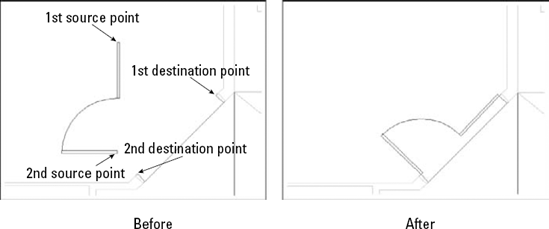
The ALIGN and 3DALIGN commands let you move and rotate an object or objects in one procedure. They are useful in both 2D and 3D environments. By specifying where selected points on an object move, you can align the object with other objects in your drawing, as shown in Figure 10.11. You can align in two ways:
ALIGN command. This command prompts you by point. You specify the first source point (on the object you're aligning), and then the first destination point (where that source point will end up). Then you specify the second set of source and destination points. For 3D, you go on to a third set. Finally, you can scale the selected object to match the destination points.
3DALIGN command. This command prompts you by object. You specify two or three points on the source object, and then the points at the destination location. As you specify destination points, you see the object move and align in real time. You cannot scale the object. See Chapter 24 for an exercise that uses the 3DALIGN command in 3D editing.
Note
The ALIGN command is now part of AutoCAD LT.
Aligning requires several steps. Even so, it can save you time when you need to move and rotate at the same time, especially if you don't know the rotation angle that you need.
Note
AutoCAD LT doesn't include the 3DALIGN command. Instead, you would need to use a combination of the MOVE and ROTATE commands. The Reference option of the ROTATE command would be helpful to align objects. I discuss the MOVE and ROTATE commands in Chapter 9.
The prompt asks for the first source point. Specify a point, usually an object snap on the object that you want to move.
The prompt asks for the first destination point. Specify the point where you want the first source point to end up.
The prompt asks for the second source point. If you press Enter, AutoCAD simply moves the selected objects. To continue to align, specify another point, usually another object snap on the object that you want to move.
The prompt asks for the second destination point. Specify the point where you want the second source point to end up.
The prompt asks for the third source point. You use this for 3D alignment, to specify how you want to rotate the object in the third dimension. For 2D alignment, press Enter to continue the command.
The prompt displays the
Scale objects based on alignment points? [Yes/No] <N>:prompt. If the distances between the source and destination points are not the same, type y if you want to scale the original object so that the source and destination points match exactly.
Then follow these steps:
The message,
Specify source plane and orientation, explains that you now need to specify the source points, which define the plane and orientation of the source object. The first prompt asks for the base point. Specify a point, usually an object snap on the object that you want to move. This point will match the first destination point. You can use the Copy option to make a copy of the object rather than move it. If you use the Continue option here, you only move the object.The prompt asks for the second point. Specify another point on the source object. This point will match the second destination point. Use the Continue option to start specifying destination points.
The prompt asks for the third point. In 3D models, you need the third point to specify the plane.
The message,
Specify destination plane and orientation, explains that you now need to specify the destination points for the base points you just specified. The prompt asks for the first destination point. Specify the point where you want the first base point to end up. As soon as you do this, the object moves to match the first base and destination points so that you can see how the object will look.The prompt asks for the second destination point. The second base point will match this point. If you press Enter at this point, the command aligns the object with the X axis of the current UCS.
The prompt asks for the third destination point. You use this for 3D alignment, to specify how you want to rotate the object in the third dimension. For 2D alignment, you can place the cursor on either side of the aligning line you specified, to mirror the object in either direction. When you see the direction that you want, press Enter to end the command and align the object.
The following exercise uses the ALIGN command to align objects.
Note
The drawing used in the following exercise on aligning objects in two dimensions, ab10-c.dwg, is in the Drawings folder on the DVD.
STEPS: Aligning Objects in Two Dimensions
Open
ab10-c.dwgfrom the DVD.Save the file as
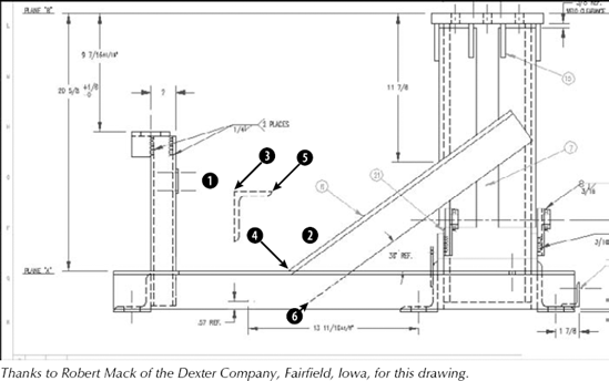
ab10-04.dwgin yourAutoCAD Biblefolder. It looks like Figure 10.12. Set a running object snap for Endpoint.
Select objects:
Select the horizontal angle by using a window, picking nearand then.Press Enter to end object selection. This angle needs to be aligned with the long, diagonal support angle. Specify first source point:Pick the endpoint at
in Figure 10.12. Specify first destination point:Pick the endpoint at. Specify second source point:Pick the endpoint at. Specify second destination point:Pick the endpoint at. Specify third source point or <continue>: Scale objects based on alignment points? [Yes/No] <N>:to accept the default No answer.
Save your drawing. It should look like Figure 10.13.
Four editing commands resize objects in specific ways. The TRIM and EXTEND commands change the endpoint of an object to meet another object. LENGTHEN lets you lengthen or shorten a line, polyline, arc, or elliptical arc. STRETCH is used to stretch (longer or shorter) a group of objects, letting you change their direction at the same time.
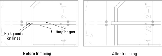
As you edit a drawing, you may find that lines or arcs that once perfectly met other objects now hang over. To trim an object, you must first specify the cutting edge, which defines the point at which to cut the object you want to trim. You define the cutting edge by selecting an object. You can select several cutting edges and several objects to trim at one time, as shown in Figure 10.14. When you select an object to trim, you must pick the object on the side that you want trimmed (not on the side that you want to remain). A common use for the TRIM command is to create intersections of walls in architectural floor plans.
Tip
While using the TRIM command, you can switch to extending objects by pressing the Shift key as you select objects to trim.
The object you want to trim does not have to actually intersect the cutting edge. You can trim an object to a cutting edge that would intersect the object if extended. This is called trimming to an implied intersection, an example of which is shown in Figure 10.15.
You can trim arcs, circles, ellipses, elliptical arcs, lines, polylines, xlines, rays, and splines. You can use polylines, arcs, circles, ellipses, elliptical arcs, lines, rays, regions, splines, text, or xlines as cutting edges. An object can be used as both a cutting edge and an object to be trimmed in the same trimming process. You can also trim to objects within blocks. (Chapter 18 covers blocks.)
You can trim to an actual or an implied intersection (an intersection that would exist if objects were extended):
If you want to trim to an actual intersection, at the
Select object to trim or shift-select to extend or [Fence/Crossing/Project/Edge/eRase/Undo]:prompt, select the objects that you want to trim. You can use the Fence option to draw lines that crisscross the objects that you want to trim. Use the Crossing option to select the objects with a crossing window. Be sure to pick each object between the cutting edge and the end you want to trim off. Press Enter to end object selection. This action trims the object(s).If you want to trim to an implied intersection, at the
Select object to trim or shift-select to extend or [Fence/Crossing/Project/Edge/eRase/Undo]:prompt, type e
Use the Undo option if the results of the trim are not what you want. You can then continue to select objects to trim. The eRase option lets you erase an object instead of trimming it, without leaving the TRIM command.
Note
The drawing used in the following exercise on trimming objects, ab10-d.dwg, is in the Drawings folder on the DVD.
STEPS: Trimming Objects
Open
ab10-d.dwgfrom the DVD.Save the file as
ab10-05.dwgin yourAutoCAD Biblefolder. It looks like Figure 10.16.
At the
Select object to trim or shift-select to extend or [Fence/Crossing/Project/Edge/eRase/Undo]:prompt, again pick lines atThe command trims the lines. Each line is used as the cutting edge for the other line.
Again start the TRIM command. At the
Select objects or <select all>:prompt, pick the line atAt the
Select object to trim or shift-select to extend or [Fence/Crossing/Project/Edge/eRase/Undo]:prompt, right-click and choose Edge. Then right-click and choose Extend at theEnter an implied edge extension mode [Extend/No extend] <Extend>:prompt.Pick the line at
Start the TRIM command again. At the
Select objects or <select all>:prompt, pickSave your drawing. It should look like Figure 10.17.
Note
Express Tools contains a command, EXTRIM, which is available on the command line. EXTRIM can use a polyline, line, circle, arc, ellipse, image, or text as the cutting line. You specify one side of the cutting object, and EXTRIM trims everything on that side. For example, if you choose a closed polyline and pick inside it, every object inside the polyline is trimmed.
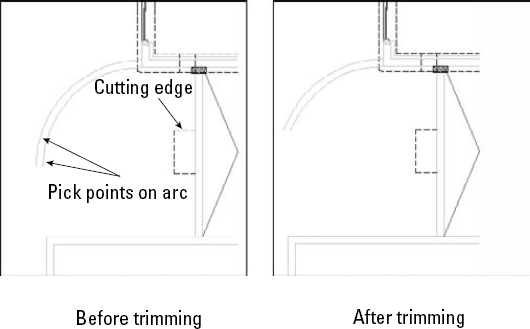
The EXTEND command has similar prompts to the TRIM command, but instead of trimming objects to a cutting edge, it extends them to a boundary edge (see Figure 10.18). As with TRIM, when you select an object to extend, you must pick the object on the side that you want extended (not on the side that you want left as is).
The object you want to extend does not have to actually intersect the boundary edge after its extension. You can extend an object to a boundary edge that would intersect the extended object if it were longer. This is called extending to an implied intersection, an example of which is shown in Figure 10.19.
You can extend arcs, elliptical arcs, lines, open polylines, and rays. You can use polylines, arcs, circles, ellipses, elliptical arcs, lines, rays, regions, splines, text, or xlines as boundary edges. An object can be used as both a boundary edge and an object to be extended in the same extending process.
Tip
While using the EXTEND command, you can switch to trimming objects by pressing the Shift key as you select objects to trim.
If the extension will result in an actual intersection, at the
Select object to extend or shift-select to trim or [Fence/Crossing/Project/Edge/Undo]:prompt, select objects to extend. You can use the Fence option to draw lines that crisscross the objects you want to extend. Use the Crossing option to select the objects with a crossing window. Be sure to pick each object at the end that you want to extend. Press Enter to end object selection and extend the object(s).If you want to extend to an implied intersection, at the prompt, right-click and choose Edge. The option responds with the
Enter an implied edge extension mode [Extend/No extend] <Extend>:prompt. Right-click and choose Extend. Then select the objects that you want to extend at theSelect object to extend or shift-select to trim or [Fence/Crossing/Project/Edge/Undo]:prompt. Be sure to pick each object at the end that you want to extend. Press Enter to end object selection and extend the object(s).
Use the Undo option if the results of the extension are not what you want. You can then continue to select objects to extend. You can use the Fence object selection method to select objects to extend the side of the object that the fence line crosses.
Note
The drawing used in the following exercise on extending objects, ab10-e.dwg, is in the Drawings folder on the DVD.
STEPS: Extending Objects
Open
ab10-e.dwgfrom the DVD.Save the file as
ab10-06.dwgin yourAutoCAD Biblefolder. It looks like Figure 10.20.
At the
Select object to extend or shift-select to trim or [Fence/Crossing/Project/Edge/Undo]:prompt, pick the line atRepeat the EXTEND command. At the
Select objects or <select all>:prompt, pick the lines atAt the
Select object to extend or shift-select to trim or [Fence/Crossing/Project/Edge/Undo]:prompt, right-click and choose Edge. Right-click and choose Extend at theExtend/No extend <No extend>:prompt.Pick lines
Save your drawing. It should look like Figure 10.21.
The LENGTHEN command both lengthens and shortens. It works on open objects, such as lines, arcs, and polylines, and also increases or decreases the included angle of arcs. AutoCAD and AutoCAD LT offer several ways of defining the new length or included angle. Use LENGTHEN if you want to lengthen or shorten an object when there is no available intersecting edge or boundary to use with TRIM or EXTEND.
In the LENGTHEN command, the length of an arc is measured along its circumference. Don't confuse this with the Length of Chord option of the ARC command, which refers to the length of a line stretched from one endpoint of the arc to the other endpoint.
Select object. This is the default. However, its purpose is to display the current measurements of the object. This can help you to decide how to define the final length or angle of the object. The current length is displayed at the command line, and the previous prompt is repeated.
DElta. Right-click and choose DElta. Delta means the change, or difference, between the current and new length or included angle. The option responds with the
Enter delta length or [Angle] <0.0000>.prompt. If you want to change an included angle, right-click and choose Angle. Then type the change in the included angle. Otherwise, simply type the change in the length of the object. A positive number increases the length or included angle. A negative number decreases the length or included angle.Percent. Right-click and choose Percent. At the
Enter percentage length <100.0000>:prompt, type in what percent of the original object you want the final object to be. Amounts over 100 lengthen the object. Amounts under 100 shorten the object. You cannot change an included angle by using this option.Total. Right-click and choose Total. At the
Specify total length or [Angle] <1.0000)>:prompt, you can either choose the Angle suboption, as described for the DElta option, or use the default total-length option. Either way, you enter the total angle or length you want.DYnamic. Right-click and choose DYnamic. This option lets you drag the endpoint of the object closest to where you picked it. You can use an object snap to specify the new endpoint.
After you've used an option to specify the length you want, you see the Select an object to change or [Undo]: prompt. Here you select the object you want to change. Be sure to pick the endpoint of the object for which you want to make the change.
The same prompt continues so that you can pick other objects by using the same length specifications. Choose Undo to undo the last change. Press Enter to end the command.
Note
The drawing used in the following exercise on lengthening and shortening objects, ab10-f.dwg, is in the Drawings folder on the DVD.
STEPS: Lengthening and Shortening Objects
Open
ab10-f.dwgfrom the DVD.Save the file as
ab10-07.dwgin yourAutoCAD Biblefolder. It is a capacitor symbol from an electrical schematic, as shown in Figure 10.22.
Select an object or [DElta/Percent/Total/DYnamic]:
Pick the line atin Figure 10.22. Current length: 0.200 Select an object or [DElta/Percent/Total/DYnamic]:Right-click and choose Delta. Enter delta length or [Angle] <0.000>:.07Select an object to change or [Undo]:Pick the line atin Figure 10.22. Select an object to change or [Undo]:This action lengthens the line.
Start the LENGTHEN command again and follow the prompts:
Select an object or [DElta/Percent/Total/DYnamic]:
Pick the arc atin Figure 10.22. Current length: 0.407, included angle: 150 Select an object or [DElta/Percent/Total/DYnamic]: Right-click and choose Total. Specify total length or [Angle] <1.000)>:Right-click and choose Angle. Specify total angle <57>:120Select an object to change or [Undo]:Pick the arc atin Figure 10.22. Select an object to change or [Undo]:This action shortens the arc.
Save your drawing. It should look like Figure 10.23.
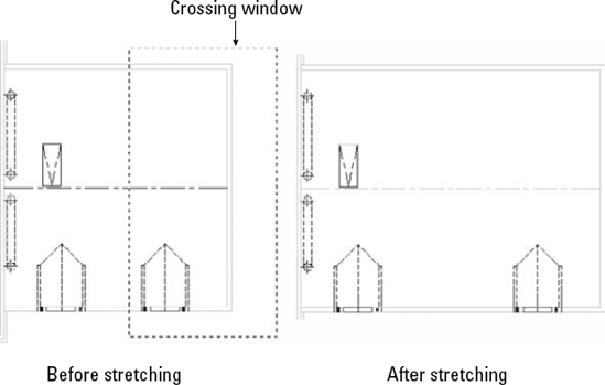
The STRETCH command is generally used to stretch groups of objects. For example, you can use this command to enlarge a room in a floor plan. You can also shrink objects. You can change not only the length of the objects but the angle as well. You use a crossing window to choose the objects to be stretched. All objects that cross the boundaries of the crossing window are stretched. All objects that lie entirely within the crossing window are merely moved. Successful stretching involves precise placement of the crossing window. Figure 10.24 shows the process of stretching a garage. Note that the walls that cross the boundaries of the crossing window are stretched. However, the dormer that is entirely within the crossing window is just moved. This maintains the integrity of the model.
You cannot stretch circles, text, or blocks. You can stretch arcs, although the results may not be what you expect.
The real power of the STRETCH command is in stretching a number of objects at once. However, you can also stretch one line. The results are similar to using the CHANGE command to change the endpoint of a line or to editing with grips (discussed later in this chapter).
The STRETCH command remembers the most recent displacement throughout a session. To stretch an object by the same displacement that you most recently used, press Enter at the Specify base point or [Displacement] <Displacement>: prompt. At the Specify displacement <2.0000, 3.0000, 0.0000>: prompt, you see in angled brackets the last displacement that you used. Press Enter to stretch the object using this displacement.
Tip
You can use multiple crossing windows to select the objects that you want to stretch. You can also pick to select objects, although these objects are simply moved.
When you've finished selecting objects, you see the Specify base point or Displacement <Displacement>: prompt. This step is just like moving objects, and you can respond in two ways:
Pick a base point. At the
Specify second point or <use first point as displacement>:prompt, pick a second point. Object snap and PolarSnap are helpful for picking these points.Type a displacement without using the @ sign. For example, to lengthen the objects by 6 feet in the 0-degree direction, type 6'<0
Tip
Usually, you want to stretch at an orthogonal angle. If you're going to stretch by picking, turn Ortho mode on. Object snaps, polar tracking, and Snap mode are other helpful drawing aids for stretching.
When specifying a displacement by typing at the keyboard, you can use both positive and negative distances. For example, 6′<180 is the same as −6′<0. Both would stretch the objects 6 feet to the left.
Note
The drawing used in the following exercise on stretching objects, ab10-g.dwg, is in the Drawings folder on the DVD.
STEPS: Stretching Objects
Open
ab10-g.dwgfrom your DVD.Save the file as
ab10-08.dwgin yourAutoCAD Biblefolder. This drawing is the plan view of a garage, as shown in Figure 10.25. Turn on polar tracking by clicking Polar Tracking on the status bar. Click Snap Mode on the status bar and then right-click the Snap Mode button to make sure that PolarSnap is on (the PolarSnap item will be unavailable if it is already on); otherwise, choose PolarSnap. Turn on Object Snap mode and set a running object snap to Endpoint.
At the
Specify base point or [Displacement] <Displacement>:prompt, pick the endpoint at the bottom-right corner of the garage. At theSpecify second point or <use first point as displacement>:prompt, move the cursor to the right until you see the polar tracking tooltip. Click when the tooltip says 6'-0″<0. (If you can't find it, type 6@@sp,0Save your drawing. It should look like Figure 10.26.
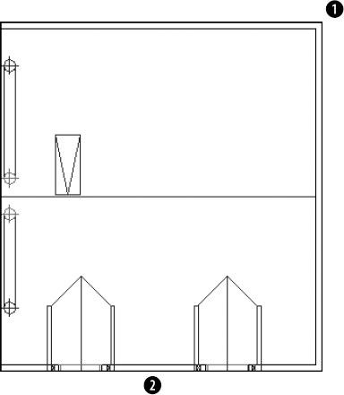
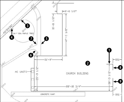
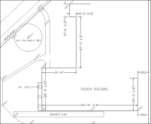
Four additional commands are commonly used in the process of constructing models. The BREAK command removes sections of objects at points that you specify. JOIN, a new command, joins co-linear lines, polylines, arcs, elliptical arcs, or splines. CHAMFER creates corners, and FILLET creates rounded corners.
Drawing a long line and then breaking it into two or more shorter lines is often much easier than drawing two separate lines. A common use for BREAK is to break a wall at a door or a window in an architectural floor plan. You specify two points on the object, and the command erases whatever is between those two points. Typically, you use object snaps to specify the points. Sometimes, you can use TRIM to break an object, but if you have no convenient cutting edge, you may find BREAK more efficient.
Select the object at one of the break points that you want to create. You then see the
Specify second break point or [First point]:prompt. Because you have already specified the first point, you can now specify the second point. The command breaks the object between the two points.Select the object by using any method of object selection. You then see the
Specify second break point or [First point]:prompt. Right-click and choose First point. At theSpecify first break point:prompt, pick the first break point. At theSpecify second break point:prompt, pick the second break point. The command breaks the object between the two points.
Tip
You can use BREAK to shorten an object. Pick one point on the object where you want the new endpoint to be. Pick the other point past its current endpoint to cut off the object at the point you picked on the object.
Note
Pend inserts a pipe break symbol in a line. Look for it in SoftwareChapter10Pend.
The opposite of breaking objects is joining them. The JOIN command lets you join lines, polylines, arcs, elliptical arcs, and splines. The objects must be along the same linear, circular, or elliptical path. The objects can overlap, have a gap between them, or touch end to end.
Select source object:Select the first object that you want to join. Select lines to join to source:Select the second object. (AutoCAD knows which type of object you've selected for the first prompt and inserts it into the second prompt.) You can continue to select other objects.Press Enter to end selection.
AutoCAD joins the objects.
A nice touch is the ability to close arcs (to circles) and elliptical arcs (to ellipses). If your first object is either type of arc, you see the Select arcs to join to source or [cLose]: prompt. Use the cLose option to close the arc.
Note
Note
The drawing used in the following exercise on breaking and joining objects, ab10-h.dwg, is in the Drawings folder on the DVD.
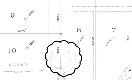
STEPS: Breaking and Joining Objects
Open
ab10-h.dwgfrom your DVD.Save the file as
ab10-09.dwgin yourAutoCAD Biblefolder. This is a site plan, as shown in Figure 10.27. Turn on Object Snap mode and set running object snaps for Endpoint and Intersection.
Repeat the BREAK command. At the
Select object:prompt, pick the circle (it's a maple tree) anywhere along its circumference. At theSpecify second break point or [First point]:prompt, right-click and choose First Point. At theSpecify first break point:prompt, pick the intersection atNote
AutoCAD and AutoCAD LT break circles counterclockwise. If you had picked

To break the line at
Select object:
Pick the line at. Specify second break point or [First point]:Right-click and choose First Point. Specify first break point:Move the cursor toto acquire it as a tracking point. Then move the cursor to the right onto the line you are breaking. When you see the Endpoint: Intersection tooltip, click. (You have no visual confirmation yet that you picked the right point.)Specify second break point: Move the cursor toto acquire it as a tracking point. Then move the cursor onto the line you are breaking. At the Endpoint: 4′-2 3/4″<0.0000 tooltip, click.
Start the JOIN command. At the
Select source object:prompt, select the line at
Save your drawing. It should look like Figure 10.28.
Note
The Express Tools contain a command, BREAKLINE, to create a break symbol. Choose Express Tools
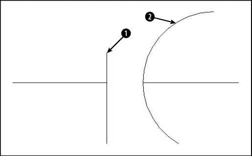
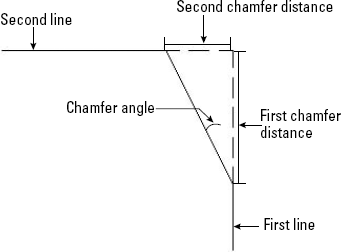
The CHAMFER command creates corners from two nonparallel lines. You can also chamfer xlines, rays, and polylines. You can simply extend the lines to meet at an intersection (a square corner), or create a beveled edge. If you create a beveled edge, you define the edge by either two distances or one distance and an angle relative to the first line that you're chamfering. Figure 10.29 shows the elements of a chamfered corner.
Chamfering is a two-step process. First you define how you want to chamfer the corner, specifying either two distances from the corner or a distance and an angle. Then you select the two lines that you want to chamfer.
To define two distances from the corner, right-click and choose Distance. At the
Specify first chamfer distance <0.0000>:prompt, type the first chamfer distance or press Enter to accept the default (which is the last distance that you defined). At theSpecify second chamfer distance <0.0000>:prompt, type the second distance. The default for this is always the first chamfer distance because equal chamfer distances are so common.To define a distance (from the corner) and an angle, right-click and choose Angle. At the
Specify chamfer length on the first line <1.0000>:prompt, enter a distance. This is the same as the first chamfer distance. At theSpecify chamfer angle from the first line <0.0000>:prompt, type the angle between the first line and the chamfer line.
Now that you have specified the settings that you want, you're ready to chamfer. Your distances or distance and angle are displayed as you just specified them. The command repeats the Select first line or [Undo/Polyline/Distance/Angle/Trim/mEthod/Multiple]: prompt. Select the first line. If you aren't creating a chamfer with equal distances, the order in which you select the lines is important. The command trims the first line selected by the first distance, and the second line selected based on either the second distance or the angle. At the Select second line or shift-select to apply corner: prompt, select the second line to chamfer the lines.
If the lines already intersect, the command trims them to create a corner. The pick points on intersecting lines should be on the part of the lines that you want to keep, not on the part of the lines that you want to trim off.
Tip
To quickly create a square corner if you have non-zero settings, press Shift as you select the second line. Of course, you can still set each distance to zero.
Note
Choose the Polyline option to chamfer an entire polyline at once. Chapter 16 covers polylines, and Chapter 24 discusses chamfering 3D models.
By default, CHAMFER trims the original lines that it chamfers. If you want to keep the full original lines when you add the chamfer line, choose the Trim option and choose No Trim. Use the Multiple option to continue the prompts and chamfer several corners in one command. The Undo option lets you undo your last chamfer and try again.
Note
The drawing used in the following exercise on chamfering lines, ab10-i.dwg, is in the Drawings folder on the DVD.
STEPS: Chamfering Lines
Open
ab10-i.dwgfrom your DVD.Save the file as
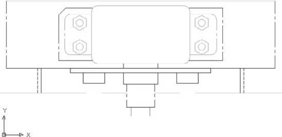
ab10-10.dwgin yourAutoCAD Biblefolder. This drawing is a very small section of a "porcupine" mixer, as shown in Figure 10.30.
Repeat the CHAMFER command. Follow the prompts:
Select first line or [Undo/Polyline/Distance/Angle/Trim/mEthod/Multiple]:
Right-click and choose Angle. Specify chamfer length on the first line <1>:9/16Specify chamfer angle from the first line <0>:45At the
Select first line or [Undo/Polyline/Distance/Angle/Trim/mEthod/Multiple]:prompt, pickSave your drawing.

The FILLET command creates rounded corners, replacing part of two lines with an arc. Fillets are often used in mechanical drawings. In certain cases, you can use FILLET instead of the ARC command to create arcs. As with CHAMFER, you can fillet lines, xlines, rays, and polylines — they can even be parallel. You can also fillet circles, arcs, elliptical arcs, and ellipses.
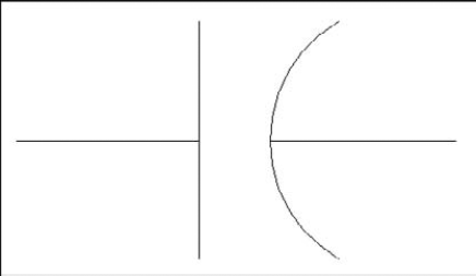
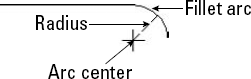
The FILLET command defines the fillet arc by its radius, as shown in Figure 10.32.
Like chamfering, filleting is a two-step process. First you define the radius of the fillet arc. Then you select the two lines that you want to fillet. You cannot select objects before the FILLET command.
To fillet, follow these steps:

Right-click and choose Radius.
At the
Specify fillet radius <0.0000>:prompt, type the radius you want. The default is either 0.0000 or the last radius that you specified.The command repeats the
Select first object or [Undo/Polyline/Radius/Trim/Multiple]:prompt. Select the first object that you want to fillet.At the
Select second object or shift-select to apply corner:prompt, select the second object that you want to fillet. This action creates the fillet.
By default, FILLET trims the original lines that it fillets, but the FILLET command recalls the last setting you used. If you want to keep the full original lines when you create a fillet, right-click and choose the Trim option, and then choose No Trim.
Note
Choose the Polyline option to fillet an entire polyline at once. Chapter 16 covers polylines, and Chapter 24 discusses filleting 3D models.
Filleting with a zero radius gives the same results as chamfering with distances set to zero. (See the previous section on chamfering.) If your existing settings are non-zero, you can press Shift as you select the second object to create a square corner.
The order in which you select the two objects to be filleted is not important. However, where you pick the objects is quite important. If two objects intersect, the command keeps the objects on the same side of the intersection as your pick point and fillets them. Those parts of the objects on the far side of the intersection are erased.
When you fillet arcs and lines, if more than one fillet is possible, FILLET connects the endpoints closest to your pick points. Filleting circles and lines can produce unexpected results. Sometimes you need to experiment to find the proper pick points.
Note
The drawing used in the following exercise on filleting objects, ab10-i.dwg, is in the Drawings folder on the DVD.
STEPS: Filleting Objects
Open
ab10-i.dwgfrom your DVD.Save the file as
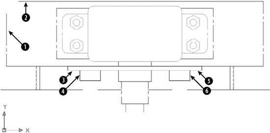
ab10-11.dwgin yourAutoCAD Biblefolder. This is the same drawing used in the previous exercise. It is shown in Figure 10.33.
At the
Select first object or [Undo/Polyline/Radius/Trim/Multiple]:prompt, pick the line atRepeat the FILLET command. At the
Select first object or [Undo/Polyline/Radius/Trim/ Multiple]:prompt, right-click and choose Radius. At theEnter fillet radius <5/8>:prompt, type 1/4At the
Select first object or [Undo/Polyline/Radius/Trim/Multiple]:prompt, right-click and choose Multiple. Pick the line atIf you want, you can connect the two loose lines that the fillets created and create some more fillets in the drawing.
Save your drawing. It should look like Figure 10.34.
You may need to mark areas of your drawings that contain revisions in order to draw attention to these revisions. A common method is to draw a revision cloud around the revised objects. Figure 10.35 shows a drawing with a revision cloud, which is a series of arcs that indicate that an area of the drawing has been revised.
To create a revision cloud, follow these steps:

At the
Specify start point or [Arc length/Object/Style] <Object>:prompt, you can choose from three options:To change the length of the arc, right-click and choose Arc Length. Then specify a new arc length. For a variable, hand-drawn look, you can specify a minimum arc length and a maximum arc length that is up to three times the length of the minimum.
To change a closed object into a revision cloud, right-click and choose Object. Then pick a circle, ellipse, closed polyline, or closed spline. You can choose to reverse the direction of the revision cloud. The object is converted to a revision cloud, and the command ends.
To choose from two available cloud styles, right-click and choose Style. At the next prompt, choose either the Normal or Calligraphy option. A calligraphy revision cloud has a variable line width so that it looks as if you drew it with a calligraphy pen.
Click where you want the revision cloud to start. You also see an instruction,
Guide crosshairs along cloud path ..., which means that you don't have to pick to create the arcs. You just have to move the crosshairs along the path of the desired cloud.Move the crosshairs counterclockwise to create a circular or elliptical shape. When you approach the start point, the command ends automatically. (You can end the cloud at any time by pressing Enter.)
Note
If you want, you can pick each arc endpoint to control the size of the arcs. However, if you move the crosshairs farther than the arc length, an arc is created automatically. REVCLOUD multiplies the arc length by the Overall Scale factor (see Chapter 15) to adjust for different scale factors.
A wipeout covers existing objects in order to clear space for some annotation or to indicate that the covered objects will be changed and should therefore be ignored. A wipeout is a polygonal area with a background that matches the background of the drawing area. The WIPEOUT command creates a polygon of the same color as the background of your drawing area.
To create a wipeout, follow these steps:

At the
Specify first point or [Frames/Polyline] <Polyline>:prompt, specify the first point of a shape that will cover existing objects. To use a polyline as the shape, right-click and choose Polyline. (The polyline can't contain any arcs when you use it for this purpose.) Then select the polyline and choose whether or not to erase the polyline.At the
Specify next point or [Undo]:prompt, if you specified a point, specify the next point.At the
Specify next point or [Close/Undo]:prompt, specify another point or use the Close option to close the wipeout shape. You can also press Enter to end the command and use the shape that you specified.
By default, the wipeout has a frame around it, using the current layer's color. You can hide the frames of all wipeouts by starting the WIPEOUT command, choosing the Frames option, and then choosing Off.
Note
You can create a background mask especially for text. This mask covers a rectangle around your text so that you can read the text more easily. For more information, see Chapter 13.
You can control objects by specifying parameters that constrain their relationships with other objects or their measurements. For example, you can constrain one line to be always perpendicular to another line, or you can constrain the diameter of a circle to a specific value. Using parameters adds intelligence to your drawing and helps to ensure accuracy of the entire drawing when you modify objects. Parameters can also save a huge amount of time that you would otherwise need to spend editing objects, because when you change one object, other objects automatically adjust to comply with their constraints.
Note
Parametric constraints are new for AutoCAD 2010. They are not available in AutoCAD LT. The feature includes two types of constraints: geometric and dimensional.
Figure 10.36 shows a model with several concentric geometric constraints and a diameter dimensional constraint.
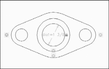
Figure 10.36. You can control object properties and relationships by applying geometric and dimensional constraints.
Geometric constraints apply to the geometric properties of objects. The basic principle is that the first object that you specify is the base object, and the second object that you specify moves or adjusts in accordance with the constraint. For example, if you have two lines at different angles and use the parallel constraint, the second line will rotate to become parallel with the base object. In most cases, you can specify a specific point on an object to manage the constraint.
To specify a geometric constraint for one or more objects, display the Parametric tab and use the Geometric panel. Each button is an option of the GEOMCONSTRAINT command. Table 10.2 lists the available geometric parameters and their functions.
Table 10.2. Geometric Parameters
Function | |
|---|---|
Coincident | Constrains a point on one object to be at a point on another object. The objects can be a line, polyline, circle, arc, ellipse, or spline. The first object can be a point object. Valid points are endpoints, midpoints, and centers (for arcs). |
Colinear | Constrains a second line or polyline to lie along the same line as a first line or polyline. Valid points are endpoints and midpoints. |
Concentric | Constrains a second arc, circle, or ellipse to have the same center as a first one. |
Fix | Locks an object in place. You can lock lines (by endpoint or midpoint), polylines (by endpoint or midpoint, and by center of arc segments), arcs (by center, endpoint, or midpoint), circles (by center), ellipses (by center and by endpoint or midpoint for elliptical arcs), and splines (by endpoint). |
Parallel | Constrains a second line or polyline to be parallel to the first. Valid points are endpoints and midpoints. |
Perpendicular | Constrains a second line or polyline to be perpendicular to the first. Valid points are endpoints and midpoints. |
Horizontal | Constrains a line or polyline segment to be parallel to the X axis. You can also use the 2 Points option to make two points horizontal. |
Vertical | Constrains a line or polyline segment to be parallel to the Y axis. You can also use the 2 Points option to make two points vertical. |
Tangent | Constrains curves to be tangent to other curves or lines. You can specify a line (endpoints or midpoints), polyline (endpoints, midpoints, or center of arc segments), and endpoints, midpoints, or centers of an arc, circle, or ellipse. |
Smooth | Creates a continuous curvature between two splines (or a spline and a line, arc, or polyline) that share a coincident endpoint. You need to create a coincident constraint between the endpoints of the two objects first. |
Symmetric | Constrains a point on a second object to be the same angle and distance from a symmetry line as a point on the first object. You can choose the endpoints and midpoints of lines, polylines, and arcs. You can choose centers of arcs, circles, ellipses, and polyline arc segments. |
Equal | Resizes lines and polyline segments to have equal length, as well as resizing arcs and circles to have equal radius. You can specify endpoints and midpoints of lines, polylines, and arcs, as well as the center of arcs, circles, and polyline arc segments. |
Note
Not every combination of parameters is possible. For example, a line can't have both horizontal and vertical parameters. When you try to apply a parameter that is impossible due to previous constraints, you get a message saying that applying the constraint would overconstrain the geometry.
By default, you see small, semitransparent icons for each geometric parameter. You can turn the display of these icons on and off, or turn them on for specific objects. Choose Parametric tab
If you pass your cursor over an icon, you see the name of the constraint. Also, the objects that it affects appear dashed.
The Auto Constrain feature only adds eight of the possible parameters, omitting Fix, Smooth, Equal, and Symmetric. You can specify which parametric constraints to apply and in which order. To do so, click the dialog box launcher arrow on the Geometric panel's title bar to open the Constraint Settings dialog box, and then click the AutoConstrain tab. The settings are self-explanatory.
For more precision, you can apply dimensional constraints, which apply a constraint based on a number or an equation. For example, you can specify a 4-unit distance between two lines. You can specify the dimensional constraint from scratch, or convert an existing dimension.After you create a dimensional constraint, you can change the constraint's value to modify the affected objects. Dimensional constraints show a lock next to their icon to distinguish them from geometrical constraints.
Note
Dimensional constraints have many similarities to dimensions. (I cover dimensions in Chapters 14 and 15.) You may want to turn your constrained objects into blocks so that you can use them again. Also, constrained objects can act like dynamic blocks. Certain features of constraints (parametric constraints) apply only to dynamic blocks. For more information on blocks and dynamic blocks, see Chapter 18.
To apply a dimensional constraint, choose the Parametric tab
Linear. Constrains the distance between two points. The points can be at any angle from each other, but measure only the vertical or horizontal distance. You can use the same types of points as for geometrical constraints. Use the Object option to apply a linear constraint to lines, polyline segments, or arcs.
Vertical. Constrains the distance between two points that are parallel to the Y axis. Otherwise, this constraint works just like the linear one.
Horizontal. Constrains the distance between two points that are parallel to the Y axis. Otherwise, this constraint works just like the linear one.
Aligned. Constrains the distance between two points that are not at orthogonal angles from each other.
Angular. Constrains the angle between lines, polyline segments, and arc endpoints (using the arc center as the angle vertex). You can use the 3 Points option to specify individual points.
Diameter. Constrains the diameter of a circle or arc.
The Form option of the DIMCONSTRAINT command lets you choose one of two forms (or formats) to apply to subsequent dimensional constraints that you create:
Dynamic. Dynamic constraints, the default, don't change size as you zoom in or out and have a predefined style, which includes a gray color. You can show or hide dynamic constraints by choosing Parametric tab
Annotational. Annotational constraints look like regular dimensions, and you can format how they appear. They use the current layer properties. (I cover layers in Chapter 11.) They plot, and so you can use annotational constraints both to constrain objects and in the place of dimensions.
Tip
You can display dynamic constraints only for selected objects. On the Parametric tab, in the Dimensional panel, click the dialog box launcher arrow on the panel's title bar. The Constraint Settings dialog box opens with the Dimensional tab on top. Uncheck the Show All Dynamic Constraints check box and check the Show Hidden Dynamic Constraints for Selected Objects check box. In the same place, you can control whether the dynamic constraint displays its name, value, or name and expression. When you're done, click OK.
To change the form of an existing dimensional constraint, select the constraint, display the Properties palette (Ctrl+1), and use the Constraint Form drop-down list.
AutoCAD doesn't let you over-constrain geometry. That means that you can't add more constraints than necessary. If you try to add another constraint, AutoCAD opens a message telling you that applying the constraint would over-constrain the geometry. In this situation, you can back out and add a different constraint, or you can create a reference dimension. A reference dimension is just for show; it doesn't actually constrain objects. You might use a reference dimension to show relationships that other constraints create, or to add a second label in a different location. You can change the reference property of a constraint in the Properties palette. AutoCAD displays reference constraints in parentheses.
AutoCAD gives each dimensional constraint a name and you can create expressions that reference another dimensional constraint. In this way, you can create relationships between objects. For example, the radius of a circle can be one half the distance between two lines. The result is that modifying one object then updates related objects; in the example, changing the distance between the lines would change the radius of the circle. The result is a powerful way to control the geometry of your drawing.
You edit and manage dimensional constraints in the Parameters Manager palette, as shown in Figure 10.37. The Parameters Manager lists existing dimensional parameters. You can modify these parameters and create user parameters. The Name column lists the name of each parameter. AutoCAD assigns a default name when you create a dimensional parameter, but you can change the name. Click a name to highlight it, enter a new name, and press Enter. Names cannot start with a number, contain spaces, or be more than 256 characters.
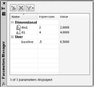
Figure 10.37. The Parameters Manager palette lets you modify dimensional parameters and create user parameters.
To change a value, you use the Expression column, not the Value column. For example, if you have a dimensional parameter that specifies a distance of 3.0 units and you want to change that value to 4.0 units, click the number in the Expression column so that it's selected, enter a new value, and press Enter. The objects adjust to be in accord with the new constraint.
You can enter expressions in the Expression column. For example, if you want the diameter of a circle to be two times the length of a line, and the parameter for the line is named length, you can enter length*2 for the circle's parameter. Then when you change the line parameter's value, which changes the length of the line, the circle's diameter automatically adjusts accordingly. In this way, you maintain the required relationships among objects.
You can also create user parameters. A user parameter can be a value or expression that you want to use as a basis for another parameter. It can be a number or equation.
Tip
To add trigonometric and other functions to an expression, click the expression, right-click, and choose Expressions. Then choose the function you want.
Note
The drawing used in the following exercise on using parametric constraints to constrain objects, ab10-j.dwg, is in the Drawings folder on the DVD.
STEPS: Using Parametric Constraints to Constrain Objects
Open
ab10-j.dwgfrom your DVD.Save the file as
ab10-12.dwgin yourAutoCAD Biblefolder. This drawing is shown in Figure 10.38. Set a running object snap for Endpoints. You want to be able to scale the plate, without changing the size of the circle, which represents a hole for a fixed-width axle. You also want to constrain the relationships between the objects.
To constrain the three lines to be of equal length, you only need to constrain two of the three lines. (If you try all three, you over-constrain the geometry.) Click the Equal button in the Geometric panel. At the
Select first object or [Multiple]:prompt, select the vertical line atYou want to be able to scale this plate, but you want to make sure that the circle's diameter doesn't change. In the Dimensional panel, click the Diameter button. At the
Select arc or circle:prompt, select the circle. At theSpecify dimension line location:prompt, pick a location. Then press Enter to end the command.Click the Home tab. In the Modify panel, choose Scale. At the
Select objects:prompt, click above and to the left of the plate and then click below and to the right, to create a selection window. Press Enter to end selection. At theSpecify base point:prompt, pick the lower-left corner of the plate. At theSpecify scale factor.... :prompt, enter 2Click the Parametric tab again. In the Manage panel, click Parameters Manager. Click the dia1 item and type hole
To prepare for the stretching action in the next step, you need some room above and below the model in the drawing area. If you don't have enough room, click the Pan button on the status bar and drag downward a little. Press Esc to end Pan mode.
Click the Home tab. In the Modify panel, click Stretch. At the
Select objects:prompt, pick atSave your drawing.
You can double-click objects to edit them. What happens after you double-click depends on the type of object. In most cases, double-clicking an object just opens the Quick Properties palette where you can change the object's properties. For more information about using the Quick Properties palette and Properties palette, see the section, "Editing with the Quick Properties Palette and the Properties Palette," later in this chapter.
When you double-click certain types of objects in a drawing, you see a dialog box that is specific to these objects, or a related editing command starts:
Attribute definition. Opens the Edit Attribute Definition dialog box (the DDEDIT command). See Chapter 18 for more information.
Attribute within a block. Opens the Enhanced Attribute Editor dialog box (the EATTEDIT command). See Chapter 18 for more information.
Block. Opens the Edit Block Definition dialog box. You can choose the block from a list and click OK to enter the Block Editor. See Chapter 18 for more information.
Hatch. Opens the Hatch Edit dialog box (the HATCHEDIT command). See Chapter 16 for more information.
Image. Opens the IMAGEADJUST command. See Chapter 27 for more information.
Livesection. Starts the LIVESECTION command. See Chapter 24 for more information.
Mline. Opens the Multilines Edit Tools dialog box (the MLEDIT command). Mlines are not available in AutoCAD LT, which has a similar feature, called Dlines. See Chapter 16 for more information.
Mtext or leader text. Opens the In-Place Text Editor (the MTEDIT command). See Chapter 13 for more information.
Spline. Starts the SPLINEDIT command.
Polyline. Starts the PEDIT command.
Text (TEXT or DTEXT commands). Opens the In-Place Text Editor (the DDEDIT command). See Chapter 13 for more information.
Xref. Opens the Reference Edit dialog box (the REFEDIT command). See Chapter 19 for more information.
Note
You can customize what happens when you double-click an object. For example, you could choose to display the Properties palette rather than the Reference Edit dialog box when you double-click an xref. See Chapter 33 for details.
The DBLCLKEDIT system variable specifies whether double-clicking opens a dialog box in these instances. To turn off double-clicking to edit objects, choose Application Button
Grips offer a way to edit objects without choosing commands. By using grips, you can quickly stretch, move, rotate, scale, copy, and mirror objects.
When you select an object without first choosing a command, the object appears highlighted with grips — small boxes at preset object snap points. (If you don't see grips, they may be turned off. See the "Customizing grips" section later in this chapter to find out how to turn them back on.) You can continue to select more objects in this way.
You then click to activate a grip and use the grip to manipulate the object. When the grip is activated, it turns red (by default). An activated grip is also called a hot grip, as shown in Figure 10.39. In some cases, you activate more than one grip at a time. To activate more than one grip, hold down Shift and then click the grips. If you activate a grip in error, click it again to deactivate it. Grips are so called because you can "hold on to" the object by dragging the grips with the mouse.
After you activate a grip, right-click with the mouse to open the Grip shortcut menu, which lists all the grip options. You can also press the Spacebar or Enter to cycle through five possible commands on the command line.
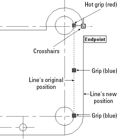
Figure 10.39. Moving a line. Grips appear at preset object snaps. You use the hot grip to manipulate an object.
As long as you're familiar with the STRETCH, MOVE, ROTATE, SCALE, and MIRROR commands, you can easily learn how to accomplish the same edits by using grips because the prompts are so similar. After you complete the edit, the object remains highlighted and the grips remain so that you can further edit the object. If you want to edit another object, press Esc once to remove the grips. Then select another object or objects or choose another command.
Note
If you use Dynamic Input, you can customize how many and which tooltips appear when you grip edit. Right-click the Dynamic Input button on the status bar and choose Settings to open the Drafting Settings dialog box with the Dynamic Input tab on top (I explain this dialog box in Chapter 4). Click the Settings button in the Dimension Input section to open the Dimension Input Settings dialog box. The settings here apply to grip editing. By default, the Show Two Dimension Input Fields at a Time option is selected. Although this setting usually works well, you can go down to one input field or specify additional fields. When you select multiple grips to edit an object, no Dynamic Input field appears.
Stretching with grips involves understanding how the grip points relate to the object. For example, you cannot stretch a line from its midpoint — if you think about it, there's no way to define in which direction to stretch the line. Also, you cannot stretch a circle, you can only scale it. Aside from these types of limitations, anything goes.
You can stretch one line. The result is similar to using the CHANGE command to change a line's endpoint. To stretch a line, select it, and click the grip at the endpoint that you want to stretch. You see the Specify stretch point or [Base point/Copy/Undo/eXit]: prompt on the command line.
STRETCH is the first grip-editing command on the command line. Simply specify the new endpoint for the line, using any method of specifying a coordinate, to stretch the line. The other options work as follows:
Base point lets you define a base point — other than the activated grip — and a second point. Right-click to open the Grip shortcut menu and choose Base Point. The option displays the
Specify base point:prompt. Define a base point. Again you see the originalSpecify stretch point or [Base point/Copy/Undo/eXit]:prompt. Define the second stretch point to stretch the line.Copy puts you in Multiple mode. Right-click to open the Grip shortcut menu and choose Copy. Again you see the original
Specify stretch point or [Base point/Copy/Undo/eXit]:prompt. Specify a new point to keep the original line, and create a new line stretched to the new point. You can continue to create new stretched lines.Undo undoes the last edit. Right-click to open the Grip shortcut menu and choose Undo.
eXit returns you to the Command prompt. Right-click to open the Grip shortcut menu and choose Exit. Esc also returns you to the Command prompt.
Stretching more than one line at a time is similar to the most common use of the STRETCH command. However, it can also be somewhat confusing.
As explained earlier in this chapter, when you use the STRETCH command, objects that cross the crossing window are stretched, while objects entirely within the crossing window are moved. When you stretch multiple lines, you should activate endpoint grips to stretch lines, and activate midpoint grips to move lines. Picking all those grips accurately can be difficult and time-consuming. Also, small objects that are close together create a lot of overlapping grips that are hard to select. For this reason, stretching multiple lines works best with simple models.
To stretch multiple lines, follow these steps:
Choose the objects that you want to stretch. The objects are highlighted and display grips. You can use any method of choosing objects — you are not limited to crossing windows.
Hold down Shift and pick each grip that you want to stretch. If there are internal objects that you want to move with the stretch, select their grips, too; these include the midpoints of the lines and arcs, and the centers of the circles.
Release Shift and pick a grip to use as a base point. You see the
Specify stretch point or [Base point/Copy/Undo/eXit]:prompt.Specify a new stretch point. You can also use any of the other options.
At the end of this section on grips, you have the opportunity to try them out in an exercise.
It's easy to move objects with grips. First, choose all the objects that you want to move. Then click any grip to activate it. This becomes the base point. Right-click to open the Grip shortcut menu and choose Move or press the Spacebar once. At the Specify move point or [Base point/Copy/Undo/eXit]: prompt, use any method to specify the second point. The selected objects move. The other options work as follows:
Base point lets you define a base point other than the activated grip. Right-click to open the Grip shortcut menu and choose Base Point. You see the
Specify base point:prompt. Define a base point. The originalSpecify move point or [Base point/Copy/Undo/eXit]:prompt returns. Define the second move point to move the objects.Copy puts you in Multiple mode and lets you copy objects. Right-click to open the Grip shortcut menu and choose Copy (or type c
Undo undoes the last edit. Right-click to open the Grip shortcut menu and choose Undo.
eXit returns you to the Command prompt. You can also press Esc.
Rotating with grips is very similar to using the ROTATE command. First, choose all the objects that you want to rotate. Then click any grip to activate it. This becomes the base point. Right-click to open the Grip shortcut menu and choose Rotate. At the Specify rotation angle or [Base point/Copy/Undo/Reference/eXit]: prompt, type in a rotation angle or pick a point to rotate the objects. The other options work as follows:
Base point lets you define a base point other than the activated grip. Right-click to open the Grip shortcut menu and choose Base Point. You see the
Specify base point:prompt. Define a base point. The originalSpecify rotation angle or [Base point/Copy/Undo/Reference/eXit]:prompt returns. Specify the rotation angle to rotate the objects.Copy puts you in Multiple mode and lets you copy objects. Right-click to open the Grip shortcut menu and choose Copy. Again, you see the original
Specify rotation angle or [Base point/Copy/Undo/Reference/eXit]:prompt. Specify a rotation angle to keep the original object and create a new rotated object where you specified. You can continue to create new objects.Undo undoes the last edit. Right-click to open the Grip shortcut menu and choose Undo.
Reference lets you specify both a reference angle and a new angle. Right-click to open the Grip shortcut menu and choose Reference. You see the
Specify a Reference angle <0>:prompt. Type an angle or pick two points to specify an angle. TheSpecify new angle or [Base point/Copy/Undo/Reference/eXit]:prompt appears. Type an angle or pick a point. This works like the Reference option for the ROTATE command. (See Chapter 9.)eXit returns you to the Command prompt. Right-click to open the Grip shortcut menu and choose Exit. Esc also returns you to the Command prompt.
Scaling with grips is very similar to using the SCALE command. First, choose all the objects that you want to scale. Then click any grip to activate it. This becomes the base point. Right-click to open the Grip shortcut menu and choose Scale. At the Specify scale factor or [Base point/Copy/Undo/Reference/eXit]: prompt, type a scale factor to scale the objects. The other options work as follows:
Base point lets you define a base point other than the activated grip. Right-click to open the Grip shortcut menu and choose Base Point. You see the
Specify base point:prompt. Define a base point. The originalSpecify scale factor or [Base point/Copy/Undo/Reference/eXit]:prompt appears. Define the scale factor to scale the objects.Copy puts you in Multiple mode and lets you copy objects. Right-click to open the Grip shortcut menu and choose Copy. You see the original
Specify scale factor or [Base point/Copy/Undo/Reference/eXit]:prompt. Specify a scale factor to keep the original object and create a new scaled object. You can continue to create new scaled objects.Undo undoes the last edit. Right-click to open the Grip shortcut menu and choose Undo.
Reference lets you specify a reference length and a new scale. Right-click to open the Grip shortcut menu and choose Reference. You see the
Specify reference length <1>:prompt. Type a length or pick two points to specify a length. You see theSpecify new length or [Base point/Copy/Undo/Reference/eXit]:prompt. Type a length or pick a point. This works like the Reference option for the SCALE command. (See Chapter 9.)eXit returns you to the Command prompt. You can also press Esc.
Mirroring with grips is similar to using the MIRROR command. First, choose all the objects that you want to mirror. Then click any grip to activate it. This becomes the first point of the mirror line. Right-click to open the Grip shortcut menu. Choose Mirror. At the Specify second point or [Base point/Copy/Undo/eXit]: prompt, specify the second point of the mirror line to mirror the objects.
Warning
By default, AutoCAD and AutoCAD LT erase the original objects. To keep the original objects, you must use the Copy option. This feature is the opposite of the MIRROR command, where the default is to keep the original objects.
The other options work as follows:
Base point lets you define a base point other than the activated grip, as well as a second point. Right-click to open the Grip shortcut menu and choose Base Point. You see the
Specify base point:prompt. Define a base point — that is, the first point of the mirror line. The originalSpecify second point or [Base point/Copy/Undo/eXit]:prompt appears. Define the second point of the mirror line to mirror the objects.Copy puts you in Multiple mode and lets you keep the original objects. Right-click to open the Grip shortcut menu and choose Copy. You see the original
Specify second point or [Base point/Copy /Undo/eXit]:prompt. Specify the second point to keep the original objects and create new mirrored objects. You can continue to create new mirrored objects.Undo undoes the last edit. Right-click to open the Grip shortcut menu and choose Undo.
eXit returns you to the Command prompt. You can also press Esc.
Note
The drawing used in the following exercise on editing with grips, ab10-k.dwg, is in the Drawings folder on the DVD.
STEPS: Editing with Grips
Open
ab10-k.dwgfrom the DVD.Save the file as
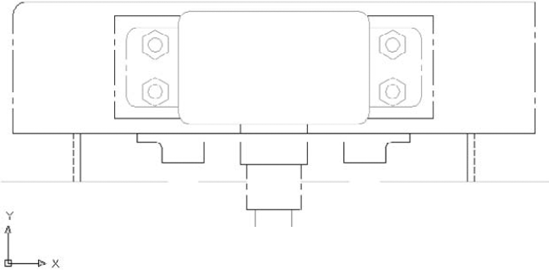
ab10-13.dwgin yourAutoCAD Biblefolder. This is a small section of a drive block, seen from above, as shown in Figure 10.40. Make sure that Ortho mode and Object Snap mode are on.Use a selection window to select the entire model. Now hold down Shift and place a selection window around the small circles and rectangle at the center of the model to deselect them.
Pick the grip at
Right-click and choose Mirror from the shortcut menu. You see the
Specify second point or [Base point/Copy/Undo/eXit]:prompt.Right-click and choose Copy so that the original objects that you mirror are not deleted.
At the
Specify second point or [Base point/Copy/Undo/eXit]:prompt, move the cursor to the right. You can see the mirror image of the model. Pick any point to the right (in the 0-degree direction) of the activated grip.Right-click and choose Exit to return to the command line. The original objects are still highlighted.
Use a large selection window to select all the new objects, including the small rectangle and circles in the middle. Everything (old and new) should be highlighted and display grips.
Pick the grip at
Pick the bottom-right grip to activate it. Right-click and choose Scale from the shortcut menu. At the
Specify scale factor or [Base point/Copy/Undo/Reference/eXit]:prompt, type .5Pick the grip at the midpoint of the bottom line. Right-click and choose Move from the shortcut menu. At the
Specify move point or [Base point/Copy/Undo/eXit]:prompt, type 0,−3Press Esc to remove all grips. Define a crossing window by picking first at
Hold down Shift and pick all the grips along the bottom three lines. Release Shift and pick the grip at the middle of the bottom line. At the
Specify stretch point or [Base point/Copy/Undo/eXit]:prompt, type 0,1If the stretch does not come out right (it might be hard to see and activate all the grips), choose Undo from the Standard toolbar to undo the stretch and try again.
Save your drawing.
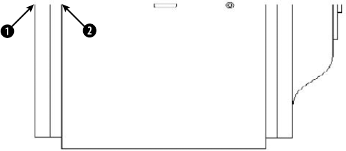
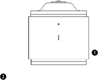
You can turn grips on and off and customize their size and color. Choose Application Button
By default, grips are enabled. Also by default, grips are turned off for blocks. (Chapter 18 covers blocks.) When grips are off for blocks, you see only one grip when you select a block; this is its insertion point. When grips for blocks are on, you see all the grips you would normally see for objects.
In the Grips section, you can choose the colors that you want for unselected and selected (hot) grips. Click the drop-down lists to choose a color.
The Grip Size section lets you drag the slider bar to set the size of the grips. Click OK after you have made the desired changes.
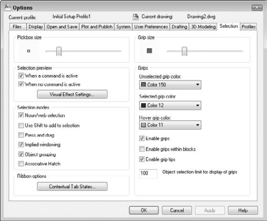
The Quick Properties palette and Properties palette are windows that show the properties of a selected object and allow you to change those properties by entering or choosing new values. The Quick Properties palette is small and is useful for simple, quick changes; it is also highly customizable. The Properties palette offers more options for each object.
By default, when you select an object, the Quick Properties palette appears, displaying some basic properties of the object, such as its layer, color, and linetype. Other properties that appear depend on the type of object. For example, you see the length of a line, as shown in Figure 10.43. To change an object's properties, enter or choose a new value in the Quick Properties palette. If you select more than one object, you see properties that apply to all the selected objects.
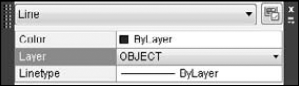
Figure 10.43. The Quick Properties palette shows you an object's properties in a small space and allows you to change those properties.
Right-click any blank area on the palette for further configuration:
Close. Closes the palette.
Customize. Opens the Customize User Interface dialog box, where you can define which objects open the palette and which properties appear. For more information, see Chapter 33.
Settings. Opens the Quick Properties tab of the Drafting Settings dialog box, shown in Figure 10.44, where you can control the functioning of the panel in one location. You can also set the default height of the palette to display more or fewer properties.
Location Mode. Choose Cursor or Float. By default, the palette displays at the cursor. Choose Float to display the palette in the drawing area, wherever you drag it. These options control the QPLOCATION system variable.
Auto-Collapse. By default, the palette is small and you usually need to expand it to see all the properties. You can uncheck this option to display the palette big enough to show all the properties.
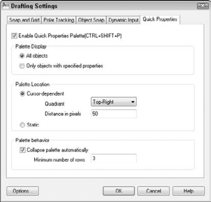
Tip
Click the Quick Properties button on the status bar to turn the Quick Properties palette on and off.
The rollover tooltip is a smaller version of the Quick Properties palette that appears when you hover your cursor over an object, without selecting it. You can't change properties in the rollover tooltip; they're just for your information. You can customize which properties appear, and synchronize the tooltip, with the Quick Properties palette; see Chapter 33 for more information.
The Properties palette displays an extended list of the properties of selected objects. You can also use the Properties palette to change the properties of objects.
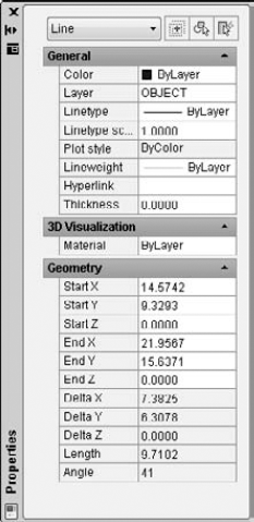
The auto-hide feature of the Properties palette makes it easy to work with the palette open all the time. Whenever the cursor moves off the palette, it collapses to just display the title bar. To auto-hide the palette, right-click the title bar and choose Auto-hide. You can also dock it; choose Anchor Left or Anchor Right from the title bar's shortcut menu. The Allow Docking item should also be checked; if it isn't, choose it from the same shortcut menu.
Tip
The Properties palette has its own undo function. Right-click the palette (but not on the item that you changed) in the Properties palette and choose Undo. Multiple levels of undo are available. For more information about palettes, see Chapter 26.
You can use the Properties palette to directly edit objects and to edit other object properties as well:
You can change the layer, color, linetype, linetype scale, and lineweight of objects (see Chapter 11).
You can edit text and text properties (see Chapter 13).
You can edit plot styles (see Chapter 17).
You can edit blocks (see Chapter 18).
You can edit hyperlinks (see Chapter 28).
To change values in the Properties palette, do one of the following:
Click a value, select the text, type a new value, and press Enter.
Click a value, click the down arrow to the right of the value, and choose from the drop-down list.

The information that you see in the Properties palette depends on the object selected. If you select more than one object, the palette shows properties that are common to those objects.
The Properties palette has three buttons in its upper-right corner: the Toggle Value of PICKADD Sysvar button, the Select Objects button, and the Quick Select button.
The Toggle Value of PICKADD Sysvar button turns PICKADD on and off. PICKADD changes how you select more than one object. When it's on (set to 1), which is the default, you can continue to select objects and they're added to the selection set. When it's off (set to 0), you need to press Shift to add objects to the selection set; otherwise, selecting an object deselects previously selected objects. Here's how to change the PICKADD variable:
Click the Select Objects button.
On the command line, type the selection method that you want (such as f for fence) as you would if a command were active or you had started the SELECT command.
Select the objects that you want.
Press Enter to end object selection.
Use the Properties palette to make the desired changes. (You can also start an editing command to use with the selected objects.)
Sometimes you need a more powerful way to select objects. For example, you may want to:
Select all the lines in your drawing to change their color.
Check the arc radii of all your fillets.
Find short line segments that should be erased.
As its name suggests, Quick Select is a quick, flexible, and simple way to create object selection filters. Use the FILTER command, which is covered in the following sections, to create more-complex filters or when you want to save filtering criteria for future use.
Start Quick Select in one of these ways:

With no command active, right-click in the drawing area and choose Quick Select.
Click the Quick Select button in the Properties palette.
Type qselect
The Quick Select dialog box opens, as shown in Figure 10.46.
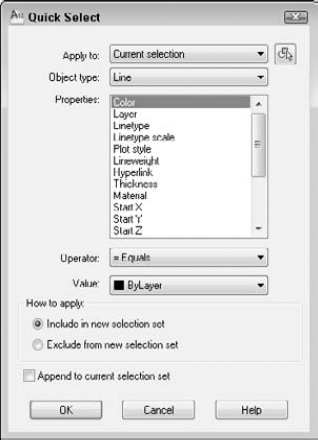
Figure 10.46. Use the Quick Select dialog box to quickly create a selection set of objects based on specified criteria.
To create a filter, start at the top of the dialog box and work your way down. Here's how it works:
Apply to. By default, the filter applies to the entire drawing, but you can use the Select Objects button to return to your drawing and select objects. The rest of the filter will then apply only to selected objects, which is called Current Selection in the drop-down list. If you use this feature at all, you would usually use a window to select an area of your drawing. (The Select Objects button is unavailable if Append to Current Selection Set is checked at the bottom of the dialog box.)
Object type. By default, the filter lists Multiple as the object type. Click the drop-down list to choose from the object types available in your drawing (or in your selection set if you created one), such as line, circle, ellipse, polyline, and so on. You can choose only one type of object. To create a filter that includes more than one type of object (but not all types), use the FILTER command, which I describe in the next section.
Properties. Here you choose the properties that you want to filter. (Most of these properties are covered in the next chapter.) The drop-down list includes all properties in the drawing's database; these properties depend on the object type you chose. You can choose only one property. The values in the next two sections depend on your choice in the Properties section. If you want to create a filter that specifies criteria for more than one property, use the FILTER command.
Operator. After you've chosen a property, you can set it equal to or not equal to a certain value. You can set certain properties as greater than or less than a value. You can use wild card matching characters (such as
*and?) for editable text. Choose the desired operator from the drop-down list. You can also select all objects that fit the previous criteria.Value. Here you finally choose the value for your property. For example, you can set the color equal (or not equal) to green or the linetype equal to DASHED. Choose the desired value from the drop-down list or enter a value in the text box.
Tip
You can choose Block Reference as the object type, Name as the property, and the name of a block as the Value to select all instances of that block. I cover blocks in Chapter 18.
How to apply. As soon as you create a filter, you can use it to create a selection set. To do this, check Include In New Selection Set. To use Quick Select to select everything except objects that meet your selection criteria, choose Exclude from New Selection Set.
Append to current selection set. Check this box to add objects that meet your criteria to an existing selection set.
Click OK to select the objects that meet your criteria, and close the dialog box. You can start a command and use the selection set. If the command must be started before selecting objects, you can use the Previous option (type p
Note
The Express Tools include two commands to create filtered selection sets. Type fastselect
The advantage of using the FILTER command over Quick Select is that you can create more-complex filters and save them.
To create a filter, type filter
Note
The selection filter finds only colors and linetypes of objects that have been specifically set as such, rather than as part of a layer definition. Chapter 11 covers layers, colors, and linetypes.
Use the Select Filter section of the dialog box to specify a filter. The drop-down list lists all the possible filters. Click the arrow to display the drop-down list. You can choose from several types of items:
Objects
Object properties such as color or layer
Object snaps such as arc center or circle radius
Logical operators such as
AND, OR, andNOT(these logical operators combine filter specifications in various ways)
The first step is to choose a filter. For example, to create a filter that chooses all lines, choose Line from the drop-down list. If the item chosen does not need any further clarification, click Add to List. The filter appears in the box at the top of the dialog box. This filter would appear as Object = Line.
Many filters require a value. You have two ways to enter a value:
If you choose an object that can be listed, the Select button becomes active. Click it and choose the value that you want. For example, if you choose Color or Layer, you can choose from a list of colors or layers.
If you choose an object that can have any value, the boxes below the drop-down list become active. They are labeled X, Y, and Z, but this is misleading. These boxes are used for X, Y, and Z coordinates only when you choose a filter requiring coordinates, such as Viewport Center. In most cases, you use the X text box to give the filter a value. In this situation, the Y and Z boxes are not used. For example, if you choose Text Height, you type the height in the X box.
Keep in mind that you don't always want to specify that a filter equals a value. For example, if you want to create a filter that selects all circles with a radius less than 0.75, then when you choose Circle Radius, the X box becomes active. Click the arrow to display the drop-down list of relational operators and then choose one. Table 10.3 lists the relational operators.
To add a second filter, you first decide on the relationship between the first and the second filters and then assign a logical operator. Logical operators always come in pairs — when you begin one operator, you must also end it. The logical operators are at the end of the drop-down list of filter objects.
Note
When two or more filters are listed without logical operators, the filter calculates them as if they were grouped with the AND operator. This means that the filter selects only objects that meet all the criteria specified.
Table 10.4 explains the four logical operators, which are called grouping operators because they group filter specifications together. The Example column explains the results of two filter specifications: Color = 1-Red and Object = Circle.
Table 10.4. Logical (Or Grouping) Operators Used for Selection Filters
Operator | Explanation | Example |
|---|---|---|
| Finds objects that meet all criteria. | Finds red circles. |
| Finds objects that meet any of the criteria. | Finds all red objects and all circles. |
| Finds objects that meet one criterion or the other but not both. Requires two criteria between | Finds red objects that are not circles and circles that are not red. |
| Excludes objects that meet the criteria. May have only one criterion between | If the |
Click Substitute and choose a saved filter to insert a saved filter into the filter you're currently defining. To add filters based on existing objects, choose Add Selected Object. This action adds all the properties of the object to the filter definition, which is often more than you want.
Figure 10.47 shows a filter that selects all lines and all polylines. The XOR operator finds objects that meet one criterion or the other but not both. Obviously, no object can be both a line and a polyline. This is a good example of a filter that you cannot create by using Quick Select.
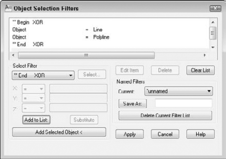
After you've completed the filter, you should save it. Even if you don't think you'll use it again, you may make an editing error in the drawing while using it and have to go back to it. To save a filter, type a name in the Save As text box and click Save As.
You edit a listed filter by using three buttons:
Edit Item. Choose the line containing the item and click this button to edit the item. The object name now appears in the drop-down list, and you can specify new values for it.
Delete. Choose Delete to delete a chosen item in a filter.
Clear List. Choose Clear List to clear all the items in a filter and start over.
To choose a named filter to edit, choose it from the Current drop-down list.
You can use filters in two ways. Most often, you choose a command first and then realize that you need a filter to select the objects. In this situation, follow these prompts:
Select objects:'filterDefine the filter in the Object Selection Filters dialog box. Click Apply. Applying filter to selection. Select objects:Typeallor use a large selection window to select all the objects that you want to consider in the filter. x found Select objects:
Exiting filtered selection. x found
Select objects:
The command's usual prompts then continue.
Alternatively, you can start the FILTER command and define the filter. Click Apply. At the Select objects: prompt, type all or use a selection window. Press Enter to end object selection. Then start the editing command and use the Previous selection option to select the filtered objects.
Note
The drawing used in the following exercise on using selection filters, ab10-l.dwg, is in the Drawings folder on the DVD.
STEPS: Using Selection Filters
Open
ab10-l.dwgfrom the DVD.Save the file as
ab10-14.dwgin yourAutoCAD Biblefolder. Notice that two lines of text appearing in the middle of the drawing, plus the text at the bottom of the drawing, are black/white rather than blue like all the other text. You want to check the color of all the text and correct it if necessary.Right-click the drawing area and choose Quick Select. In the Quick Select dialog box, click the Object Type drop-down list and scroll down until you see Text. Choose it.
In the Properties section, Color should be selected. If not, select it. In the Operator section, choose <> Not Equal. In the Value section, choose ByLayer. Include In New Selection Set should be chosen. Append to Current Selection Set should not be checked. Click OK to select three items of black/white text.
Press Esc to deselect the objects and remove the grips. Now you'll try the same thing, using the FILTER command, but adding a level of complexity.
Type filter
In the Select Filter drop-down list, choose Text. Click Add to List. At the top, the filter reads
Object = Text.From the Select Filter drop-down list, choose
**Begin AND(this is toward the bottom of the list) and click Add to List.From the Select Filter drop-down list, choose Color. In the drop-down list next to X:, choose
! =(not equal). Then choose Select. In the Select Color dialog box, choose BYLAYER. Click OK. In the Object Selection Filters dialog box, choose Add to List. The BYLAYER color number displays as 256. (Layers and colors are covered in the next chapter.)You may want to select only the smaller text, and not the heading at the bottom of the drawing, where you know that the larger text's height is greater than .1 and the smaller text's height is smaller than .1. From the Select Filter drop-down list, choose Text Height. From the X: drop-down list, choose
<(less than). In the text box to the right of X:, type .1. Choose Add to List.From the Select Filter drop-down list, choose
**End ANDand click Add to List.In the Save As text box, type bad text. Click Save As. The Object Selection Filters dialog box should look like the following:
Object = Text
**Begin AND
Color !=256 - ByLayer
Text Height < 0.100000
**End AND
Click Apply.
At the
Select objects:prompt, type allIn the Properties panel of the Home tab choose ByLayer from the Color Control drop-down list. The two text objects change to the BYLAYER layer, where they change to a blue color like all the other text.
Save your drawing.
Groups let you save a selection set of objects so that you can easily select them whenever you need to edit them. If you have a certain set of objects that you need to edit as a group, and a busy drawing that makes their selection time-consuming, then groups are for you. After you set up the group, you can pick any object in the group to automatically select all the objects in the group. An object can belong to more than one group.
Note
Although both AutoCAD and AutoCAD LT include the group feature, the dialog box for creating and managing groups is different for AutoCAD and AutoCAD LT. Over the next few sections, be sure to note which program I'm discussing.
To create or modify a group, type group
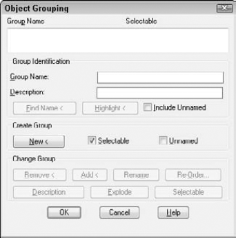
To create a new group in AutoCAD, follow these steps:
Type a name in the Group Name text box. You can use a maximum of 31 characters with no spaces. You can use the hyphen (-) and underscore (_) anywhere in the name.
If you want, you can type a description of up to 448 characters. The description can include spaces.
Click New. AutoCAD returns you to your drawing with the
Select objects:prompt. Select the objects that you want to be in the group. Press Enter to end object selection. AutoCAD returns you to the dialog box.Click OK.
The Group Identification section of the Object Grouping dialog box also has a Find Name button. Use this feature to find the name of the group to which an object belongs. AutoCAD lets you select an object and then lists the group's name or names.
The Highlight button highlights a group. First choose a group from the list in the Object Grouping dialog box. Click Highlight and AutoCAD returns to your drawing and highlights all the objects in your group. Click Continue to return to the dialog box. Use this feature when you aren't sure which group you want to work with.
To change a group in AutoCAD, click any existing group in the Group Name list at the top of the dialog box. The buttons in the Change Group section all become active. You can then do the following:
Remove. AutoCAD switches to the drawing area with the
Select objects to remove from group ...:prompt. Select objects to remove and press Enter to end object removal. AutoCAD returns you to the dialog box. Click OK.Add. AutoCAD switches to the drawing area with the
Select objects to add to group ...:prompt. Select objects to add and press Enter to end object selection. AutoCAD returns you to the dialog box. Click OK.Rename. Choose the group that you want to rename. Change the name in the Group Name text box. Click Rename. The name changes in the Group Name list at the top of the dialog box. Click OK.
Re-Order. Each object in the group has a number, starting with zero. In rare cases, if you are running a program that processes the members of a group, the order may be important. Choose a group. Click Re-Order. In the Order Group dialog box, to reverse the order of all the objects, click Reverse Order. Otherwise, click Highlight. AutoCAD opens a small Object Grouping message box with Next and Previous buttons. At the bottom-right corner, the box displays
Object: 0, and one of the objects in the group is highlighted. Click Next to move from object to object. You'll probably need to write down the number of each object. Click OK to return to the Order Group dialog box. Complete the following text boxes:Remove from position. This text box is the position number of the object that you want to move.
Replace at position. This text box is the new position number that you want for the object.
Number of objects. This text box is the object number or range of numbers that you want to reorder.
Description. Updates a description for the group. Type a new description in the Group Identification section of the dialog box. Then click Description.
Explode. Removes the group entirely. All the objects remain in your drawing, but they are no longer grouped.
Selectable. Toggles the selectability of the group. If a group is selectable, then selecting one object of the group selects the entire group. If a group is not selectable, then selecting one object of the group does not select the entire group. This option lets you temporarily work with one object in the group without having to explode the group. You can also press Ctrl+Shift+A to toggle the selectability of the group.
To create or modify a group in AutoCAD LT, type group
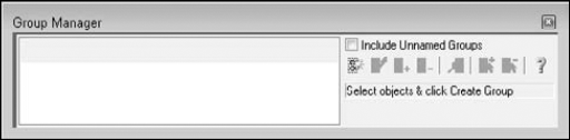
To create a new group in AutoCAD LT, follow these steps.
With the Group Manager open, select the objects that you want to include in the group. (An object can belong to more than one group.)

Type a name for your group and press Enter. You can use a maximum of 31 characters with no spaces. You can use the hyphen (-) and underscore (_) anywhere in the name.
If you want, click in the Description column and add a description for your group.
A light bulb appears in the Selectable column to indicate that the group is selectable (that is, functioning as a group). To close the Group Manager, click its Close button at the upper-right corner of the window. You can now use your group.
Use the Group Manager toolbar to manage your groups. To work with your groups, click any existing group. You can then do the following:
Ungroup. Deletes the group. All the group's objects become individual objects again.
Add to Group. Select an object or objects not in the group and click this button to add the selected object or objects to the group.
Remove from Group. To remove an object from a group, click the Selectable icon. You can now choose individual objects in the group without selecting the entire group. Click in your drawing and pick the object that you want to remove. Then click the Remove from Group button.
Details. Opens a window with more information about the group and its objects.
Select Group. To select the group from the Group Manager, select the group name and click the Select Group button.
Deselect Group. Deselects the group.
To toggle a group from selectable to not selectable, click the group's icon in the Selectable column. When a group is not selectable, you can individually select its objects.
Using a group is very simple. If a group is selectable, just pick any object in the group to select all the objects in the group. You can then edit the objects in the group as a whole. If you need to temporarily edit one object in a group, then turn off the group's selectability, as described in the previous sections.
You can change the selectable status of all groups in your drawing by choosing Application Button
This chapter covered all the more advanced editing commands. You read about:
Mirroring objects
Creating rectangular and polar arrays
Creating an offset of an object
Aligning objects
Trimming and extending objects
Stretching objects
Lengthening (and shortening) objects
Breaking and joining objects
Creating chamfered corners and fillets for square, beveled, and rounded corners
Drawing revision clouds and using wipeouts
Constraining objects with geometric and dimensional parameters
Using grips to stretch, move, mirror, rotate, and scale objects
Double-clicking objects to edit them
Using the Quick Properties panel and the Properties palette to see the properties of objects and edit them
Creating filtered sets of selected objects with the Quick Select feature and the FILTER command
Creating and using named groups of objects
In the next chapter, I cover layers, colors, linetypes, and lineweights.