
Installing AutoCAD and AutoCAD LT, once something to avoid as long as possible, is now a breeze. For all practical purposes, all that you need to do is to put the DVD or CD-ROM into your DVD or CD-ROM drive and follow the instructions. Nevertheless, I provide some helpful tips and comments in this appendix. As with all software that comes with an installation program, you should close all other applications before starting, including antivirus software.
In this appendix, I also cover many ways to configure AutoCAD and AutoCAD LT so that these programs function best for your circumstances.
The installation process involves some preparation, the actual installation, and finally authorization.
Before you install, make sure that your system meets the minimum, and preferably the recommended, requirements:
Operating system. Windows XP (Home or Professional) with Service Pack 2; Windows Vista (Enterprise, Business, Ultimate, or Home Premium) with Service Pack 1.
AutoCAD and AutoCAD LT are also offered as 64-bit versions that are available for Windows XP Professional x64 Edition with Service Pack 2 and Windows Vista 64-bit with Service Pack 1.
Processor speed (32-bit). Pentium 4 or AMD Athlon Dual Core, 1.6 GHz or higher for Windows XP or 3.0 GHz for Windows Vista, but I would recommend 2.0 GHz as a minimum for 2D. For 3D work, 3.0 GHz or higher is recommended.
Processor speed (64-bit). AMD Athlon 64 or Opteron with SSE2 technology, Intel Pentium 4, or Xeon with Intel EM64T support and SSE2 technology.
RAM (memory). 2GB for 2D work and 2GB or more for 3D work; however, 512MB is acceptable for AutoCAD LT running on Windows XP, or 1GB if you are running Windows Vista.
Video. 1024 × 768 VGA or higher with true color. For 3D work in AutoCAD, you should use a screen resolution of 1280 × 1024 with 32-bit color, and at least 128MB of RAM on a Direct3D capable, workstation-class graphics card. Autodesk certifies specific graphics cards for use with AutoCAD's 3D features. To see which cards are certified, use the 3DCONFIG command (AutoCAD only). In the Adaptive Degradation and Performance Tuning dialog box, click the Check for Update button to go to a Web page on Autodesk's Web site that lists graphics cards and their test results.
Using the 3DCONFIG command, you can specify either Direct3D or software acceleration.
Note
If your graphics card is not certified, your computer won't explode, but it could crash when using some effects, display artifacts (extra visual effects), or fail to display some features, such as materials and lights.
Hard drive. 1 to 1.5GB free for installation depending on whether you are installing AutoCAD or AutoCAD LT on a Windows 32- or 64-bit operating system; for permanent storage, about 1GB for 2D features on a 32-bit release of Windows or 1.5GB on a 64-bit release of Windows; 2GB for 3D features, and 550MB for AutoCAD LT.
Pointing device. Mouse, trackball, digitizer puck, or other device.
CD-ROM/DVD drive. Any speed (for installation only).
Browser. Internet Explorer 7.0 or later minimum; in most cases, you can use other browsers as well.
Optional equipment. A printer or plotter; a digitizing tablet; a network interface card if you're using the network version of AutoCAD, or Internet-enabled features of AutoCAD.
In order to install AutoCAD or AutoCAD LT, you may need administrator permission to write to the folder where you're installing AutoCAD, the system registry, and the Windows System folder.
Note
AutoCAD 2010 and AutoCAD LT 2010 can coexist with earlier releases of both programs. When you install, the Migrate Custom Settings feature detects if you have an earlier release on your computer and guides you through the process of migrating custom features. Nevertheless, if you have customized files that you want to keep, it's always good to back them up before installation. To read the ReadMe file before starting to install, insert the AutoCAD 2010 DVD or the AutoCAD LT 2010 CD-ROM into the DVD/CD-ROM drive and click Read the Documentation. On the HTML page that is opened, click the Readme (.chm) link. You can also read the ReadMe file at the end of installation.
You're now ready to install AutoCAD 2010 or AutoCAD LT 2010. Here are the steps:
Place the DVD or CD-ROM in your DVD/CD-ROM drive. In most cases, the setup procedure starts automatically. If it does not, choose Start

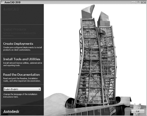
When the Welcome screen appears, click the type of installation that you want:
Install Products. One seat (location) standard installation.
Create Deployments. Set configurations to distribute to client workstations.
Install Tools and Utilities. Administrative, reporting, and network licensing tools (AutoCAD only). The CAD Manager Tools are also here (and included in AutoCAD LT as well). See the section later in this chapter on the tools and utilities.
The Install screen provides links to all the installation tasks and information that you need, as shown in Figure A.1. In these steps, I clicked Install Products (for a stand-alone installation).
Note
Some plotter manufacturers, such as Hewlett-Packard, offer a special driver that optimizes the plotter for use with AutoCAD. Check the manufacturer's Web site for the latest driver.
On the next screen, select the products you want to install. The choices are AutoCAD 2010 or AutoCAD LT 2010 and Autodesk Design Review 2010. If you are using AutoCAD and your product offers more than one language option, choose the language option you want to use. Click Next.
Read the software license agreement. Click the Print button if you want to print the agreement. Click "I Accept" and then click Next.
On the Product and User Information screen, enter the serial number and product key along with your name and organization. In AutoCAD only, this information is permanent and you can't change it without uninstalling AutoCAD. In AutoCAD LT, you can change this information on the System tab of the Options dialog box (OPTIONS command). Click Next.
On the Review - Configure - Install screen, you review the installation settings. To use these default values, click Install and wait while the software installs. To change them, select the product you want to change from the Select the Product to Configure drop-down list and click the Configure button.
If you choose to configure, on the Select the License Type screen, select a license type: stand-alone or network license. Click Next. On the Select the Installation Type screen, select the installation type: You can choose typical or custom. You can also choose to install the Express Tools (highly recommended) and the material library (used for 3D rendering) if you are installing AutoCAD. In addition, you can choose to create a desktop shortcut and specify the install location for AutoCAD or AutoCAD LT. If you choose a custom installation, you can choose which of the following items you want by checking or unchecking their check box. Then click Next.
CAD Standards. For more information, see Chapter 26 (AutoCAD only).
Database. External database connectivity. For more information, see Chapter 20 (AutoCAD only).
Dictionaries. For more information, see Chapter 13.
Drawing encryption. Password protection. For more information, see Chapter 26 (AutoCAD only).
Express Tools. Supplemental commands (AutoCAD only).
Fonts. For more information, see Chapter 13.
Autodesk Impression Toolbar. Allows you to export a view to Autodesk Impression, another Autodesk product that creates a hand-drawn look (AutoCAD only).
Autodesk Seek. Allows you to access and use content from Autodesk Seek in your drawings. Autodesk Seek is an online resource for building product information, including 3D models, 2D drawings, visual images, and product specification data.
Material Library. You use materials for rendering (AutoCAD only). This item is not checked by default.
New Features Workshop. For more information, see Chapter 3.
License Transfer Utility. Tools to transfer a stand-alone license among computers.
Migrate Custom Settings. A utility to help you to keep your custom settings when you upgrade.
Initial Setup. A utility which allows you to do some very basic customization of the program before you start it the first time.
Reference Manager. Manages external files connected to a drawing. For more information, see Chapter 27 (AutoCAD only).
Samples. Sample drawings that you can use for your reference.
Tutorials. Mostly programming tutorials (AutoCAD only).
You can go back later and add items if you decide that you need an item that you didn't initially install. When you're done, click Next. On the Include Service Pack screen, specify any service packs from
Autodesk.comor a local/network drive that you might want to install with the product. Click Next. On the Configuration Complete screen, click Configuration Complete. You return to the Review - Configure - Install pane. Click Install. This takes a few minutes. You can take a break or watch the status bar that appears during the process.You're now done, and you have an opportunity to read the README file — always a good idea — by checking the appropriate check box. Click Finish. The README file opens if you have asked for it. (If you want to read it later, in AutoCAD or AutoCAD LT, click the Help button located to the right of InfoCenter and click the Contents tab. Then choose User's Guide
Note
You may see a dialog box asking you to restart your computer. Because you shouldn't have any other applications open, you can do so immediately.
Don't forget to reenable your antivirus software.
You're done! You can now choose Start
Attach Digital Signatures. A security feature for attaching a digital signature to a drawing (see Chapter 26).
AutoCAD 2010 or AutoCAD LT 2010. Starts AutoCAD or AutoCAD LT.
Batch Standards Checker. Checks CAD standards for a group of drawings (see Chapter 26) (AutoCAD only).
License Transfer Utility. Helps you move a license from one computer to another.
Reference Manager. Manages and reports on xrefs, images, and other files associated with a drawing (see Chapter 26; AutoCAD only).
Migrate Custom Settings. Contains the Migrate From a Previous Release item that launches the Migrate Custom Settings dialog box to help you keep your custom settings from a previous release as you upgrade. This stand-alone application usually runs automatically when you start the program the first time. From the sub-menu, you can also select items that allow you to import and export custom settings between different computers running the same release. You can export settings and files for use on another computer. You can then import those settings to the destination computer.
AutoCAD 2010 does not come with the VBA feature; you need to download it. This is part of a long-term plan to transition to .NET and VSTA (Visual Studio Tools for Applications), Microsoft technologies that software companies can incorporate into their products for programming customization. Microsoft has stopped supporting VBA and has not made it available for 64-bit computers; hence the transition plan.
You can download a VBA enabler for free from Autodesk at www.autodesk.com/vba-download. Installing this enabler allows VBA code to function as before.
If you have multiple licenses, you may want to use the network license utilities. Network licenses allow you to more flexibly manage multiple sets of AutoCAD. At the first screen of the Installation Wizard, choose Install Tools and Utilities. Here you can install the Autodesk Network License Manager and Autodesk AutoCAD 2010 Network License Activation Utility. There's also a reporting utility, SAMreport-Lite, for tracking network license usage.
The Autodesk CAD Manager Tools feature allows CAD Managers to control certain general features of AutoCAD and AutoCAD LT, including which content is available in the Communication Center and if DesignCenter Online is accessible from the DesignCenter palette. This feature is therefore essential for stand-alone installations as well.
Check the items that you want to install and click Next. Then follow the instructions, which vary according to your choices. For information about networking licensing, click the Documentation link on the installation screen and open the Network Licensing Guide. There are also guides for stand-alone installations.
After you install AutoCAD or AutoCAD LT, you can add features by using the following procedure:
Choose Start
In the dialog box, choose AutoCAD 2010 or AutoCAD LT 2010 and then click Change, Change/Remove, or Uninstall/Change (depending on your version of Windows).
The software Setup Initialization feature starts. Click Add or Remove Features.
In the dialog box, check a feature, or uncheck an existing feature. Click Next.
Click Next again. The software is updated.
Click Finish.
You may be prompted to restart your computer.
As with earlier releases, for security purposes, Autodesk requires that you activate AutoCAD and AutoCAD LT. (Certain customers, such as subscription customers, are exempt from the activation process.) When you first open AutoCAD or AutoCAD LT, the Activation dialog box opens. Click Activate to authorize the program or Run the Product to start using the program without activating it. If you click Activate, you will first enter your serial number or Group ID. You receive this number with your product or subscription. Then enter your product key, which also comes with your product or subscription. Click Next.
To activate and register, leave the Get an Activation Code option selected and click Next. Click Next and follow the instructions for your choice. If you are registering online (the default option), the Registration - Activation Confirmation page should be displayed. Click Finish.
You can use the product for 30 days while waiting for the activation code. When you get it, choose the Enter an Activation Code option and either paste it from the Clipboard or type it in.
AutoCAD or AutoCAD LT is now ready to use. By default, your system is configured to use the current system pointing device and the current system printing device. You can further configure AutoCAD and AutoCAD LT by using the Options dialog box and Initial Setup. The Options dialog box and Initial Setup are covered later in this appendix.
Note
The Express Tools menu, toolbars, ribbon tab, and ribbon panels are automatically included when you choose to install Express Tools. Express Tools includes three toolbars and a ribbon tab with several panels. To display these toolbars, switch to AutoCAD Classic workspace from the Workspace Switching button on the status bar, and right-click in any toolbar area that doesn't contain a toolbar. Choose Express and then choose a toolbar from the sub-menu. The ribbon tab and its panels are part of the default workspace, so you see them automatically. This applies to AutoCAD only.
If your Express Tools don't appear, you may need to activate them. Enter expresstools
When you first open AutoCAD or AutoCAD LT, if you have an earlier release of AutoCAD or AutoCAD LT on your system, the Migrate Custom Settings dialog box opens. This gives you a chance to keep many of your custom settings. Choose the options that you want to keep.
Also when you start AutoCAD or AutoCAD LT for the first time, the Initial Setup dialog box appears. From Initial Setup, you can do some basic customization of AutoCAD or AutoCAD LT. After you customize AutoCAD or AutoCAD LT with Initial Setup, the New Features Workshop opens. You can choose to view it right away, later (meaning that it opens each time you start the program), or not at all. You can always access it by clicking the drop-down arrow of the Help button to the right of InfoCenter and choosing New Features Workshop. The tutorials review the basics of new features.
A workspace is a configuration of toolbars, menus, ribbon tabs, and dockable windows (palettes and the command-line window). You can create workspaces so that you can quickly switch from one configuration to another. For example, when you are creating, organizing, and saving blocks, you might want the DesignCenter and Tool Palettes window displayed.
AutoCAD comes with three workspaces: AutoCAD Classic, 2D Drafting & Annotation, and 3D Modeling. AutoCAD LT comes with two workspaces, 2D Drafting & Annotation and AutoCAD LT Classic. For both programs, 2D Drafting & Annotation is the default workspace and it displays the ribbon. In many cases, you will want to change these workspaces to suit your drawing needs.
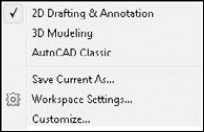
The easiest way to create a workspace is to start with the workspace closest to the one that you want to use, display toolbars, menus, ribbon tabs, and palettes the way you want them, and then choose Save Current As from the pop-up list of the Workspace Switching button on the status bar, as shown in Figure A.2. In the Save Workspace dialog box, name the workspace and then click Save. You can use this same method to modify an existing workspace. Make the changes and choose the current workspace in the Name drop-down list of the Save Workspace dialog box. Click Save, and then click Replace when asked whether you want to replace the workspace.
If you want to make sure that you don't forget anything, you can use the Customize User Interface dialog box. This method lets you pick and choose from the complete list of menus, toolbars, and dockable windows. Follow these steps:
Type cui

In the Customizations in All Files pane, double-click the Workspaces item to expand it.
To create a new workspace, right-click the Workspaces item and choose New Workspace. Then choose the new workspace to specify its settings. To edit an existing workspace, choose that workspace. The Workspace Contents pane appears to the right.
Tip
You can create a new workspace based on an existing workspace by right-clicking the workspace you want to duplicate under the Workspaces node, and choosing Duplicate.
In the Workspace Contents pane, click the Customize Workspace button. All the Quick Access toolbars, ribbon tabs, toolbars, and menus in the Customizations In pane now have check boxes next to them.
To add (display) or remove (hide) the Quick Access toolbar, ribbon tabs, toolbars, and menus, expand those items. Check or clear check boxes to specify the Quick Access toolbar, ribbon tabs, toolbars, and menus that you want to display or hide for that workspace. Don't forget to expand the Partial Customization Files item so that you can specify the Quick Access toolbar, ribbon tabs, toolbars, and menus for those files as well. As you add or remove items, they appear or disappear from the list in the Workspace Contents pane.
To specify the details of how each item should appear, click the item to show its properties in the Properties pane, where you can edit such properties as the location of a toolbar, its orientation (floating or docked), and its X and Y position. You can't edit menu properties.
To specify dockable window settings, which don't appear in the Customizations in All Files pane, double-click the Palettes item in the Workspace Contents pane. Choose any window to edit its properties in the Properties pane.
To save your changes, click the Customize Workspace button at the top of the Workspace Contents pane.
Click OK to close the Customize User Interface Editor.
To switch between workspaces, click the Workspace Switching button on the right side of the status bar, and choose one of the workspaces.
If you make changes to the interface display, such as displaying a toolbar, this change does not automatically become part of the workspace. However, AutoCAD remembers that last state of the interface, and if you close and re-open AutoCAD, that toolbar is displayed.
You can specify that you want to save changes that you make to the interface display to the workspace. Click the Workspace Switching button and choose Workspace Settings to open the Workspace Settings dialog box. Choose the Automatically Save Workspace Changes option and click OK. If you want to choose which changes are saved, keep the default Do Not Save Changes to Workspace option, and manually modify the current workspace, replacing the current one, as explained in the previous section. You can also use the Workspace Settings dialog box to organize the list of workspaces by changing their order in the list and adding separators to group certain workspaces together. Use the My Workspace drop-down list in the dialog box to assign a workspace to the My Workspace button on the Workspaces toolbar. You can control AutoCAD's settings (but not AutoCAD LT's) with profiles, which are different from workspaces. I discuss profiles later in this appendix.
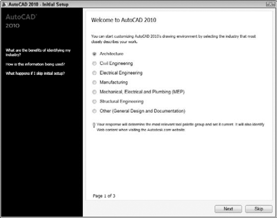
Initial Setup, shown in Figure A.3, allows you to perform basic customization of AutoCAD or AutoCAD LT. You can specify which industry best describes the type of drawings you work on, configure the user interface by choosing which task-based tools you want to use, and choose the default drawing template you want when creating a new drawing.
Note
Initial Setup is new for AutoCAD 2010 and AutoCAD LT 2010. This feature helps you to customize AutoCAD, based on your specific needs.
On the initial page, choose the industry that best describes your work. The industry you choose helps to identify Web content that is relevant to you on Autodesk's Web site, determine which tool palette group to display in the Tool Palette Window, and specify the default drawing template when creating a new drawing. Click Next.
On the Optimize Your Default Workspace page (AutoCAD only), check which task-based tools you would like to add to your default workspace. You can choose from 3D modeling, rendering, review and mark up, and sheet set tools. Click Next. On the Specify a Drawing Template File page, choose the default drawing template you want to use when creating a new drawing. AutoCAD assigns the template you select to the QNEW command. You can also set this by going to the Options dialog box, clicking the Files tab, expanding the QNEW node, and using the Default Template File Name item. Click Finish to end the Initial Start process and start the program.
When you complete Initial Setup and start the program, you have a new current workspace named Initial Setup Workspace. If you are using AutoCAD, you also have a new user profile named Initial Setup Profile to store the changes made with Initial Setup.
Initial Setup appears each time you start the program until you complete Initial Setup or uncheck the Remind Me the Next Time AutoCAD 2010 (or AutoCAD LT 2010) Starts check box. If you need to run Initial Setup again, choose Application Button
AutoCAD and AutoCAD LT have many options and settings that you can modify to suit your particular needs. Because you usually configure the software once when you first install, and only go back to these settings occasionally, it is easy to forget them. Knowing the available options is worthwhile; sometimes these options can make your life so much easier.
You can customize what appears in the status bar of the application window. For example, if you never use lineweights, you can remove the Show/Hide Lineweight button on the status bar.
To customize the status bar, click the down arrow at the right end of the status bar or right-click in an empty area on the status bar to display the status bar menu. Click any item to hide the item if it's checked or to display the item if it isn't checked. For each additional item, you need to click the down arrow or right-click again to re-open the menu.
You configure many features of the application by using the Options dialog box. Choose Apply to configure a setting and keep the dialog box open. Choose OK to configure a setting and close the dialog box.
Note
In the Options dialog box, items that are saved with the drawing display the blue and yellow drawing icon next to them. These settings change when you open other drawings that have different settings. Other settings are saved in the Windows Registry and do not change from drawing to drawing.
Take the time to browse through all the tabs in the Options dialog box so that you know what is available. You change many of these settings only rarely after the initial run-through. Choose Application Button
Tip
A quick way to access the Options dialog box is to right-click in the drawing or command-line area with no objects selected, and choose Options.
The Files tab lets you configure search paths, as well as specify filenames and locations. You'll probably most often use the Support File Search Path, which contains a listing of the folders that AutoCAD uses to search for menus, fonts, linetypes, and hatch patterns. Rather than add your customized menus, hatches, and so on to an existing support folder, you can create a folder especially for these files and add the folder to the Support File Search Path.
The default location for support files is the first listing under the Support File Search Path item. This location may vary, depending on your operating system. However, you can also use Program FilesAutoCAD 2010Support or Program FilesAutoCAD LT 2010Support, which is listed as one of the support locations.
As you click an item in the main listing of the dialog box, you see an explanation at the bottom. To edit the item, double-click the item or click the plus sign to the left of the item. You can then click a subitem and remove it, or click Add to add a subitem. Click Browse to find a folder or file rather than type it. Some other commonly used settings on the File tab are:
Project Files Search Path. The search path for xrefs (AutoCAD only).
Automatic Save File Location. Where the software automatically saves files if you don't.
Template Settings. Default locations for various templates. You can set the default template for the QNEW command here. When you do so, clicking the QNew button on the Quick Access toolbar automatically opens a new drawing with this template.
The Display tab, shown in Figure A.4, contains settings related to the display that you see on your screen.
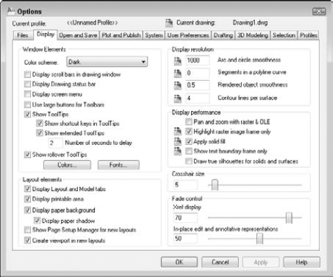
The Windows Elements section determines whether you see scroll bars, the screen menu, large toolbar buttons, tooltips, and rollover tooltips. (The screen menu is not available in AutoCAD LT.) You can also set the colors and fonts for the various screen elements. For example, by clicking Colors, you can change the background color of the Model and Layout tabs.
Note
AutoCAD 2010 contains separate background settings for 3D environments, with separate settings for parallel and perspective projections.
The Layout Elements section creates display settings for paper space layouts. Most are checked by default. You can set the following items:
The Display Layout and Model Tabs option determines if you see the tabs at the bottom of the drawing area. If you uncheck this box, you see the Model and Layout buttons on the status bar. You can switch between these settings without using the Options dialog box by right-clicking the tabs or buttons.
Uncheck the Display Printable Area option to hide the dashed line that you usually see around a layout. The dashed line represents the margin of the paper and, therefore, shows you the printable area.
Uncheck the Display Paper Background option to avoid seeing the edge of the paper and the gray background. This setting makes a layout tab look very much like the model tab. If this item is checked, you can uncheck the Display Paper Shadow item to get rid of the shadow effect that makes the paper look like it's slightly above the surface of the gray background.
Check the Show Page Setup Manager for New Layouts option to display the Page Setup Manager when you click a new layout tab. (See Chapter 17 for information on the Page Setup Manager.) This item is unchecked by default.
Uncheck the Create Viewport in New Layouts option to display layouts with no viewport. This setting is useful if you always want to set up your own viewport configurations.
The Display Resolution section sets arc and circle smoothness (also accessible by using the VIEWRES command), the number of segments in a polyline curve (the SPLINESEGS system variable), rendered object smoothness (the FACETRES system variable), and contour lines per surface (the ISOLINES system variable). The last two items are not available in AutoCAD LT, because they apply to 3D objects.
The Display Performance section offers settings that you can use to increase display speed. For example, several settings affect the way AutoCAD displays raster images. You can turn off FILLMODE, which applies solid fill in wide polylines, donuts, and hatched objects. AutoCAD LT has only the text boundary and solid fill items.
The Crosshair Size section sets the size of the crosshairs as a percentage of the entire screen. The default is 5. You can type a new number in the text box or drag the slider bar. To create crosshairs that cover the entire screen, use a setting of 100.
Note
You can now adjust the fade intensity of an attached xref in both AutoCAD and AutoCAD LT, and the fade intensity of an xref when editing it in place. I discuss xrefs in Chapter 19.
The Fade Control section controls the fading intensity of xrefs when you display or edit them. The Xref Display setting controls how much an attached drawing (xref) fades into the background of a drawing. The In-place Edit and Annotative Representations setting specifies the fading intensity for objects during in-place reference editing. This setting affects how much objects that you are not editing are faded, compared to objects that you are editing. The default is 50 percent. For more information, see Chapter 19. This last setting applies to both AutoCAD and AutoCAD LT, but in AutoCAD LT, you can only change it via the XFADECTL system variable.
The Open and Save tab, shown in Figure A.5, contains settings related to opening the program and files, as well as saving drawings.
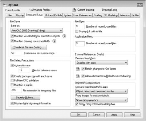
The File Save section specifies the default drawing type and whether or not a thumbnail preview image is saved. You can see this preview when you want to open a new drawing and set the view to Preview. You can separately specify thumbnails for sheet sets.
Note
Annotative scaling was introduced in AutoCAD 2008 and AutoCAD LT 2008 and is not supported in earlier releases. As a result, there is an option to specially preserve those scales when opening the file in older versions of AutoCAD and AutoCAD LT. When you check Maintain Visual Fidelity for Annotative Objects, each scale representation of your annotative objects is saved as a separate block on a separate layer. These layers are automatically frozen according to which annotation scale is current (visible). If you don't use this option, the older drawing will only have objects from the annotative scale on the Model tab. More objects could appear in model space (depending on the ANNOALLVISIBLE system variable) and paper space viewports in varying sizes. This option is checked by default to facilitate using annotative objects in earlier releases.
Note
You can control whether the drawings you create support large objects. If large-object compatibility is not enabled, then AutoCAD 2010 allows you to create large 3D objects and drawings that can't be saved to a previous release. If you need to work with users that use a release prior to AutoCAD 2010 or AutoCAD LT 2010, be sure to check the Maintain Drawing Size Compatibility check box (or set the LARGEOBJECTSUPPORT system variable to 0).
Setting the Incremental Save percentage enables you to control when AutoCAD or AutoCAD LT saves the entire drawing, as opposed to just your changes — an incremental save. The default is 50 percent, which avoids too many long, full saves.
In the File Safety Precautions section, set the default time between automatic saves. The other settings in this section are:
Create Backup Copy with Each Save. By default, AutoCAD and AutoCAD LT create backup drawings whenever you save a drawing. Backup drawings have the same name as your drawing, but with an extension of
.bak. Although you probably spend some time erasing these drawings, they can be very useful if a drawing becomes corrupted. You can change their extension to.dwgand open them as drawing files. However, you can also turn off this feature. Unfortunately, you can't control where the backup files are stored.Full-Time CRC Validation. Check this item if data that you import is becoming corrupted and you suspect a hardware problem. A cyclic redundancy check performs a validation during the importing process and can help you troubleshoot this problem (AutoCAD Only).
Maintain a Log File. Keeps a log file that records the contents of the text window. Each time you work in AutoCAD, the new material is added to the end of the existing log file, so you should periodically edit or delete material from the log file. Use the Files tab to control the log file location.
File Extension for Temporary Files. Sets the filename extension for temporary files that are created while you're working. By default, the extension for these files is
.ac$. Use the Files tab to control the temporary file location.
Use the Security Options button to set options for passwords and digital signatures. See Chapter 26 for more details. AutoCAD LT doesn't include the password feature.
In the File Open section, you can set how many of the most recently used drawings you want to see at the bottom of the File menu. The default is nine, which is also the maximum setting. You can also choose whether or not you want to see the full path on the File menu listing and on the application window title bar.
Note
In the Application Menu section, you can set how many of the most recently used drawings you want to see displayed in the Recent Documents list. The default is nine, and 50 is the maximum setting.
In the External References (Xrefs) section, you can turn on and off demand loading of external references. When the Retain Changes to Xref Layers setting is checked (which it is by default), any changes that you made to xref layer properties and states (such as freezing a layer) are saved. When you re-open the drawing containing the xref, these changes are retained. Finally, you can set whether the current drawing can be edited in-place when someone else is referencing it. The last setting applies to both AutoCAD and AutoCAD LT, but in AutoCAD LT you must use the XEDIT system variable. For more information, see Chapter 19.
Note
If you are an AutoCAD LT user, you can now specify if other users can edit your current drawing in-place if it is attached to another drawing.
In the ObjectARX Applications section (AutoCAD only), you have settings related to ObjectARX applications and proxy graphics created by ObjectARX applications. ObjectARX is a programming interface for creating applications that work with AutoCAD. By default, the application is loaded when you either use one of the application's commands or open a drawing containing a custom object created by the application. You can further restrict when the application is loaded to reduce demands on memory. In the Proxy Images for Custom Objects drop-down list, you can control how custom objects created by an ObjectARX application are displayed.
The Plot and Publish tab, shown in Figure A.6, contains settings related to plotting and publishing, including plot-style table settings. Later in this appendix, I explain how to configure a plotter.
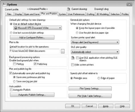
In the Default Plot Settings for New Drawings section, you set the default plotter/printer for new drawings and whether or not to use the same settings that you used the last time you plotted. As soon as you create plot settings for a drawing, those settings are saved with the drawing. Click Add or Configure Plotters for access to the Add-a-Plotter Wizard and existing plot configuration files. If you use a template, the plot settings in the template take precedence over the settings here.
The Plot to File section sets the default location for the file when you plot to a file. The Background Processing Options section determines whether plotting and publishing occur in the background (so that you can continue to work) or in the foreground. By default, background plotting is off for plotting and on for publishing (using the PUBLISH command). The Plot and Publish Log File section specifies whether to create a log file specifically for plotting and publishing operations.
In the Auto Publish section, you can set options for automatically creating DWF, DWFx, or PDF files every time you save or close a drawing. You do this to make sure that your DWF, DWFx, or PDF files are always up-to-date with your drawings. Click the Automatic Publish Settings button to open the Auto Publish Settings dialog box. I describe these settings in Chapter 28. Then check the Automatic Publish check box.
In the General Plot Options section, you can choose whether to keep the paper size specified on the layout tab or use the plotter's default paper size when you change plotters. You can also decide whether AutoCAD alerts you and creates an error log when the drawing is spooled through a system printer because of a port conflict.
In the same section, you can set a value for the quality of plotted OLE objects. You can choose from Monochrome, Low Graphics, High Graphics, and Automatically Select. The default is Automatically Select. Check the Use OLE Application When Plotting OLE Objects check box for the best quality when plotting OLE objects. Check the Hide System Printers check box to repress the display of Windows system printers on the list of printers in the Plot and Page Setup dialog boxes, so that you can't inadvertently print to your printer rather than to your plotter.
The Specify Plot Offset Relative To section determines how plot offsets (which you set in the Plot or Page Setup dialog box) work. Click the Plot Stamp Settings button to specify what you want to include if you add a plot stamp when plotting.
Click the Plot Style Table Settings button to decide whether to use color-dependent or named plot styles for new drawings, and choose a default plot-style table. You can also set default plot styles for layer 0 and objects. Click the Add or Edit Plot Style Tables button to go to the Plot Styles folder where the plot-style tables are stored. You can then double-click the Add-A-Plot Style Table Wizard to create a new table or open an existing table for editing. For more information on plotting and plot-style tables, see Chapter 17.
The System tab contains a number of settings that affect how your computer works with AutoCAD or AutoCAD LT, as well as some general settings. Figure A.7 shows the System tab.
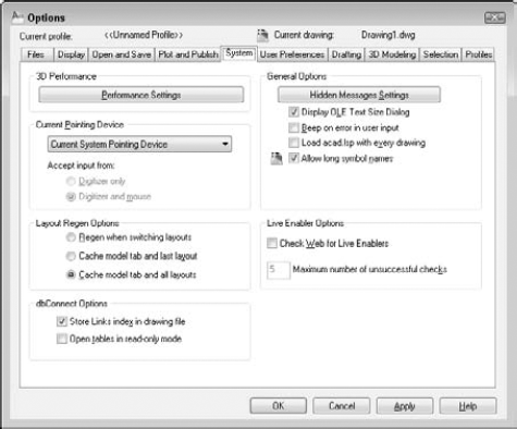
In the 3D Performance Settings section (AutoCAD only), click the Performance Settings button to open the Adaptive Degradation and Performance Tuning dialog box, as shown in Figure A.8.
Note
AutoCAD 2010 analyzes your computer system and degrades the display, based on the settings in this dialog box. For example, if your graphics card is not certified, materials and textures do not display by default. (You can easily turn them on. See Chapter 22 for more information.)
On the left side of the dialog box, you can turn Adaptive Degradation off by unchecking the check box at the top. Then you can set the level at which degradation starts to function. By default, this is five frames per second, which refers to the speed at which your monitor refreshes the display. In the Degradation Order box, you can do two things:
Uncheck items that you don't want to degrade. For example, you may always want to see materials and textures.
Change the order of degradation. Items at the top degrade first. Select an item and click the Move Up or Move Down button to change the order.
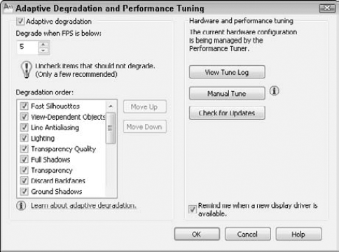
Figure A.8. The Adaptive Degradation and Performance Tuning dialog box allows you to specify how AutoCAD displays 3D features in relation to your computer system's capabilities.
You may need to see the results you get before making these decisions.
The right side of the dialog box contains information about performance tuning. Click View Tune Log to see the Performance Tuner Log window. Here you can see if your graphics card is certified, which just means that Autodesk has tested it and recommends it. The bottom of the window shows the effects on specific features, such as current acceleration driver, enhanced 3D performance, the Gooch shader, and full-shadow display.
Click the Manual Tune button to change the settings. For example, you can choose to enable hardware acceleration, even if your graphics card is not certified. Hardware acceleration means that your graphics card's capabilities are used. (When hardware acceleration is turned off, AutoCAD uses software acceleration to try to display the screen properly.) Autodesk says that you do this at your own risk, but you may find that this works for you. For example, you may have an excellent graphics card, but Autodesk may not have tested and certified it yet. You can also turn off specific features, such as full-shadow display, which involve intensive computer capabilities. If your card cannot support a specific feature, you can have AutoCAD reproduce the effect during plotting by checking the Emulate Unsupported Hardware Effects in Software When Plotting check box.
In the lower section of the dialog box, you can adjust features that don't require hardware acceleration, such as the display of backward-facing faces of solids, transparency, and tessellation lines (the apparent smoothness of curved objects created by using many short lines or triangles). The Tessellation cache is useful if you are displaying 3D objects in more than one viewport. You can also reset the setting to their recommended values. Click OK when you're done.
So, how do you know which graphics cards are certified? Click the Check for Updates button in the Adaptive Degradation and Performance Tuning dialog box to go to Autodesk's Web site and see a list of recommended cards. When you're done with the Adaptive Degradation and Performance Tuning dialog box, click OK to return to the Options dialog box.
In the Current Pointing Device section of the Options dialog box, you choose Wintab Compatible Digitizer ADI 4.2 if you have a digitizer. If you have a digitizing device, you can choose to accept input from only the digitizer, or both the digitizer and the mouse.
Note
If you're installing a digitizer, follow the instructions provided by the digitizer manufacturer to configure Windows for the Wintab driver. You need to configure the digitizer to work with Windows.
In the Layout Regen Options section (AutoCAD only), you can choose to cache (save in memory) the model and layout tabs to avoid regenerations when you switch among the tabs.
In the dbConnect Options section (AutoCAD only), you can choose whether to store the index of database links in the drawing file to enhance performance during Link Select functions. You can also choose to open database tables in read-only mode; however, you won't be able to edit them.
AutoCAD LT has a User Name section that contains your name and organization. This is derived from the information that you provided at installation. You can change this name. The REVDATE command, which is available only in AutoCAD LT, uses this name to place a time stamp on your drawing.
In the General Options section, you can do the following:
Bring back dialog boxes that have a Don't Display This Warning Again check box (that you checked). Click the Hidden Message Settings button to choose from dialog boxes that you checked.
Turn off the display of the OLE Text Size dialog box when inserting OLE objects into AutoCAD drawings.
Tell AutoCAD to beep (or to remain silent) when it detects an invalid entry.
Determine whether AutoLISP loads
acad.lspinto every drawing that you open. By default, this box is not checked, meaning that onlyacaddoc.lspis loaded into every drawing (AutoCAD only).Disable long names for layers, dimension styles, blocks, linetypes, text styles, layouts, UCS names, views, and viewport configurations for compatibility with prior releases and customization.
In the Live Enabler Options section, you can decide when you want to check for object enablers. Object enablers let the user display and use custom objects in drawings, even when the application that created them is unavailable. For example, if you send a customer who is using Release 2000 a drawing with associative dimensions, that customer can use an object enabler to view those dimensions.
The User Preferences tab, shown in Figure A.9, offers a variety of preference settings.
In the Windows Standard Behavior section, you can turn double-click editing on or off. Double-click editing determines what happens when you double-click an object. (You can customize this process in the Customize User Interface Editor, as I explain in Chapter 33.) You can also disable the shortcut menus that appear when you right-click in the drawing or command area. A right-click is then equivalent to pressing Enter.
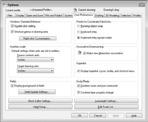
You can customize what happens when you right-click. Click Right-Click Customization to open the dialog box shown in Figure A.10.
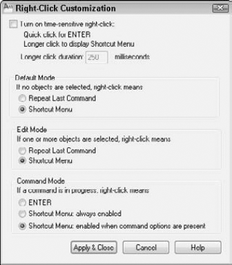
At the top of the Right-Click Customization dialog box, you can turn on the time-sensitive right-click feature.
With time-sensitive right-clicking, a quick right-click is equivalent to pressing Enter. For example, it repeats the last command, or ends the LINE command (and other commands that require Enter to end). A longer right-click (hold your finger on the mouse slightly longer) opens the shortcut menu. You can specify the length of time required for the longer right-click, which is 250 milliseconds by default.
In the Default Mode section, if you haven't turned on time-sensitive right-clicking, then you can choose the Repeat Last Command option if you don't want to use shortcut menus. In the Edit Mode section, you can choose the Repeat Last Command option to disable the shortcut menus only when one or more objects are selected, but no command is in progress. When you do this, right-clicking automatically repeats the most recent command. In the Command Mode section, you have three choices if you haven't turned on time-sensitive right-clicking:
Choose the ENTER option to disable the shortcut menus whenever a command is in progress. You then have to use the keyboard to choose command options.
Choose the Shortcut Menu: Always Enabled option to always have the shortcut menu available.
Choose the Shortcut Menu: Enabled When Command Options Are Present option as an in-between option. The shortcut menu is now available when the command has options, but when the command has no options, right-clicking is like pressing Enter.
Click Apply & Close to close the Right-Click Customization dialog box and return to the User Preferences tab of the Options dialog box.
In the Insertion Scale section of the User Preferences tab, you can specify default units for inserted objects (source contents units) and drawings (target drawing units) when dragging objects into a drawing from the DesignCenter or i-drop, or using commands like INSERT or XATTACH. When you don't use the INSUNITS system variable (saved in your drawing), this setting determines the units to apply. You can choose anything from inches to parsecs!
In the Fields section, you can turn on and off the gray border around fields. (The border doesn't plot; it just indicates to you that the text is a field.) Click the Field Update Settings button to specify when fields are automatically updated. By default, they update when you open, save, plot, eTransmit, or regenerate a drawing.
Click the Block Editor Settings button to open the Block Editor Settings dialog box, where you can control the display in the Block Editor.
Note
The Block Editor has been updated; the Block Editor Settings dialog box gives you more control over colors, font, and so on.
In the Authoring Objects section, you control the color of parameters and grips in the Block Editor along with orientation of labels for parameters. The Parameter Font section controls the text and font style for parameter labels, while the Parameter and Grip Size section controls parameter and grip size.
The Constraint Status section controls the colors assigned to geometric constraints based on the constraints' current status. The three settings in the lower-left corner of the Block Editor Settings dialog box control the display of constrained objects, parameters with value sets, and the action bar. Click Reset Values to restore the default values in the Block Editor Settings dialog box. Click OK to return to the Options dialog box.
Click the Initial Setup button to open Initial Setup and perform some basic customization of AutoCAD or AutoCAD LT. For more information on Initial Setup, see the "Using Initial Setup" section earlier in this chapter.
In the Priority for Coordinate Data Entry section, you specify which has priority: running object snaps or keyboard entry. By default, keyboard entry has priority except in scripts, so you can use running object snaps when picking points on the screen, but override them when you want to type in coordinates.
In the Associative Dimensioning section, choose whether you want new dimensions to be associative and thus automatically adjusting as their associated objects change size.
In the Hyperlink section, you can disable the hyperlink cursor (which appears when you pass the cursor over a hyperlink) and the hyperlink shortcut menu, as well as the hyperlink tooltip that appears when you pass the cursor over a hyperlink.
The Undo/Redo section has only one setting: You can choose to combine consecutive zooms and pans into one command when you use the U or UNDO command. You may do several zooms and pans together, but you probably don't want to step backward through each one individually. This feature is on by default.
Click the Lineweight Settings button to open the Lineweight Settings dialog box. For more information on lineweights, see Chapter 11.
In the Lineweight Settings dialog box, you can select a lineweight from the Lineweights list to set it current. There are three standard lineweight styles: ByLayer, ByBlock, and Default. The Default value is 0.01 inches or 0.25 mm. All new layers have a default setting of Default. You can also set any specific width that you want. In the Units for Listing section, choose Millimeters or Inches. The default is Millimeters, probably because pen widths for pen plotters are traditionally defined in millimeters. Checking the Display Lineweight check box is equivalent to clicking the LWT button on the status bar. In the Default drop-down list, you can change the default lineweight that new layers automatically use.
With the Adjust Display Scale slider, you can control how lineweights are displayed on the Model tab. (Lineweights on a paper space layout are displayed in real-world units.) On the Model tab, lineweights are displayed in pixels, using a proportion of pixel width to real-world unit value. Depending on the resolution of your monitor, you may want to adjust the display scale to better see different lineweights.
Tip
You can see the results of any display scale change immediately in the Lineweights list on the left of the dialog box. Scroll down to the bottom to see the difference for wider lineweights.
Click Apply & Close to return to the User Preferences tab of the Options dialog box.
Click the Edit Scale List button to open the Edit Scale List dialog box. Here you can customize the list of scales so that you always have the scales that you need (and don't have the scales that you never use). I discuss the scale list in Chapter 5.
The Drafting tab, shown in Figure A.11, includes AutoSnap and AutoTrack settings. In the AutoSnap Settings section, you can disable the marker (that visually indicates each object snap), the magnet (that draws the cursor to the object snap), and the tooltip (that says which object snap you've found). By default, the aperture is not displayed with AutoSnap markers because the combination can be confusing. You can also choose a color for the AutoSnap marker. Click the Colors button to change the color of the AutoSnap marker item. You can also change the marker size by dragging the control bar.
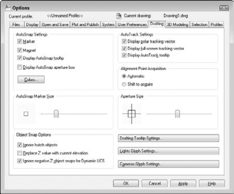
In the Object Snap Options section, you can turn off the option to ignore hatch objects. By default, you cannot snap to hatch objects. If you want to snap to hatch objects, uncheck the check box. You can also choose the Replace Z Value with Current Elevation option (AutoCAD only) to specify that object snaps use the current elevation for the Z value instead of the Z value of the object snap's point on the object.
You can also specify how the Dynamic UCS feature works with object snaps (in AutoCAD only). By default, when you're in a Dynamic UCS, you don't snap to object snaps with negative Z values, so you can easily draw on the temporary XY plane. Uncheck the Ignore Negative Z Object Snaps for Dynamic UCS option to enable snapping to all object snaps.
In the AutoTrack Settings section, you control the visual elements for AutoTracking:
Uncheck the Display Polar Tracking Vector check box to disable the vector that appears when you move the cursor along a polar angle. You still see the tooltip.
Uncheck the Display Full-Screen Tracking Vector check box to see only a localized vector when using object snap tracking — the vector appears between the acquired points, instead of crossing the entire screen.
Uncheck the Display AutoTrack Tooltip check box to disable the tooltip that tells you which object snaps you've tracked.
In the Alignment Point Acquisition section, you can require pressing the Shift key to acquire points. You might do this if you find yourself acquiring points by accident, which can result in annoying tracking vectors.
You can set the aperture size for picking an object snap. However, the aperture box is off by default. (You can turn it on in the AutoSnap Settings section, as previously described.)
Click the Drafting Tooltip Settings button to open the Tooltip Appearance dialog box. Here you can set the color, size, and transparency for tooltips. You can also choose to apply these settings to all tooltips or only to the Dynamic Input tooltip.
Click the Light Glyph Settings button (AutoCAD only) to open the Light Glyph Appearance dialog box, where you can determine how light glyphs look. You can change their color and size.
Click the Camera Glyph Settings button (AutoCAD only) to open the Camera Glyph Appearance dialog box. Here, too, you can change the size and color of the glyphs.
This tab, available in AutoCAD only, contains settings specific to 3D modeling. The 3D Modeling tab is shown in Figure A.12.
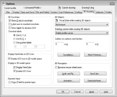
In the 3D Crosshairs section, you can specify the look of the 3D crosshairs. You can choose to show the Z axis (on by default) and to label the axes. If you show labels, you can customize them. You can also show labels for a Dynamic UCS.
In the Display ViewCube or UCS Icon section, you can decide when you want to see the UCS icon. Some people don't want it in 2D model space, for example, but want it on for 3D work. You can also decide if you want to display the ViewCube when you are in 3D model space.
In the Dynamic Input section, you can display a Z field for pointer input. If you leave this item unchecked (the default), you can always display it by simply entering a comma and a third (Z) coordinate value.
In the 3D Objects section, you can set a separate visual style while you are creating 3D solids and extruded solids and surfaces. By default, the current visual style (ByViewport) is used, but you may want a special one for the creation process.
The Deletion Control While Creating 3D Objects drop-down list sets the DELOBJ system variable, which I discuss in Chapter 24.
The two text boxes under the Isolines on Surfaces and Meshes label control the SURFU and SURFV system variables, which I cover in the "Creating Plane Surfaces" section of Chapter 23. These set the default number of isolines on surfaces and meshes.
Note
Click the Tessellation and Mesh Primitive buttons to change the settings used to convert objects to 3D mesh objects and to create mesh primitive objects (AutoCAD only). For more information, see Chapter 24.
The 3D Navigation section contains settings related to 3D Navigation. You can reverse the direction that you scroll the mouse wheel to zoom in and out to match other software that may be the opposite of AutoCAD. You can set walk and fly settings, ViewCube, SteeringWheels, and animation settings here. I cover these settings in Chapter 22.
The Selection tab contains settings that control how you select objects. This tab is shown in Figure A.13.
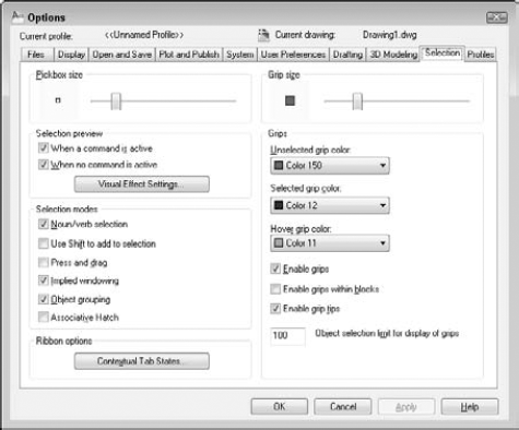
The options in the Selection Modes and Pickbox Size sections, which customize object selection, are discussed in detail in Chapter 9. The options in the Grips and Grip Size sections are covered in Chapter 10.
The Selection Preview section lets you specify what happens when you pass the cursor over an object to see what object you would select if you clicked your mouse. By default, objects are highlighted and you can customize the look of this highlighting. I cover this section in Chapter 9.
Note
The Ribbon Options section lets you control the display of ribbon tabs associated with selecting a specific type of object or starting a specific command. For more information, see Chapter 33.
The Profiles tab, shown in Figure A.14, enables you to create user profiles. AutoCAD LT does not offer this feature (or the tab). A profile is a group of settings, most of which you set in the Options dialog box. It can include all settings that are saved in the Windows Registry. Settings that are saved in the current drawing (indicated in the Options dialog box by the blue drawing marker) are not included in a profile. If you share your system with someone else and you each want to store different settings, or if you want different settings for different projects, you can create a profile and make it current when you open AutoCAD.
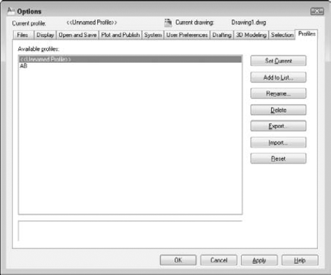
Whatever settings you create with the Options dialog box are automatically part of the default profile, which starts out with the unexciting name of Unnamed Profile. Here's how you create a new profile:
Click Add to List to open the Add Profile dialog box. Type in a profile name and description and click Apply & Close. This adds a new profile that is a duplicate of the current profile.
On the Profiles tab, click the new profile and choose Set Current.
Go through the other tabs and make the changes that you want. Be sure to click Apply on each tab.
Click OK to close the Options dialog box.
Whenever you make changes in AutoCAD settings that affect the Windows Registry, those changes become part of the current profile.
To use the profile or another profile, choose Application Button
Tip
To start AutoCAD with a specific profile, you can specify a profile by using a command-line switch, as explained in the next section. You can also export a profile (click the Export button) to share it with colleagues or use it on another computer. To use an exported profile, click the Import button on the Profiles tab of the Options dialog box.
When you choose the AutoCAD icon to open AutoCAD, Windows notwithstanding, you execute a statement similar to the one that old-timers once typed at the DOS prompt. This is called a command-line statement. By default, it looks something like c:Program FilesAutoCAD 2010acad.exe or c:Program FilesAutoCAD LT 2010acadlt.exe. Your exact command-line statement depends on where you installed AutoCAD or AutoCAD LT.
You can add parameters, called switches, to the end of this command line to control what happens when you start the program. Always add a space between the acad.exe or acadlt.exe command and a switch. Before any switch, you can add the name of a drawing to open that drawing. You need quotation marks around any path or drawing name that contains spaces. Table A.1 lists the available command-line switches and their functions.
Table A.1. Command-Line Switches
You can combine switches. For example, the following command-line statement opens the drawing "Union Hill Apts" in the front view and runs the setup script.
C:Program FilesAutoCAD 2010acad.exe "c:drawingsUnion Hill Apts.dwg" /v front /b setup
To change the command-line switch, follow these steps:
Right-click the shortcut to AutoCAD or AutoCAD LT on your desktop.
Choose Properties.
Click the Shortcut tab.
In the Target text box, add your switches to the end of the current command-line statement.
Click OK.
Every time you open AutoCAD, a configuration file is created. By default, this file (acad2010.cfg for AutoCAD or acadlt2010.cfg for AutoCAD LT) is an ASCII file containing mostly hardware-configuration information for your mouse and digitizer.
If you use multiple pointing devices — for example, a large and a small digitizer — you may want to create more than one configuration file to make it easy to switch from one configuration to another.
You should not edit the configuration file; instead, let AutoCAD create it for you. The problem is that AutoCAD assumes one configuration file and overwrites the previous one whenever you make changes that affect the file — such as adding a pointing device.
Remember that you can use the /c command-line switch to specify a configuration file. To create a new file, follow these steps:
Use Windows Explorer to back up your current configuration file under a new name, such as
acad2010-orig.cfg.Note
To find the location of
acad2010.cfg, choose Application ButtonOpen AutoCAD and make the pointer change that you want on the System tab of the Options dialog box. (If you're installing a new digitizer, follow the manufacturer's instructions to install the digitizer.) Click OK.
Close AutoCAD.
In Explorer, find the new
acad2010.cfgfile that AutoCAD created. Change its name, using something meaningful, such asLargeDigitizer.cfg.If you want to keep the original
acad2010.cfgfile, change its name back toacad2010.cfg.
You now have two configuration files. (You can create more if you want.) To use them, you can change the command-line switch as needed, but there's an easier way, as explained in the next section.
This appendix has discussed three different ways to create session configurations:
Profiles
Configuration files
Command-line switches
You can use command-line switches to specify a profile and a configuration file, as well as to configure AutoCAD in other ways, such as opening a drawing with a certain template or running a script file when you open a drawing.
If you regularly use these features, you should create multiple configurations to make it easy to open AutoCAD the way that you want by doing the following:
Create the profiles and configuration files that you need.
Make as many shortcuts as you need.
Note
To create a new shortcut, use Explorer to find
acad.exe(usually inAutoCAD 2010) oracadlt.exe(usually inAutoCAD LT 2010). Right-click it and choose Create Shortcut from the menu. Drag this to your desktop and rename it.Change the command-line switches to specify the profiles and configuration files that you want, and add any other command-line switches that you need.
For example, here are command lines for two separate AutoCAD desktop shortcuts. You could make similar command lines for AutoCAD LT.
C:Program FilesAutoCAD 2010acad.exe /t acad /nologo
C:Program FilesAutoCAD 2010acad.exe /p steve /c steve.cfg /t arch
The first command-line statement opens drawings by using the acad.dwt template and doesn't display the logo. It also uses the default profile and configuration file.
The second command-line statement opens drawings by using the arch.dwt template and displays the logo. It also uses the steve profile and the steve configuration file.
You could also have each configuration run different script files. This technique takes some time to set up, but after it's done, it saves you time and reduces errors each time you open AutoCAD or AutoCAD LT.
Windows supports many printers. To add a printer supported by Windows, choose Start
The Windows system printer drivers are great for small desktop printers because that's their intended use, but they aren't optimized for pen plotters or large-format plotters. For this purpose, AutoCAD and AutoCAD LT come with non-system drivers. These drivers are specially designed for CAD and usually provide you with more options than if you choose the default Windows system printer settings. You cannot use them with other Windows applications.
To configure a non-system plotter, use the Plotter Manager. (You can also use the Plotter Manager to create custom settings for a system printer.) You have several ways to open the Plotter Manager:
From Windows, choose Start

From within AutoCAD or AutoCAD LT, choose Application Button
From within AutoCAD or AutoCAD LT, choose Application Button
The Plotter Manager has a wizard (double-click Add-A-Plotter Wizard) that guides you through the process of configuring a printer. Follow the instructions on each page, which vary based on your previous choices.
For more information, see the "Use Plotters and Printers" section in the Help system. On the application title bar, click the Help button and then choose Driver and Peripheral Guide from the Contents tab.
During the process of configuring a plotter, you can import a PCP or PC2 configuration file that was created with an earlier release.
The result of configuring a plotter is a plotter configuration file that has a filename extension of .pc3. These PC3 files are saved in the Plotters folder. (To find the PC3 files, choose Application Button
At the end of the Plotter Manager Wizard, you can click Edit Plotter Configuration to change the default settings for your plotter. You can also click Calibrate Plotter to test that the plotter plots accurately.
You can edit a plotter configuration and change its original settings. You can access the file in several ways:
As just mentioned, click Edit Plotter Configuration at the end of the Plotter Manager Wizard.
From within AutoCAD or AutoCAD LT, choose Application Button
From Windows Explorer, double-click a PC3 file. The location of the PC3 files is listed on the Files tab of the Options dialog box, under Printer Support File Path
A PC3 file is not an ASCII file. When you open a PC3 file, you see the Plotter Configuration Editor dialog box, as shown in Figure A.15.
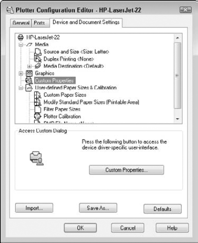
Figure A.15. The Plotter Configuration Editor is the place to change settings related to your printer or plotter.
The General tab lists basic information about the plotter. This tab does not contain any options that you can configure, although you can add a description of the plotter and its settings.
The Ports tab enables you to choose to plot through a port (the usual situation), plot to a file, or use AutoSpool to plot to a printer spooler. If more than one port is available, then you can choose and configure the port.
The Device and Document Settings tab contains plotting options, depending on your plotter.
As you select an item from the top part of the Plotter Configuration Editor, the appropriate options become available on the bottom of the dialog box. You can configure the following (your plotter will probably show different options):
Media. The source and size of the paper.
Physical Pen Configuration. Correction for filled areas (for extra accuracy), pen optimization for faster plotting, pen color, pen speed, and pen width.
Graphics. Color depth (the number of colors), monochrome, resolution, and dithering.
Custom properties. Vary by plotter. For Windows system printers, you might find settings such as draft printing and grayscale (for color printers).
Initialization Strings. Rarely used nowadays. If you're plotting to an unsupported plotter, you may be able to prepare the plotter for printing, set options, and restore the plotter to its original state by using ASCII text initialization strings.
User-Defined Paper Sizes and Calibration. Calibrate a plotter, create custom paper sizes, and change the plottable area of standard paper sizes. You can filter out unused paper sizes by unchecking sizes that you don't want to display. You can choose to apply the changes only to the current plot or to the configuration file.
When you finish making changes, click OK to save the changes to the PC3 files. You can also click Save As to create a new PC3 file. Click Default to return all settings to their defaults.