
Although the ribbon and menu are designed to be useful for most people, the whole point of customization is that everyone has different needs. You can probably draw more efficiently and faster by customizing the user interface to suit your own individual requirements. Not only can you add commands, but you can also add items consisting of a series of commands that run like a macro. If you're using AutoCAD, you can even add AutoLISP routines. You may want to create specialized items that are used only for one drawing — for example, to help clients view a drawing. User interface customization includes the ribbon, menus, mouse or puck buttons, toolbars (covered in Chapter 29), rollover tooltips, shortcut menus, image-tile menus, keyboard shortcuts, temporary override keys, the double-click function, and the Quick Properties palette. The only limits are your imagination and the time that you can devote to customization.
The AutoCAD or AutoCAD LT user interface is contained in a file that you don't edit directly; instead, you use the Customize User Interface, or CUI, Editor to modify the menu.
Note
In AutoCAD 2010 and AutoCAD LT 2010, the entire menu file is in a packaged file format. Starting with AutoCAD 2006 and AutoCAD LT 2006 through AutoCAD 2009 and AutoCAD LT 2009, the menu file was in XML format. If you're upgrading from a release earlier than AutoCAD 2006 or AutoCAD LT 2006, you'll see that in place of the MNU, MNS, and MNC files is one file, acad.cuix or acadlt.cuix. Instead of editing the file directly, you use the Customize User Interface Editor. The new packaged file format also includes all the bitmap image files used for the commands in the customization file that you create that are not stored in a DLL file.
The main customization file is acad.cuix in AutoCAD, and acadlt.cuix in AutoCAD LT. You can either customize this file or load another customization file.
Warning
Don't even think about customizing until you've backed up at least acad.cuix or acadlt.cuix. It is possible to corrupt the customization file.
Tip
If you get into a problem with your menu, then you can restore your most recently saved menu by right-clicking the customization group's name at the top of the Customizations In pane and choosing Restore ACAD.CUIX (or ACADLT.CUIX). You can also go back to the original menu that came with the program by right-clicking the customization group name and choosing Reset ACAD.CUIX (or ACADLT.CUIX). Another way to find the original customization file is to look in C:Program FilesAutoCAD 2010 (AutoCAD LT 2010)UserDataCacheSupport (if you used the default installation location).
In addition to the main customization file, AutoCAD and AutoCAD LT use these other files:
custom.cuix. This file is specifically meant to be used for your menu customization. It is a partial customization file, which means that you use it to add on to the main customization file. For example, you can add a toolbar and a menu that you use with the regular menu.acad.mnroracadlt.mnr. This file contains the bitmap images used by the commands in the customization file, such as toolbar icons and icons on ribbon panels, but stored in a special way that allows AutoCAD to load them faster.acad.mnl. This file contains AutoLISP routines used by the menu and is automatically loaded when the menu is loaded (AutoCAD only).
You can create your own full (main or enterprise) or partial customization files, using any name that you want. You'll have the best results if you place all your customization files in the same folder as the main customization file.
Note
To find the location of acad.cuix or acadlt.cuix, choose Application Button
There are two types of customization files: partial and full. A partial customization file usually has only one or two ribbon panels, menus, or toolbars. You can then load this partial customization file along with your main customization file. If your customization file consists of simply adding a few items, then you may want to create a partial customization file and add it to your current main customization file. In this way, you don't need to alter the customization in your main customization file. While the customization in the main customization file is not altered, a reference to your partial customization file is added to the main customization file, though, so it is loaded when the main customization file is loaded.
On the other hand, you may also want to have complete alternate interfaces, in which case you can customize the main customization file. Perhaps two different people work on one computer and have different customization needs. For example, you may find it useful to have one customization file for architectural drawings, another for mechanical drawings, and a third for electrical schematics.
Using your own customization file is a good way to keep the original file safe, in case you want to go back to it. Generally, you start by making a copy of the default main customization file, acad.cuix or acadlt.cuix.
You can copy a customization file (or any file, for that matter) in Windows Explorer. Right-click the file and choose Copy. Then right-click in any blank space in the Explorer window and choose Paste. The new file appears at the bottom of the list of files. Click the file to select it, and then click it again to change its name. Enter the new name, and then press Enter.
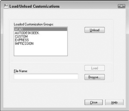
Each loaded customization file must have a unique name. If you want to work with your own customization file, you first need to unload the current customization file. Use the CUILOAD command on the command line both to unload and load a customization file. The Load/Unload Customizations dialog box opens, as shown in Figure 33.1. Choose the customization file that you want to unload, and click Unload.
To load a customization file, follow these steps:
In the Load/Unload Customizations dialog box, choose the current customization file and click Unload.
Click the Browse button.
Navigate to and select the customization file you want to load. Click Open.
In the Load/Unload Customizations dialog box, click Load.
Click Close to close the dialog box.
Tip
You can determine the current main customization file by choosing Application Button

Choose Manage tab
In the Customizations In pane, the top drop-down list should show All Customization Files or Main Customization File. The top item in the pane lists the current main customization file. It may still show the customization file that you unloaded; in that case, right-click it and choose Rename. Enter the name of the customization file that you loaded, and press Enter to match the customization group name to the filename.
By default, when you start AutoCAD or AutoCAD LT, the last customization file that you used, the name of which is stored in the Windows registry, is loaded. If you want to use a new customization file while in AutoCAD or AutoCAD LT, unload the current customization file and load the new one.
You can use the Custom partial customization file that comes with AutoCAD (or AutoCAD LT) or create your own partial customization files. To create a new partial customization file, follow these steps:

From the drop-down list, choose Save As. Enter a name for the new file in the Save As dialog box. Make sure that you use a name that is different from all other customization files.
To use the file, go to the Customize tab and choose Main Customization File from the drop-down list in the Customizations In pane. Then click the Load Partial Customization File button to the right of the drop-down list. In the Open dialog box, locate the partial customization file and click Open.
Choose Main Customization File again from the drop-down list. You should now see the new file listed under the expanded Partial Customization Files item.
You can load more than one partial customization file along with the main customization file. For example, you might have one partial customization file for 2D work and another for 3D work; sometimes, you might want both of them.
You can load and unload partial customization files in two ways:
Use the CUILOAD command as explained in the previous section.

After you have loaded a partial customization file, check to make sure that it has been loaded. In the Customize User Interface Editor, choose Main Customization File from the top drop-down list. Expand the Partial Customization Files item in the Customizations in Main File pane, and make sure that your partial customization file is listed.
To unload a partial customization file, use one of these methods:
Use the CUILOAD command. Follow the instructions for unloading a main customization file, described in the previous section.
In the Customize User Interface Editor, right-click the file and choose Unload.
You can also move customization items between customization files, using the Transfer tab of the Customize User Interface Editor. You can transfer items from a loaded file to any customization file. You can also transfer items between partial customization files or between a main customization file and a partial one.
When you display the Transfer tab, the main customization file is listed in the left pane. To open another file, click the Open Customization File button in the right pane, choose the file that you want to use, and click Open.
In each pane, expand the element that you want to transfer. For example, if you want to transfer menus, expand the Menus item on each side. You then see the actual menus in each file that is listed. To transfer an item, drag it from one pane to the other. Make sure that you are dragging to the same type of item, that is, menu to menu or ribbon panel to ribbon panel.
When you're done, click OK to close the Customize User Interface Editor.
When you first start customizing a customization file, the process may seem overwhelming. However, even small changes can be very useful. Start simple and take it from there.
Customization files include many types of customizable content, as follows:
Toolbars let you choose commands from buttons and change settings from drop-down lists. I discuss customizing toolbars in Chapter 29.
Ribbon panels also let you choose commands from buttons, as well as specify settings using special controls. You can add or remove buttons, drop-down lists, and subpanels.
Ribbon tabs let you organize and display ribbon panels and the ribbon.
Ribbon contextual tab states allow you to display ribbon tabs based on a set of predefined states that the drawing editor might be in (an object being selected or a command being active).
Note
Ribbon contextual tabs are not new in AutoCAD 2010 or AutoCAD LT 2010, but the ability to control which ribbon tabs are displayed with the predefined contextual tab states is.
Menus are the drop-down lists at the top of your screen in the AutoCAD Classic or AutoCAD LT Classic workspace.
Keyboard shortcuts come in two varieties. Shortcut keys, such as Ctrl+C for the COPYCLIP command, which execute commands and temporary override keys.
Temporary override keys (which I explain how to use in Chapter 4) are another kind of keyboard shortcut, but they temporarily override settings, such as Object Snap and Ortho Mode.
Shortcut menus appear when you click the right mouse button. (See Chapter 3 and Appendix A for more information on right-clicking.)
Double-click actions control what happens when you double-click an object.
The Quick Properties palette shows the properties of objects that you select. You can control which properties appear on this panel. Rollover tooltips are similar, but they appear when you hover the cursor over an object, without selecting it.
Tablet menus control the menu that can be overlaid on a digitizing tablet.
Tablet buttons control the multiple buttons on a puck that you use with a digitizing tablet.
The screen menu is AutoCAD's original menu that used to appear at the right side of your screen. (This section does not exist in AutoCAD LT.) By default, it is not displayed, but it still exists in the customization file. In AutoCAD, you can display it by choosing Application Button
The best way to start customizing the user interface is to look at a ribbon panel and its corresponding representation in the Customize User Interface Editor. Each type of user interface content has its own unique features, but certain features apply to most, if not all, menu types.
Figure 33.2 shows the AutoCAD Draw panel of the Home tab in the 2D Drafting & Annotation workspace.
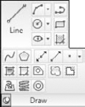
Figure 33.2. The AutoCAD Draw panel of the Home tab as it appears in the 2D Drafting & Annotation workspace.
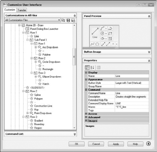
Figure 33.3 shows the same panel as it is displayed in the Customize User Interface Editor. Compare this list to the panel shown in Figure 33.2.
In Figure 33.3, the LINE command is selected, and the right side of the Customize User Interface Editor shows the information relating to that command. Note that commands have the following elements:
Name. The name is what you actually see on the ribbon panel when the button is set to display labels. When working with menus, the ellipsis (...) after the name provides a visual cue that this item opens a dialog box. The ampersand (
&) places an underscore under the following letter. You can then type the letter to execute the menu item (instead of clicking the menu item with your mouse). The mouse buttons, tablet buttons, tablet menus, shortcut menus, and double-click actions do not display the name, but the name is required.Button Style. This controls the direction of the icon and its label, if the label is displayed, and its size. This property is unique to commands on ribbon panels and Quick Access toolbars, but it does not change the display of the button on the Quick Access toolbar.
Group Name. This is used to group commands together when placed on a drop-down list with grouping enabled. This property is unique to commands on ribbon panels and Quick Access toolbars.
Command Name. This is the name of the command. Usually, it's the same as the display name.
Description. For ribbon panels, drop-down lists, shortcut menus, and toolbars, the description appears on the status bar when you hover the cursor over the menu item or button. The other menu elements don't use the description, although some of them let you enter one.
Extended Help File. You can create an expanded tooltip that contains instructions for using the command. The expanded tooltip appears when you hover the cursor over a command on a toolbar, ribbon panel, or Quick Access toolbar. Here you would put the filename and ID for that content.
Command Display Name. This is text containing the name of the command.
Macro. The macro is the command that the item executes. In the next section, I explain how to write menu macros. This can be a simple command, any group of commands, or an AutoLISP expression if you're using AutoCAD. The following conventions are recommended:
Add an apostrophe (
') before commands that can be used transparently. (Otherwise, the commands won't work transparently when chosen from the menu.)All other commands start with
^C^C, which is equivalent to pressing Esc twice. This cancels any other command that may be active. One Esc is generally enough, but occasionally two are necessary. (In rare situations, more might be needed.)The underscore is used before each command. This allows translation of the command into other languages. For example, your menus would automatically be translated into the equivalent French command in France!
Tags. You can add keywords to facilitate searching for the command in the application menu's search box.
KeyTip. This character sequence is used to access ribbon tabs and panels, and the Quick Access toolbar from the keyboard. Press Alt to display the keytips for the items on the ribbon, application menu, and Quick Access toolbar. You see keytips only when the menu bar is not displayed; otherwise, Alt allows you to access the menu bar by using the keyboard.
Tooltip Title. This controls the alternate title displayed for the command if it is the most recent command used from a drop-down list. This property is unique to commands on drop-down lists which are displayed on a ribbon panel or Quick Access toolbar.
Key(s). Shortcut keys and temporary override keys have a Key item, which specifies which key combination you use to execute the macro.
Element ID. This is a unique identifier that the program assigns automatically. In previous releases, it was used to link drop-down list items and toolbar buttons to their status bar help, and to link a keyboard shortcut to a menu item. You can still use this identifier for programming purposes. You cannot change the ID of an existing command, but you should add one for new commands that you create.
Images. Ribbon and toolbar buttons and some menu items have images. Most people use only the small image, but you can specify large images on the Display tab of the Options dialog box (Application Button
Drop-down and shortcut menus (the entire menu, not their items) also have aliases that you use when referring to the menu. You can add an alias by clicking the Ellipsis button to the right of the alias item.
Note
In Windows XP, by default, the underscores appear only if you access the menu by using the keyboard. To access a menu, press Alt and the underscores appear. Then type the underscored letter to open the menu. To choose a menu item, type its underscored letter. To disable this behavior and display the underscores all the time, choose Start
The macro is the heart of a custom command. To enter a macro, click the text box to the right of the Macro item and start typing. If your macro is long, click the Ellipsis button at the right of the text box to open the Long String Editor dialog box. You need to know a number of special characters and conventions in order to write menu macros. Table 33.1 lists some of the most common ones.
Table 33.1. Special Characters for Menu Macros
Description | |
|---|---|
| Equivalent to pressing Enter. The end of a line in a menu macro is also equivalent to pressing Enter. Use the semicolon when you need two returns at the end of a line, or when you want to indicate pressing Enter. Some commands, such as DTEXT/TEXT, also require a return to complete. You can also use |
Space | Similar to pressing Enter, except when entering text (to create a text object) that contains spaces (such as between words). Use between the command and its options. Note that you can even use a space on the command line for most commands. |
Pauses for user input, such as picking a point or typing a value. | |
| Used at the end of a line to continue the macro on the next line. |
| Placed at the beginning of a macro (before the |
| Indicates using the latest version of the command that follows in the macro. When ^R is not used, the oldest version of the command is used instead; this applies to commands that have changed from one release to another. For example, macros that use the LAYOUT and SOLIDEDIT commands work this way. |
| Turns on and off (toggles) the display of the menu macro, including menu prompts, on the command line. |
Note
Because the backslash pauses for user input, you cannot use it to specify a path, as in C:Program FilesAutoCAD 2010Support. Use the regular slash (/) instead.
Here is one macro from the Draw panel (hidden in a flyout) — Arc: Start, Center, Angle — that uses the backslash and the space:
^C^C_arc \_c \_a
Here's how this command works:
| Cancels any previous command. |
| Starts the ARC command (enables translation to another language version of AutoCAD or AutoCAD LT). |
Space | Equivalent to pressing the Spacebar, which is the same as pressing Enter after typing |
The backslash pauses the macro to let you specify a start point. | |
| Chooses the Center option, and enables translation to another language. |
Space | Equivalent to pressing the Spacebar, which is the same as pressing Enter after typing |
The backslash pauses the macro to let you specify a center point. | |
| Chooses the Angle option. Because this is at the end of the command, you don't need to specify a pause. The user specifies an angle and presses Enter, thus ending the command and drawing the arc. |
The backslash allows for only one input, except when used with the SELECT command. Therefore, you can use the SELECT command in menu macros to collect a selection set, and then use another command with the Previous option to act on the entire selection set. For example:
^C^Cselect move previous ;.1,0 ;
This macro cancels any existing command, starts the SELECT command, and lets you select as many objects as you want. You end object selection by pressing Enter. Then the macro automatically moves those objects to the right by 0.1 unit. Using the All selection option is another way to select more than one object in a menu macro.
Here are a few more examples of macros from earlier chapters:
You could place this macro on a drop-down list to make a selected polyline 0.1 unit wide:
^C^Cpedit w .1 ;
You could use the following macro to automatically draw four circles with the specified centers and radius.
^C^Ccircle 2,2 1.5 circle 6,2 1.5 circle 10,2 1.5 circle 14,2 1.5
You could use this macro to clean up a drawing. It uses CHPROP to select all the objects in a drawing, and it uses the Color option to change their color to ByLayer. Then it uses the LAYER command to freeze the layer named
no-plotand saves the drawing.^C^Cchprop all c bylayer -layer f no-plot qsave
You can customize the ribbon by adding or deleting buttons, rows, sub-panels, panels, and tabs. You can add existing commands or create a custom command. I discuss how to create custom commands for toolbars in Chapter 29; the process is the same for the ribbon. You add commands to a panel; you can't add commands to a tab. If you want a new panel, you add it and then add commands to it. Also, you can add a tab and add panels to that tab. After you create a tab, you can display it on the ribbon by assigning it to a workspace or a contextual tab state.
Ribbon panels are containers for commands, drop-down lists, and so on. They have a structure that enables you to lay out buttons so that they are easy to find and are well organized. Ribbon panels have the following elements:
Panel Separators. Each panel has a top portion that is visible by default, and an expanded portion that you see only when you click the panel's title bar at the bottom. You would place commonly used commands above the panel separator, and less common commands below it. Each panel automatically comes with a panel separator, indicated by the <SLIDEOUT> item in the Customizations In pane on the panel, so you don't need to add this element.
Rows. You place commands in rows. A panel can have rows above the panel separator, and additional rows below.
Subpanels. Sub-panels create separate sections in the ribbon panel. You use them to offset and group commands. For example, in the Draw panel (shown in Figures 33.2 and 33.3), Sub-Panel 1 follows the LINE command, setting it off by itself and grouping the rest of the commands in the ribbon panel. Sub-panels are optional.
Drop-down lists. You can add drop-down lists; they are used to organize multiple commands so they take up the space of one command.
Separators. You can add separators to separate commands. You can create two styles of separators: line and space. To set the type, select the separator and use the Properties panel to change the separator style.
Except for panel separators, you add these items by right-clicking in the appropriate location and choosing the item that you want. For example, you can right-click any row and add a new row, a new sub-panel, a new drop-down list, or a separator.
To add a command to a ribbon panel, follow these steps:
Choose Manage tab
Tip
To be able to see the tab that you want to work on, display that tab and then enter cui on the command line or in the dynamic input tooltip, instead of using the button on the Tools tab.
At the top of the Customizations in All Files section of the dialog box, expand the Ribbon item. Then expand the Panels item and the panel that you want to contain the command. Finally, expand the row that you want. Note that many of the panels have 2D and 3D versions; pick the one that you'll be working with.
Choose the command that you want to add from the Command List pane. (If necessary, display that pane by clicking the double-down arrow to the right of the Command List title.) You can choose an existing or a custom command. Chapter 29 explains more about how to use this pane, including how to find commands easily.
Drag the command to the desired row. If it isn't in the proper location within the row, drag it again to where you want it to be.
Tip
You can then click the panel and see a preview in the Panel Preview pane of the dialog box.
Click Apply to apply the change. You can move the Customize User Interface Editor to see if you like the result.
Click OK to close the Customize User Interface Editor.
Tip
You can copy an entire toolbar to a ribbon panel by right-clicking a toolbar in the dialog box and choosing Copy to Ribbon Panels. You can use this technique to convert custom toolbars that you created to ribbon panels.
Note
AutoCAD 2008 and AutoCAD LT 2008 allowed you to customize the dashboard panel by creating or modifying control panels. AutoCAD 2009 and AutoCAD LT 2009 did not allow you to migrate your control panels to the ribbon, but AutoCAD 2010 and AutoCAD LT 2010 do. You migrate a control panel by clicking Open Customization File on the Transfer tab, and then opening the CUI file that contains the control panels you want to migrate. Expand the Dashboard Panels item and right-click the control panel to migrate and choose Copy to Ribbon Panels. Click Yes. Expand the Ribbon and Panels item, and drag the converted control panel to the Panels item of one of the loaded customization files.
You may want to create your own ribbon panel. You start by creating the ribbon panel and adding commands to it. Then you add the panel to a tab.
To create a ribbon panel, follow these steps:
Choose Manage tab
At the top of the Customizations in All Files pane, expand the Ribbon item and right-click the Panels item and choose New Panel. A new panel appears, selected.
Enter a name for the panel and press Enter.
You can now add commands to the panel, as described previously.
When your new ribbon panel is complete, drag the panel to the desired tab. You may find it helpful to collapse the Command List pane first by clicking its double arrows.
At the top of the Customizations in All Files pane, expand the Ribbon item, right-click Tabs, and choose New Tab. A new tab appears, selected.
Enter a name for the new tab and press Enter. You now need to add ribbon panels to the tab.
Expand the Ribbon and Panels items and select the panels that you want to add to the tab. You can select more than one panel by pressing Ctrl as you click each new panel. You may find it helpful to collapse the Command List pane first by clicking its double arrows.
Right-click any of the selected panels, and choose Copy. This copies the panels,instead of moving them.
Right-click the new tab, and choose Paste.
Note
AutoCAD 2010 and AutoCAD LT 2010 allow you to assign ribbon tabs to contextual tab states. Contextual states identify the current state of AutoCAD, such as a command being active, the drawing editor being idle, or an object being selected. When talking about the ribbon, contextual states relate to a predefined list of commands that might be active or a specific type of object that is selected. Contextual tab states are not workspace specific like ribbon tabs are.
At the top of the Customizations in All Files pane, expand the Ribbon and Contextual Tab States items.
Expand the Tabs item and select the tabs that you want to add to the contextual tab state. You can select more than one tab by pressing Ctrl as you click each tab. You may find it helpful to collapse the Command List pane first by clicking its double arrows.
Click and drag any of the selected tabs and drop them on the contextual tab state in which you want to assign them.
Select one of the tabs you just assigned to the contextual tab state.
In the Properties pane, choose a display type for the ribbon tab under the Contextual Display Type field. You can select Merge to merge the ribbon tab with all displayed ribbon tabs, or choose to display it as its own ribbon tab by selecting Full.
Note
You can control the display behavior of context tabs with the Ribbon Contextual Tab State Options dialog box. To display the Ribbon Contextual Tab State Options dialog box, open the Options dialog box and click the Selection tab. Then click the Contextual Tab States button in the Ribbon Options section. (Choose Application Button
The Menus item of the Customize User Interface Editor controls the menus, which appear along the top of your screen in the AutoCAD or AutoCAD LT Classic workspace and drop down when you click them. You can customize existing menus or add your own menu to the main customization file. You can also create a partial customization file with one or more menus. Adding a command to a menu is very similar to adding a command to a toolbar (see Chapter 29) or ribbon panel (see the discussion earlier in this chapter).
Here are the basic procedures for creating drop-down lists:
To add a menu, right-click the Menus item in the Customizations In pane and choose New Menu. The menu appears at the bottom of the list of menus. You can immediately edit the default name. Press Enter.
Note
The name of a menu appears as the menu title. Keep these fairly short to keep the menu titles from running into each other. Don't place spaces in menu title names — it becomes hard to distinguish where one menu ends and the next one starts.
To add a command (an item) to a menu, drag the command from the Command List pane to the menu's name. If you already have items on the menu, you can drag above or below an existing item. You can also duplicate an existing command on a menu: Right-click the item in the Customizations In pane and choose Duplicate. To make sure that all commands are available, choose All Customization Files or Main Customization File from the Customizations In pane drop-down list, and choose All Commands from the Categories drop-down list. For information on creating custom commands, see Chapter 29.
Tip
To find any command that you're looking for, use the Find Command or Text button at the top of the Command List pane. The Find and Replace dialog box opens. Enter some text and click Find Next. Commands also show a tooltip of their macro in the Command List pane. There's also a Search Command List text box at the top of the Command List pane. You can type in text to display only matching commands in the list.
To add a separator below any item, right-click that item and choose Insert Separator from the shortcut menu. The separator helps to organize a menu into logical sections.
To delete an item, right-click the item and choose Remove. Click Yes in the confirmation message box.
Note
You can display the menu bar by setting the system variable MENUBAR to a value of 1 or by clicking the Customize button on the right side of the Quick Access toolbar and choosing Show Menu Bar.
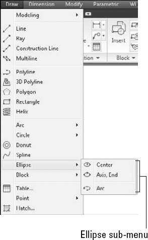
Submenus help you to organize your menu so that related commands stay together. Figure 33.4 shows the Ellipse sub-menu on the Draw menu, as shown on the menu bar.
To add a submenu, right-click any menu item and choose New Sub-menu. Name the submenu the same way that you would name a regular menu. You also add commands to a submenu in the same way that you add commands to a menu.
STEPS: Customizing the Ribbon and Menu
If you haven't already done so, back up the menu files. (These are the
acad.cuix,acad.mnr, andacad.mnl, oracadlt.cuixandacadlt.mnrfiles.) You use the backup files at the end of this exercise to undo the changes you made to the main customization file.Warning
Don't continue with this exercise until you've completed Step 1. If you're working on someone else's computer, ask permission before doing this exercise. To find the location of your menu files, choose Application Button
Open a drawing by using the
acad.dwtoracadlt.dwttemplate.The workspace should be set to 2D Drafting & Annotation. If it isn't, click the Workspace Switching button on the status bar and choose 2D Drafting & Annotation.
Display the Home tab. Click the Modify panel's title to expand the panel. Notice the Set to ByLayer button at the top left of the expanded panel. This executes the SETBYLAYER command. You would like to have this command more easily accessible and on the Layers panel. Note that there's room for it on the right side. You can't put a single command in a partial customization file, so you need to change the main customization file.
Type cui

In the Customizations In pane, expand the Ribbon and Panels items, and then expand the Home – Layers item. Expand Row 1. You want to place the SETBYLAYER command after the
Layer, Layer Offcommand, which displays as theOffitem under the row.To find the command, click the Find Command or Text button to the right of the All Commands drop-down list. (The command is not listed under SETBYLAYER.) In the Find and Replace dialog box, enter setbylayer in the Find What text box and click Find Next. The
Change to ByLayeritem highlights in the Command List and you can see the Properties panel of the item as well, which shows the correct command. Close the Find and Replace dialog box.Drag the
Change to ByLayercommand from the Command List pane to beneath theOffitem in the Customizations In pane. If it pops to the top of Row 2, drag it back down again.Click Apply and wait for the customization files to save your changes. Drag the dialog box down so that you can see the Layers panel. You should now see the SETBYLAYER command at the top right of the Layers panel.
From the drop-down list next to the Create a New Customization File button you clicked, choose Save As. In the Save As dialog box, enter ab2 in the File Name text box. Navigate to your
AutoCAD Biblefolder, and click Save.Choose All Customization Files from the drop-down list. Expand the Partial Customization Files item; you now see
AB2listed. Double-click theAB2item to expand it.Right-click the Menus item and choose New Menu. Enter AB2
To create a submenu, right-click the new
AB2menu and choose New Sub-menu. Enter &Special Edits
Name:
Move .1 rightDescription:Moves objects .1 unit to the rightMacro (after ^C^C):_select;\_move;_previous;;.1,0;;Element ID:AB_002aIn the Command List pane, choose the
Move .1 rightcommand, which is now highlighted, and drag it to theSpecial Editssub-menu. As you do this, you should see a small, left-pointing arrow. When you release the mouse button, the command should appear just below the sub-menu.To allow keyboard access, click the Name property for the
Move .1 rightcommand in the Properties pane and type & in front of the name.To create another custom command, again click Create a New Command in the Command List pane. In the Properties pane, enter the following:
Name:
Pedit .1Description:Sets polyline width to .1Macro (after ^C^C):_pedit;w;.1;;Element ID:AB_002bDrag the new command below the previous custom command.
To allow keyboard access, click the Name property for the
Pedit .1command in the Properties pane and type & in front of the name.To add an existing command to the main part of the menu (not the sub-menu), you need to display all the customization files. From the drop-down list under the Customizations In pane, choose All Customization Files. Then expand the Partial Customization Files item (at the bottom of the pane) to see the
AB2partial customization file. Expand Menus, thenAB2.From the Command List pane, choose
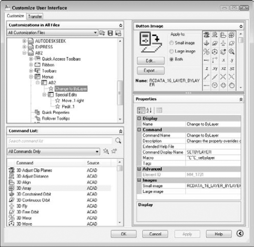
Change to ByLayer(the same command you used earlier in this exercise), and drag it up to theAB2item.Click the Save All Current Customization Files button in the Customizations In pane. Your pane should look like Figure 33.5.
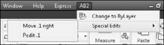
Choose AB2 on the menu bar and click the Special Edits sub-menu to expand it. It should look like Figure 33.6.
Note
If the AB2 menu doesn't appear, type cuiload
Open
ab33-a.dwgfrom the DVD. Save it asab33-01.dwgin yourAutoCAD Biblefolder.To try out the menu, choose AB2
Choose AB2
To try out the SETBYLAYER command that you placed in the Layers panel of the ribbon, click the Change to ByLayer button there. At the
Select objects:prompt, enter allEnter cuiload
Save your drawing.
Note
If some of the items don't work properly, edit the macros and try again.
The shortcut menus appear at the cursor. In addition to the Object Snap menu, which appears when you press Shift and the right mouse button, and the Grips menu, which appears when there is a hot grip and you right-click, there are several other shortcut menus. You access a shortcut menu by using the buttons on your mouse or puck. You can customize shortcut menus that are specific to a command or to a selected object. For example, if you right-click when a polyline is selected, the shortcut menu includes a Polyline Edit item. However, if you right-click when a spline is selected, the shortcut menu includes a Spline Edit item instead. Because the appropriate shortcut menu appears depending on the context, that is, the object that is selected, shortcut menus are context-sensitive. For this reason, they are sometimes called context menus. You can create your own context menus.
To create a shortcut menu, you specify the following:
Name. Although no name appears at the top of a shortcut menu (unlike a drop-down list), a name is required.
Description. The description is optional. The description would only appear if you turned the shortcut menu into a sub-menu, which you can do by dragging a shortcut menu in the Customize User Interface Editor to a menu.
Aliases. Aliases are used to reference the shortcut menu from elsewhere in the menu. Aliases are assigned automatically, but you need to add an alias in a special format if you create your own shortcut menu. To specify the alias, click in the Alias text box, and then click the Ellipsis button to open the Aliases dialog box. Click at the end of the current line and press Enter to start a new line. Enter the new alias in the format appropriate for that type of shortcut menu, and then click OK to close the dialog box. See the next two sections for a description of these formats.
Element_ID. An ID is required, but is assigned automatically. Change this if you want to refer to the shortcut menu in program code that you write.
You can create two kinds of context-sensitive menus: object menus and command menus. The context-sensitive menus work only for the main customization file.
Note
If you've turned on time-sensitive right-clicking, remember to hold down the right mouse button long enough to open the shortcut menu. See Chapter 3 for details.
Object menus
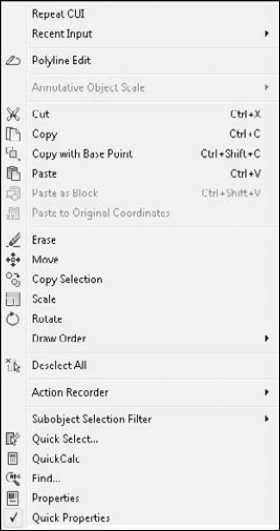
The Edit mode shortcut menu appears when you right-click in the drawing area while one or more objects are selected but no command is active, as shown in Figure 33.7. Note that this menu includes the most common editing commands.
You can create object menus that are specific to a type of object. You might want to add certain commands that you use often with that type of object. The commands that you add to an object menu are appended to the Edit mode shortcut menu so that the result is a menu that contains the Edit mode shortcut menu, plus any additional commands that you've added for that type of object.
To create an object menu, you must assign the menu an alias of either OBJECT_objectname (used when one object of a type is selected) or OBJECTS_objectname (used when more than one object of a type is selected). The object name is the DXF name of the object, with the following five exceptions:
BLOCKREF for a block insertion with no attributes
ATTBLOCKREF for a block insertion with attributes
DYNBLOCKREF for a dynamic block insertion with no attributes
ATTDYNBLOCKREF for a dynamic block insertion with attributes
XREF for an xref
Tip
To find out the object name of an object in AutoCAD, type the following on the command line: (cdr (assoc 0 (entget (car (entsel)))))
That's five closing parentheses at the end. AutoCAD then prompts you to select an object. As soon as you do, you see the object's name on the command line. See Chapters 34 and 35, which cover AutoLISP and Visual LISP, for an explanation of the parts of this AutoLISP expression. AutoLISP is not available for AutoCAD LT. In AutoCAD LT, you can create a drawing with only the one object whose name you want to know, and save it as a DXF file. Scroll down to the ENTITIES section in the DXF file to find the object's name. See Chapter 27 for more information about DXF files.
For example, to create an object menu that appears when one or more circles are selected, create an object shortcut menu with an alias of OBJECTS_CIRCLE. Open the Customize User Interface Editor and look at the shortcut menus in acad.cuix or acadlt.cuix for examples to help you create your own menus.
Command menus
The Command mode shortcut menu appears when you right-click in the drawing area while a command is active. You can create command menus that are specific to a command. The contents of the menu are appended to the Command mode shortcut menu; the result is a menu that contains the Command mode shortcut menu, plus any additional commands that you've added for that command. The default main customization file doesn't include any specific command menus. To create a command menu, you must assign the menu an alias COMMAND_commandname, where commandname is any valid command, including any custom or third-party command. After you name the menu, you can add commands to it that you would like to have available in the middle of the command just by right-clicking. Here are a couple of possibilities:
For the LINE command, you might want to add the PLINE command to the shortcut menu so that you can change your mind mid-command and create a polyline rather than a line. Of course, you can execute the PLINE command with one pick from the Draw toolbar, but the shortcut menu is closer.
For the ROTATE command, you might want to add the ALIGN command, in case you realize that you need to align an object instead of just rotating it.
You can add as many commands as your input device has buttons. To add a button, in the Customize User Interface Editor, right-click one of the items under the Mouse Buttons section, such as Click or Shift+Click, and choose New Button.
To add a command to a button, drag the command from the Command List pane to the mouse button section.
Note
You can customize the Mouse Buttons and Tablet Buttons sections for full customization files only, not for partial menus.
Click the Mouse Buttons Click section to see the default settings for up to 10 buttons. Button 1 is not listed, because it's always the pick button. If you have a number of buttons on your pointing device, you can leave these macros as they are or change them to suit your needs.
Tip
You can pan and zoom with the IntelliMouse. The MBUTTONPAN system variable controls the middle (third) button or wheel on your pointing device. By default, it's set to 1, which supports panning and zooming. Set it to 0 to support the definition in the customization file.
The following exercise shows you how you can customize even a two-button device. Because you may be working on someone else's computer, the exercise undoes the customization at the end.
STEPS: Customizing the Buttons Menu
Back up your menu files. (By default, these are
acad.cuixfor AutoCAD andacadlt.cuixfor AutoCAD LT.)Warning
Don't continue this exercise until you've completed Step 1. If you're working on someone else's computer, ask permission before doing this exercise.
To make a duplicate of
acad.cuixoracadlt.cuix, right-click the file in Windows Explorer and choose Copy from the shortcut menu. Right-click again and choose Paste. Windows places a copy of the file in the same folder.Note
To find the location of your menu files, choose Application Button
Click the copied menu file and rename it
ab1.cuix(that's the number 1, not the letter L). Press Enter.Open a drawing by using any template. On the command line or in the dynamic input tooltip, type cuiload
Click Browse. In the Select Customization File dialog box, choose
ab1.cuixand click Open. Back in the Load/Unload Customizations dialog box, click Load. All of your menus and toolbars reappear. Click Close to return to your drawing.On the command line or in the dynamic input tooltip, type cui
If you use a system mouse, double-click the Mouse Buttons item, and then double-click the Ctrl+Click item. If you use a digitizing tablet or other non-system input device, double-click Legacy, double-click Tablet Buttons, and then double-click the Ctrl+Click item. Click the Button 2 item (the right mouse button on a two-button mouse).
In the Command List pane, click the Create a New Command button. In the Name text box of the Properties pane, enter Toggle Snap Mode
Note
If your menu doesn't list a button for Ctrl+Click, then right-click this item and choose New Button.
Find the new Toggle Snap Mode command in the Command List pane's list of commands and drag it to the Button 2 item. You should see a small left-facing arrow pointing directly to the Button 2 item.
Double-click Ctrl+Shift+Click in the Customizations In pane and click the Button 2 item. Again click the Create a New Command button in the Command List pane. In the Name text box of the Properties pane, type Toggle Ortho Mode
Find the new Toggle Ortho Mode command in the Command List pane's list of commands and drag it to the Ctrl+Shift+Click Button 2 item. You should see a small left-facing arrow pointing directly to the Button 2 item.
Click OK to return to your drawing.
Press and hold Ctrl and right-click the button. The Snap Mode button on the status bar turns on (highlighted in blue). Move your cursor around to verify that Snap is on. (If the cursor doesn't snap to points, then PolarSnap is on. Right-click Snap Mode on the status bar and choose Grid Snap On.)
Hold Ctrl+Shift and right-click the button. Ortho Mode turns on if it's currently off or turns off if it's currently on.
Hold Ctrl+Shift and right-click the button again to toggle Ortho Mode again.
To return to your original menu, enter cuiload
Again, try using Ctrl plus right-click and Ctrl+Shift+Right-click. The button no longer works as before. Instead, both key combinations open the Object Snap shortcut menu.
Don't save your drawing.
Image-tile menus are menus that contain slides. The image tile displays the contents of the slides. The main use of image-tile menus is to insert blocks. You could use tool palettes in the same way, and tool palettes are easier to create. I cover slides in Chapter 30 and tool palettes in Chapter 29. AutoCAD LT doesn't include any image-tile menus, but you can create them. Image-tile menus are not easy to create, and you can probably use a tool palette instead. They're an old menu technology. Before you create your own image-tile menus, you need to create the slides. In order that they fit into the image tiles properly, you should create a floating viewport that is 3 units wide by 2 units high (or any multiple thereof, to maintain the proportion), center the drawing so that it takes up most of the viewport, and create the slide. Then create the slide library, as explained in Chapter 30.
To create a new image-tile menu, follow these steps:
Open the Customize User Interface Editor.
Double-click the Legacy item in any menu to expand it.
Right-click the Image Tile Menus item and choose New Image Tile Menu.
Name the image-tile menu. The name will appear at the top of the dialog box.
Add a description if you want.
Add an alias. You will need to use this alias in the menu macro that displays the image-tile dialog box.
Either drag an existing command to the new image-tile menu, or create a custom command and drag that to the menu.
In the Slide Library text box, enter the slide library name. The slide library is the name of the SLB file that contains the slides.
In the Slide Label text box, enter the label that you want to appear in the image-tile dialog box, which should also be the name of the slide (SLD) file.
You display an image-tile menu from another menu. To display the 3D Objects menu (which is no longer available on the menu), AutoCAD used the following code:
$I=ACAD.image_3dobjects $I=ACAD.*
This special format swaps to the 3D Objects image-tile menu and displays it. The customization name (ACAD in the previous example) is not necessary if both the menu that you're referring to and the menu that you're placing the item on are the same. You can create a partial menu that displays an image-tile menu. Therefore, you need to add a menu item somewhere that displays your image-tile menu. For example, if your image-tile menu's alias is MyBlocks, you could use the following macro:
$I=MyBlocks $I=*
When you're done, click OK to close the Customize User Interface Editor. Choose the new menu item that references the image-tile menu, and the image-tile dialog box appears. AutoCAD or AutoCAD LT automatically creates the dialog box. If it has more than 20 items, AutoCAD or AutoCAD LT creates Previous and Next boxes as well. To use one of the images, choose it either from the listing or from the image tiles and click OK.
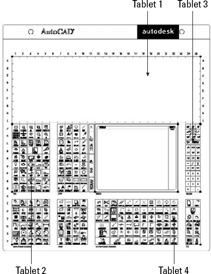
Tablet menus are straightforward. Figure 33.8 shows the default tablet arrangement. You can print out this tablet drawing; download tablet.dwg from www.autodesk.com/autocad-samples if you are using AutoCAD, or tablet_overlay.dwg from www.autodesk.com/autocadlt-samples if you are using AutoCAD LT, and compare it to the Tablet Menus item in the Legacy section. The entire first section, Tablet Menu 1, is left blank for you to configure. Although this menu section lists 25 rows and 25 columns, to match Tablet.dwg, use 9 rows and 25 columns. If you configure this menu area (using the TABLET command) to contain 9 rows and 25 columns, you can place your own macro in each of these boxes.
Note
For information on digitizing drawings and calibrating a tablet, including an exercise, see Chapter 16.
The syntax of the Tablet menu is very simple; you just need a name and the menu macro itself, although you can add a description.
Note
If you customize the Tablet menu, don't forget to also open tablet.dwg (for AutoCAD) or tablet_overlay.dwg (for AutoCAD LT). Make the corresponding changes, and print it out to overlay on your digitizer so that the drawing that you place on your tablet reflects the menu properly.
I don't cover the Screen menu because it's rarely used. If you're interested in customizing it, click the Screen Menu item under the Legacy item and click the Learn More about Screen Menus link. AutoCAD LT doesn't contain a Screen menu.
The Keyboard Shortcuts section has two subsections. Shortcut keys are a way to speed up your work. You can add keyboard shortcuts for commands that you use often. Temporary override keys are keyboard combinations that temporarily affect commonly used drafting settings, such as Object Snap and Ortho Mode. Note that keyboard shortcuts are different from aliases, which I explain in Chapter 29.
Tip
To print a list of shortcut keys or temporary overrides, click either section and click the Print button in the Shortcuts pane. You can also copy the list to the clipboard by clicking the Copy to Clipboard button. You can then paste the list into another document.
You can create a keyboard shortcut for any command. Before adding a keyboard shortcut for a command, check to see that one doesn't already exist. In the Customize User Interface Editor, expand the Keyboard Shortcuts item, and then the Shortcut Keys section to see the current list. To create a new keyboard shortcut, follow these steps:
Open the Customize User Interface Editor.
Expand the Keyboard Shortcuts item, and then the Shortcut Keys section.
From the Command List, drag a command to anywhere in the Shortcut Keys section. The location doesn't matter.
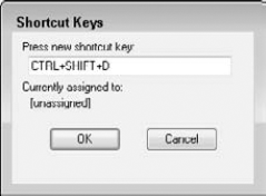
In the Properties pane, click the Key(s) text box, and then click the Ellipsis button to the right to open the Shortcut Keys dialog box, as shown in Figure 33.9.
Click in the Press New Shortcut Key text box and press the keyboard combination that you want to use on your keyboard. Table 33.2 lists the keys that you can use to create shortcuts. When you include a modifier, such as Ctrl or Ctrl+Alt, with another key, you need to hold down the modifier or modifiers as you press the key. If the keyboard combination is already assigned to another command, then you see that command below the text box. If you want, you can choose another combination, or keep the one that you chose, thus overriding the original shortcut.
Click OK to close the dialog box.
Click OK to close the Customize User Interface Editor. Try out your new keyboard shortcut!
Warning
You should not reassign the commonly used Windows shortcuts, such as Ctrl+C (to copy data to the Clipboard), Ctrl+V (to paste data from the Clipboard), and so on.
Table 33.2. Allowable Modifier and Key Combinations for Keyboard Shortcuts
Modifier | Key |
|---|---|
Ctrl | Any letter, number, or function key |
Ctrl+Alt | Any letter, number, or function key |
Shift | Any letter, number, or function key |
Shift+Alt | Any letter, number, or function key |
Ctrl+Shift | Any letter, number, or function key |
Ctrl+Shift+Alt | Any letter, number, or function key |
To remove a keyboard shortcut, right-click the shortcut in the Shortcut Keys section of the Customize User Interface Editor and choose Delete. Confirm the deletion.
Temporary override keys are keyboard combinations that toggle drafting settings, such as Object Snap settings. AutoCAD and AutoCAD LT define most of these for you, which is helpful, because the required macros are complex. Most of them also have keyboard combinations, but several don't, and you can easily add them. I explain how to use the existing temporary override keys in Chapter 4.
To see the current temporary override keys, open the Customize User Interface Editor. In the Customizations In pane, double-click the Keyboard Shortcuts item, and then the Temporary Override Keys item. Click any individual temporary override to see its properties in the Properties pane. Keyboard combinations can include function keys, or the Shift key with any letter, number, or function key. Some of the temporary overrides have two or three keyboard combinations, one for the left hand, one for the right hand, and perhaps a function key.
To create a new temporary override key, follow these steps:
In the Customize User Interface Editor, expand the Keyboard Shortcut item in the Customizations In pane.
Right-click the Temporary Override Keys item and choose New Temporary Override. Enter a new name for the temporary override. This name doesn't have to be unique. In fact, if you want a temporary override to have two keyboard combinations, you need to create two temporary overrides with the same name and macro.
In the Properties pane, enter a description, if you want one. Enter a macro in the Macro 1 (Key Down) text box. You can also enter a second macro in the Macro 2 (Key Up) box, which is executed when the keyboard combination is released. Most temporary overrides don't have a macro here; in this case, releasing the keys restores the settings prior to using the temporary override.
Tip
To make a copy of an existing temporary override (in order to add a second key combination), copy the existing macro and paste it into the Macro 1 (Key Down) text box of your new temporary override.
Click the Key(s) text box and then click the Ellipsis button. In the Shortcut Keys dialog box, click in the Press New Shortcut Key text box and press the keyboard combination that you want to use on your keyboard. The message below the text box indicates whether the keyboard combination is assigned. To accept the keyboard combination, click OK.
Note
Make sure that Caps Lock is off; otherwise, you won't be able to add a Shift to your temporary override.
You can now use your temporary override.
When you double-click an object, you usually see either the Properties palette or a specific dialog box that helps you edit that object. In Chapter 10, I explain this process. You can now customize what happens when you double-click an object.
To see the current double-click settings, open the Customize User Interface Editor and expand (or, appropriately, double-click) the Double Click Actions item. You see a list of objects. Expand any object and select the item beneath it. In the Properties pane, you see the current action, usually a command, in the Macro field.
For example, if you choose the Hatch object, the item beneath is labeled Hatch Edit, and you can see that it executes the HATCHEDIT command, which opens the Hatch Edit dialog box.
To change the double-click behavior for an object, follow these steps:
Start the CUI command to open the Customize User Interface Editor.
Expand the Double Click Actions item and expand an object type.
Select the item beneath the object.
In the Properties pane, change the current macro field and press Enter. You can also drag a command from the Command List.
Note
You can disable all double-click actions for editing by unchecking the Double Click Editing check box on the User Preferences tab of the Options dialog box (Application Button
The Quick Properties palette appears when you select an object. Rollover tooltips appear when you hover the cursor over an object without selecting it. You can customize which types of objects display the Quick Properties palette and rollover tooltips, and which properties appear, so that you see the information you need right away.
To specify which objects display the Quick Properties palette, open the Customize User Interface Editor and click the Quick Properties item in the Customizations in All Files pane. The right side of the dialog box changes to display a list of object types and properties. When no object is selected, you see only general properties that apply to all objects, such as color, layer, and linetype. Choose any object type, shown in Figure 33.10, to see additional properties that are specific to that object.
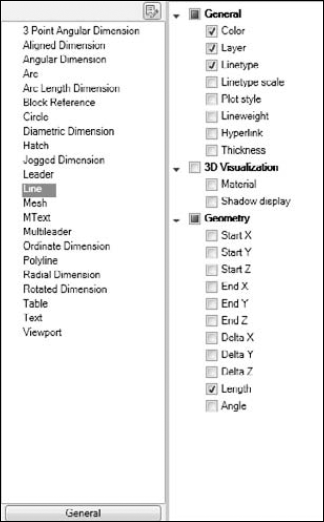
Figure 33.10. The Quick Properties item with the Line object selected shows a list of the properties that will display when you select a line.
The general properties listed when no object is selected in the object list apply to all objects, even objects not on the object list. For example, a spline is not on the list by default. Therefore, if you select a spline, you'll see only Color and Layer properties, which are the default general properties for all objects. By adding an object to the list, you can specify which additional properties you want to see for that object type.
To edit the object types, click the Edit Object Type List button at the top of the list of objects to open the Edit Object Type List dialog box. There you can check or uncheck objects. Click OK to close the dialog box. Then select the object from the object list and check the properties you want to see from the properties list on the right.
For any object, you can add or remove properties that will appear by selecting the object from the object list and checking or unchecking objects.
You can customize rollover tooltips in exactly the same way. Click the Rollover Tooltips item in the Customizations In pane and make the changes as just described for the Quick Properties palette.
In addition, you can synchronize the rollover tooltips with your Quick Properties settings, or vice versa. To do so, right-click the Quick Properties item, and choose Synchronize with Rollover Tooltips. You then have one of two choices:
Apply Rollover Tooltips Settings to Quick Properties palette.
Apply Quick Properties Settings to Rollover Tooltips.
Choose one of the options and click Apply.
In this chapter, you read about how to customize the user interface to suit your situation and speed up your everyday work. Specifically, you learned the following:
How to load and unload main and partial customization files
How to write menu macros
All about customizing the ribbon, menu bar, and drop-down lists
How to create custom shortcut menus
How to customize mouse and tablet buttons
How to create image-tile menus
About customizing the tablet menu
How to create keyboard shortcuts, including shortcut keys and temporary override keys
How to customize what happens when you double-click an object
How to customize the Quick Properties palette and rollover tooltips
This chapter ends Part VI, "Customizing AutoCAD and AutoCAD LT." Part VII challenges you to go farther in your customization of AutoCAD by starting to program with AutoLISP and Visual Basic for Applications.