
This time, the hardware setting is not very tricky since we just need two I2C chips to get the basic environment data for our weather station, while all the complexity is in the software settings, since we need at least a 3.13 kernel to manage the sensors and a complete software toolchain to talk with the Google Docs system!
Maybe this is not the case with you, but my BeagleBone Black runs a kernel version 3.8 where some drivers are missing. That's why I decided to install a new distribution based on kernel release 3.13 on an external microSD so that I do not have to modify the default on-board eMMC settings.
In any case, just to set up the hardware, I can use the current running kernel where I can enable the I2C bus named I2C1 with the following command:
root@beaglebone:~# echo BB-I2C1 > /sys/devices/bone_capemgr.9/slots
If everything works well, you should see the following kernel activities on your board:
part_number 'BB-I2C1', version 'N/A'
slot #7: generic override
bone: Using override eeprom data at slot 7
slot #7: 'Override Board Name,00A0,Override Manuf,BB-I2C1'
slot #7: Requesting part number/version based 'BB-I2C1-00A0.dtbo
slot #7: Requesting firmware 'BB-I2C1-00A0.dtbo' for board-name 'Override Board Name', version '00A0'
slot #7: dtbo 'BB-I2C1-00A0.dtbo' loaded; converting to live tree
slot #7: #2 overlays
omap_i2c 4802a000.i2c: bus 2 rev0.11 at 100 kHz
omap_i2c 4802a000.i2c: unable to select pin group
slot #7: Applied #2 overlays.
And a new device, /dev/i2c-2 should now be available:
root@beaglebone:~# ls -l /dev/i2c-2
crw-rw---T 1 root i2c 89, 2 Apr 23 20:23 /dev/i2c-2
Okay, now we can start adding the hardware to our BeagleBone Black and testing the connections with the current kernel.
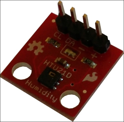
As a temperature and humidity sensor, I decided to use the device shown in the following image:
Note
The device can be purchased at the following link (or by surfing the Internet): http://www.cosino.io/product/humidity-sensor.
The datasheet of this device is available at http://dlnmh9ip6v2uc.cloudfront.net/datasheets/BreakoutBoards/HTU21D.pdf.
This device is very simple. The I2C connections are as follows:
|
Pin |
Temperature/humidity sensor pin |
|---|---|
|
P9.4 - Vcc |
+ |
|
P8.17 - CLK |
CL |
|
P8.18 - SDA |
DA |
|
P9.2 - GND |
- |
Tip
For further reading on the working of I2C bus, the reader can start with the Wikipedia article at http://en.wikipedia.org/wiki/I%C2%B2C.
Now, to verify the connections, we can use the i2cdetect command, as follows:
root@arm:~# i2cdetect -y -r 2
     0  1  2  3  4  5  6  7  8  9  a  b  c  d  e  f
00:          -- -- -- -- -- -- -- -- -- -- -- -- --
10: -- -- -- -- -- -- -- -- -- -- -- -- -- -- -- --
20: -- -- -- -- -- -- -- -- -- -- -- -- -- -- -- --
30: -- -- -- -- -- -- -- -- -- -- -- -- -- -- -- --
40: UU -- -- -- -- -- -- -- -- -- -- -- -- -- -- --
50: -- -- -- -- -- -- -- -- -- -- -- -- -- -- -- --
60: -- -- -- -- -- -- -- -- -- -- -- -- -- -- -- --
70: -- -- -- -- -- -- -- --
The string UU (or 40) at the 0x40 address means that the device is connected! However, it may happen that you get no UU strings at all due to some hardware issues regarding this device. In this case, we can use the i2cget command as follows in order to force an I2C activity on the device:
root@beaglebone:~# i2cget -y 2 0x40 0xe7 0x02
Okay, the device is connected. But if you get the following output, you must recheck the connections:
root@beaglebone:~# i2cget -y 2 0x40 0xe7
Error: Read failed
Tip
Note that you may need to disable the on-board pull-up resistors by clearing the soldered jumper on your sensor. In fact, the BeagleBone Black's I2C controller has the internal pull-up required by the I2C bus specifications, and under some circumstances, the pull-up on the sensor board may interfere with it.
As barometric sensor, I decided to use the device shown in the following image:

Note
The device can be purchased at the following link (or by surfing the Internet): http://www.cosino.io/product/barometric_sensor.
The datasheet of this device is available at http://www.epcos.com/inf/57/ds/T5400.pdf, and a useful application note is at http://www.epcos.com/inf/57/ds/T5400.pdf.
This device has two interfaces: I2C and SPI. However, since the previous device was an I2C one, I decided to use the same interface. So, the connections must be done as reported in the following table, leaving the other pins unconnected:
|
Pin |
Barometric sensor pin |
|---|---|
|
P9.4 - Vcc |
VCC |
|
P8.17 - CLK |
SCL/SCLK |
|
P8.18 - SDA |
SDA/MOSI |
|
P9.2 - GND |
GND |
Now, to verify the connections, we can use the i2cdetect command, as follows:
root@arm:~# i2cdetect -y -r 2
     0  1  2  3  4  5  6  7  8  9  a  b  c  d  e  f
00:          -- -- -- -- -- -- -- -- -- -- -- -- --
10: -- -- -- -- -- -- -- -- -- -- -- -- -- -- -- --
20: -- -- -- -- -- -- -- -- -- -- -- -- -- -- -- --
30: -- -- -- -- -- -- -- -- -- -- -- -- -- -- -- --
40: -- -- -- -- -- -- -- -- -- -- -- -- -- -- -- --
50: -- -- -- -- -- -- -- -- -- -- -- -- -- -- -- --
60: -- -- -- -- -- -- -- -- -- -- -- -- -- -- -- --
70: -- -- -- -- -- -- -- 77
As the preceding command shows, the string 77 (or UU) at the 0x77 address means that the device is connected! This time, the device should be detected without any issue. So, if you do not get the preceding output, please consider rechecking your hardware connections.
