
Capturing the data generated from light sensors is one of those satisfying and highly useful examples of physical computing. Some of you may have used light sensors—also known as CdS cells, photoresistors, and photocells—in your Arduino or Raspberry Pi projects. If so, this recipe will be a snap for you.
A photocell is a variable resistor, which in this case means that it varies its resistance according to the intensity of light exposed to it. The value of that variable resistance is turned into data, which in turn means the sensor functions as an effective measurement tool for ambient light. In this recipe, we show you how to read analog values captured from a light sensor using BoneScript along with an alternative Python script.
Rustle up the items in the list below for this recipe:
- Photoresistor (photocell): Nothing fancy for our purposes here. We're using one that costs less than USD $1.50 in many electronics stores such as SparkFun (http://bit.ly/1kwejIt).
- Resistor: 10,000 (10kΩ); brown/black/orange/gold bands
- 3x jumper wires: Easy to connect to breadboard.
- Breadboard.
- First, make sure your BBB is powered down, then wire up your breadboard. Here's what your wiring should look like:
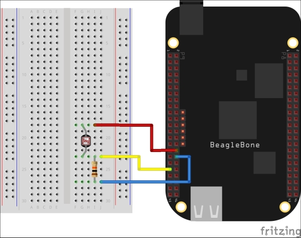
We wire this sensor up differently from the temperature sensor, so take care with the diagram. If you are reading this recipe and want to see color versions of the fritzing diagrams for better clarity on the wiring, you can find them online at http://bit.ly/1MP2UNo:
Light sensor: Plug the light sensor's wires into the breadboard, positioning the wires four or five slots apart from one another for easier wiring management.
Resistor: Plug the 10k resistor into the breadboard a couple of columns in front of the photocell with one end of the resistor aligned with the bottom wire of the sensor.
Voltage wire: Plug the red wire into the P9_32 slot on the BBB. This is one of the board's specially designated pins (labeled VDD_ADC) for 1.8V reference voltage, a low power source for analog sensors like this. The other end of the wire should be inserted into the breadboard aligning with the phototcell's top wire.
Ground wire: The blue wire is for ground (GND), and for this we will also use a special ground pin at P9_34 for 1.8V (GNDA_ADC).
Sensor pin: Plug one end of the yellow wire into P9_37 on the BBB, and the other end into a breadboard slot in front of the resistor. It should align with the bottom wire of the light sensor.
- Open up Cloud9 IDE at
http://192.168.7.2:3000. - Create a new file called
light_sensor.js, and paste the following BoneScript code into the window:var b = require('bonescript'); function lightSensor() { b.analogRead('P9_37', lightValue); } function lightValue(reading) { var millivolts = reading.value * 1800; console.log("Light output in millivolts: " + millivolts + " "); } setInterval(lightSensor, 1000); - Press the Run button to begin capturing light intensity readings. Your console output should look something like this. Your readings, of course, will vary according to the strength of your light source:
Light output in millivolts: 1387
Light output in millivolts: 1386
Light output in millivolts: 1159
Light output in millivolts: 608
Moving your hand over or close to the sensor should make the output numbers rise and fall based on how the light source hits the sensor. Notice that doing all this requires very few lines of code. So, let's take a quick look at what some of the parts of the script are doing
- Besides evoking the BoneScript library, the first section defines a
readfunction on a specific analog pin that we will reference on the BBB:var b = require('bonescript'); function lightSensor() { b.analogRead('P9_37', lightValue); } - In the next section, we define a function that determines how the sensor data being captured will be crunched. That data is expressed in millivolts and varies at a constant rate:
function lightValue(reading) {
  var millivolts = reading.value * 1800;
  console.log("Light output in millivolts: " + millivolts + "
");
}
The
Optional Python code
Besides the code above, you can also test your light sensor with a Python script available on our Github repository. There is a ReadMe file on the repo, but here are the basic steps:
- Download the Python code with the following command:
$ git clone
https://github.com/HudsonWerks/light-sensor.git
- Browse to the directory with the Python script and run it:
$ cd light_sensor
$ sudo python light_sensor.py
Your output should be very similar to what you saw in the BoneScript example.