
About the hardware, there are at least two major issues to be pointed out:
- Power supply: We have two different voltages to use due to the fact the water pump, the lamp, and the cooler are 12V powered, while the other devices are 5V/3.3V powered. So, we have to use a dual output power source (or two different power sources) to power up our prototype.
- Interface: The second issue is about using a proper interface circuitry between the 12V world and the 5V one in such a way that it doesn't damage the BeagleBone Black or other devices. Let me point out that a single GPIO of the BeagleBone Black can manage a voltage of 3.3V, so we need a proper circuitry to manage a 12V device.
As just stated, these devices need special attention and a dedicated 12V power line which, of course, cannot be the one we wish to use to supply the BeagleBone Black. On my prototype, I used a 12V power supplier that can supply a current till 1A. These characteristics should be enough to manage a single water pump, a lamp, and a cooler.
After you get a proper power supplier, we can pass to show the circuitry to use to manage the 12V devices. Since all of them are simple on/off devices, we can use a relay to control them. I used the device shown in the following image where we have 8 relays:

Note
The devices can be purchased at the following link (or by surfing the Internet): http://www.cosino.io/product/5v-relays-array
Then, the schematic to connect a single 12V device is shown in the following diagram:

Simply speaking, for each device, we can turn the power supply on and off simply by moving a specific GPIO of our BeagleBone Black. Note that each relays of the array board can be managed in direct or inverse logic by simply choosing the right connections accordingly as reported on the board itself, that is, we can decide that, by putting the GPIO into a logic 0 state, we can activate the relay, and then, turning on the attached device, while putting the GPIO into a logic 1 state, we can deactivate the relay, and then turn off the attached device.
The BeagleBone Black's GPIOs and the pins of the relays array I used with 12V devices are reported in the following table:
|
Pin |
Relays Array pin |
12V Device |
|---|---|---|
|
P8.10 - GPIO66 |
3 |
Lamp |
|
P8.9 - GPIO69 |
2 |
Cooler |
|
P8.12 - GPIO68 |
1 |
Pump |
|
P9.1 - GND |
GND | |
|
P9.5 - 5V |
Vcc |
To test the functionality of each GPIO line, we can use the following command to set up the GPIO as an output line at high state:
root@arm:~# ./bin/gpio_set.sh 68 out 1
Then, we can turn the relay on and off by just writing 0 and 1 into /sys/class/gpio/gpio68/value file, as follows:
root@arm:~# echo 0 > /sys/class/gpio/gpio68/value
root@arm:~# echo 1 > /sys/class/gpio/gpio68/value
The webcam I'm using in my prototype is a normal UVC-based webcam, but you can safely use another one that is supported by the mjpg-streamer tool.
Note
See the mjpg-streamer project's home site for further information at http://sourceforge.net/projects/mjpg-streamer/.
Once connected to the BeagleBone Black USB host port, I get the following kernel activities:
usb 1-1: New USB device found, idVendor=045e, idProduct=0766
usb 1-1: New USB device strings: Mfr=1, Product=2, SerialNumber=0
usb 1-1: Product: Microsoft LifeCam VX-800
usb 1-1: Manufacturer: Microsoft
...
uvcvideo 1-1:1.0: usb_probe_interface
uvcvideo 1-1:1.0: usb_probe_interface - got id
uvcvideo: Found UVC 1.00 device Microsoft LifeCam VX-800 (045e:0766)
Now, a new driver called uvcvideo is loaded into the kernel:
root@beaglebone:~# lsmod
Module                  Size  Used by
snd_usb_audio          95766  0
snd_hwdep               4818  1 snd_usb_audio
snd_usbmidi_lib        14457  1 snd_usb_audio
uvcvideo               53354  0
videobuf2_vmalloc       2418  1 uvcvideo
...
Okay, now, to have a streaming server, we need to download the mjpg-streamer source code and compile it. We can do everything within the BeagleBone Black itself with the following command:
root@beaglebone:~# svn checkout svn://svn.code.sf.net/p/mjpg-streamer/code/ mjpg-streamer-code
After the download is finished, we can compile and install the code by using the following command line:
root@beaglebone:~# cd mjpg-streamer-code/mjpg-streamer/ && make && make install
If no errors are reported, you should now be able to execute the new command as follows, where we ask for the help message:
root@beaglebone:~# mjpg_streamer --help
-----------------------------------------------------------------------
Usage: mjpg_streamer
  -i | --input "<input-plugin.so> [parameters]"
  -o | --output "<output-plugin.so> [parameters]"
 [-h | --help ]........: display this help
 [-v | --version ].....: display version information
 [-b | --background]...: fork to the background, daemon mode
...
Tip
If you get an error like the following it means that your system misses the convert tool:
make[1]: Entering directory `/root/mjpg-streamer-code/mjpg-streamer/plugins/input_testpicture'
convert pictures/960x720_1.jpg -resize 640x480!
pictures/640x480_1.jpg
/bin/sh: 1: convert: not found
make[1]: *** [pictures/640x480_1.jpg] Error 127
You can install it by using the usual aptitude command:
root@beaglebone:~# aptitude install imagemagick
Okay, now we are ready to test the webcam. Just run the following command line and then point a web browser to the address http://192.168.32.46:8080/?action=stream (where you should replace my IP address 192.168.32.46 with your BeagleBone Black's one) in order to get the live video from your webcam:
root@beaglebone:~# LD_LIBRARY_PATH=/usr/local/lib/ mjpg_streamer -i "input_uvc.so -y -f 10 -r QVGA" -o "output_http.so -w /var/www/"
If everything works well, you should get something similar to what is shown in the following screenshot:

Tip
If you get an error, as follows it means that some other process is holding the 8080 port, and most probably it's occupied by the Bone101 service:
bind: Address already in use
To disable it, you can use the following commands:
root@BeagleBone:~# systemctl stop bonescript.socket
root@BeagleBone:~# systemctl disable bonescript.socket
rm '/etc/systemd/system/sockets.target.wants/bonescript.socket'
Or, you can simply use another port, maybe port 8090, with the following command line:
root@beaglebone:~# LD_LIBRARY_PATH=/usr/local/lib/ mjpg_streamer -i "input_uvc.so -y -f 10 -r QVGA" -o "output_http.so -p 8090 -w /var/www/"
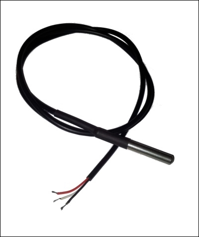
The temperature sensor used in my prototype is the one shown in the following image:
Note
The devices can be purchased at the following link (or by surfing the Internet): http://www.cosino.io/product/waterproof-temperature-sensor.
The datasheet of this device is available at http://datasheets.maximintegrated.com/en/ds/DS18B20.pdf.
As you can see, it's a waterproof device, so we can safely put it into the water to get its temperature.
This device is a 1-Wire device and we can get access to it by using the w1-gpio driver, which emulates a 1-Wire controller by using a standard BeagleBone Black GPIO pin. The electrical connection must be done according to the following table, keeping in mind that the sensor has three colored connection cables:
|
Pin |
Cable color |
|---|---|
|
P9.4 - Vcc |
Red |
|
P8.11 - GPIO1_13 |
White |
|
P9.2 - GND |
Black |
Note
Interested readers can follow this URL for more information about how 1-Wire works: http://en.wikipedia.org/wiki/1-Wire
Keep in mind that, since our 1-Wire controller is implemented in software, we have to add a pull-up resistor of 4.7KΩ between the red and white cable in order to make it work!
Once all connections are in place, we can use the chapter_03/BB-W1-GPIO-00A0.dts file in the book's example code repository to enable the 1-Wire controller on the P8.11 pin of the BeagleBone Black's expansion connector. The following snippet shows the relevant code where we enable the w1-gpio driver and assign to it the proper GPIO:
   fragment@1 {
      target = <&ocp>;

      __overlay__ {
         #address-cells  = <1>;
         #size-cell      = <0>;
         status          = "okay";

         /* Setup the pins */
         pinctrl-names   = "default";
         pinctrl-0       = <&bb_w1_pins>;

         /* Define the new one-wire master as based on w1-gpio
         * and using GPIO1_13
         */
         onewire@0 {
            compatible      = "w1-gpio";
            gpios           = <&gpio2 13 0>;
         };
      };
   };
To enable it, we must use the dtc program to compile it as follows:
root@beaglebone:~# dtc -O dtb -o /lib/firmware/BB-W1-GPIO-00A0.dtbo -b 0 -@ BB-W1-GPIO-00A0.dts
Then, we have to load it into the kernel with the following command:
root@beaglebone:~# echo BB-W1-GPIO > /sys/devices/bone_capemgr.9/slots
If everything works well, we should see a new 1-Wire device under the /sys/bus/w1/devices/ directory, as follows:
root@beaglebone:~# ls /sys/bus/w1/devices/
28-000004b541e9  w1_bus_master1
The new temperature sensor is represented by the directory named 28-000004b541e9. To read the current temperature, we can use the cat command on the w1_slave file as follows:
root@beaglebone:~# cat /sys/bus/w1/devices/28-000004b541e9/w1_slave
d8 01 00 04 1f ff 08 10 1c : crc=1c YES
d8 01 00 04 1f ff 08 10 1c t=29500
In the preceding example, the current temperature is t=29500, which is expressed in millicelsius degree (m°C), so it's equivalent to 29.5°C.
The fish feeder is a device that can release some feed by moving a motor. Its functioning is represented in the following screenshot:
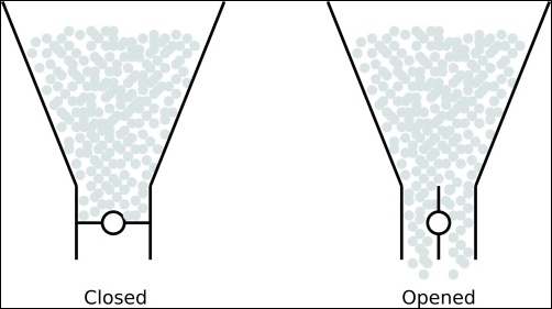
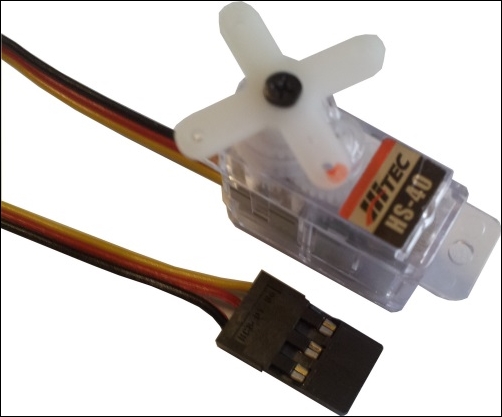
In the closed position, the motor is at horizontal position, so the feed cannot fall down, while in the Open position, the motor is at vertical position, so that the feed can fall down. I have no real fish feeder, but looking at the preceding functioning, we can simulate it by using the servo motor shown in the following screenshot:
Note
The device can be purchased at the following link (or by surfing the Internet): http://www.cosino.io/product/nano-servo-motor.
The datasheet of this device is available at http://hitecrcd.com/files/Servomanual.pdf.
This device can be controlled in position, and it can rotate by 90 degrees with a proper PWM signal in input. In fact, reading into the datasheet, we discover that the servo can be managed by using a periodic square waveform with a period (T) of 20ms and with a high state time (thigh) between 0.9ms and 2.1ms with 1.5ms as (more or less) center. So, we can consider the motor in the Open position when thigh =1ms and in the Close position when thigh=2ms (of course, these values should be carefully calibrated once the feeder is really built up!).
Let's connect the servo as described by the following table:
|
Pin |
Cable color |
|---|---|
|
P9.3 - Vcc |
Red |
|
P9.22 - PWM |
Yellow |
|
P9.1 - GND |
Black |
Tip
Interested readers can find more details about the PWM at https://en.wikipedia.org/wiki/Pulse-width_modulation.
To test the connections, we have to enable one PWM generator of the BeagleBone Black. So, to respect the preceding connections, we need the one which has its output line on pin P9.22 of the expansion connectors. To do it, we can use the following commands:
root@beaglebone:~# echo am33xx_pwm > /sys/devices/bone_capemgr.9/slots
root@beaglebone:~# echo bone_pwm_P9_22 > /sys/devices/bone_capemgr.9/slots
Then, in the /sys/devices/ocp.3 directory, we should find a new entry related to the new enabled PWM device, as follows:
root@beaglebone:~# ls -d /sys/devices/ocp.3/pwm_*
/sys/devices/ocp.3/pwm_test_P9_22.12
Looking at the /sys/devices/ocp.3/pwm_test_P9_22.12 directory, we see the files we can use to manage our new PWM device:
root@beaglebone:~# ls /sys/devices/ocp.3/pwm_test_P9_22.12/
driver	duty   modalias   period   polarity   power   run   subsystem   uevent
As we can deduce from the preceding file names, we have to properly set up the values into the files named as polarity, period, and duty. So, for instance, the center position of the servo can be achieved by using the following commands:
root@beaglebone:~# echo 0 > /sys/devices/ocp.3/pwm_test_P9_22.12/polarity
root@beaglebone:~# echo 20000000 > /sys/devices/ocp.3/pwm_test_P9_22.12/period
root@beaglebone:~# echo 1500000 > /sys/devices/ocp.3/pwm_test_P9_22.12/duty
The polarity is set to 0 to invert it, while the values written in the other files are time values expressed in nanoseconds, set at a period of 20ms and a duty cycle of 1.5ms, as requested by the datasheet (time values are all in nanoseconds.) Now, to move the gear totally clockwise, we can use the following command:
root@beaglebone:~# echo 2100000 > /sys/devices/ocp.3/pwm_test_P9_22.12/duty
On the other hand, the following command is to move it totally anticlockwise:
root@beaglebone:~# echo 900000 > /sys/devices/ocp.3/pwm_test_P9_22.12/duty
So, by using the following command sequence, we can open and then close (with a delay of 1 second) the gate of the feeder:
echo 1000000 > /sys/devices/ocp.3/pwm_test_P9_22.12/duty
sleep 1
echo 2000000 > /sys/devices/ocp.3/pwm_test_P9_22.12/duty
Note that by simply modifying the delay, we can control how much feed should fall down when the feeder is activated.
The water sensor I used is shown in the following screenshot:

Note
The device can be purchased at the following link (or by surfing the Internet): http://www.cosino.io/product/water_sensor.
This is a really simple device that implements what is shown in the following screenshot, where the resistor (R) has been added to limit the current when the water closes the circuit:
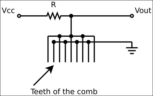
When a single drop of water touches two or more teeth of the comb in the schematic, the circuit is closed and the output voltage (Vout) drops from Vcc to 0V.
So, if we wish to check the water level in our aquarium, that is, if we wish to check for a water leakage, we can imagine to put the aquarium into some sort of saucer, and then this device into it, so, if a water leakage occurs, the water is collected by the saucer, and the output voltage from the sensor should move from Vcc to GND.
The GPIO used for this device are shown in the following table:
|
Pin |
Cable color |
|---|---|
|
P9.3 - 3.3V |
Red |
|
P8.16 - GPIO67 |
Yellow |
|
P9.1 - GND |
Black |
To test the connections, we have to define GPIO 67 as an input line with the following command:
root@beaglebone:~# ../bin/gpio_set.sh 67 in
Then, we can try to read the GPIO status while the sensor is in the water and when it is not, by using the following two commands:
root@beaglebone:~# cat /sys/class/gpio/gpio67/value
0
root@beaglebone:~# cat /sys/class/gpio/gpio67/value
1
The following screenshot shows the prototype I realized to implement this project and to test the software. As you can see, the aquarium has been replaced by a cup of water:
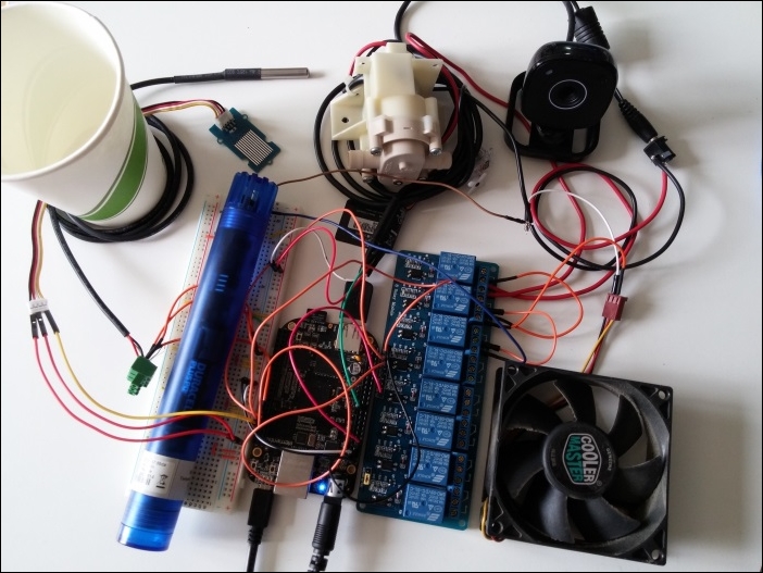
Note that we have two external power suppliers: the usual one at 5V for the BeagleBone Black, and the other one with an output voltage of 12V for the other devices (you can see its connector in the upper-right corner on the right of the webcam.)