
As just stated, in this project we need two different kind of sensors: one to detect when the washing machine starts/stop, and one to detect when someone enters/exits the laundry room. The former task can be achieved by using a sound detector, that is, a device that is able to measure the environment sound level; while the latter task can be achieved by using a light sensor, that is, a device that is able to measure the environment light. Both these signals can be compared with thresholds in order to detect our relevant events.
When the washing machine is running, we should measure a high sound level for a long amount of time; while it is not running, the environment sound should be near to zero for a long time. On the other hand, we can assume that the person designed to pick up the washed clothes has to turn the light on in the laundry room, while the light is normally turned off when there is nobody in the room.
To help the user understand what happens inside the system, we can add two LEDs that can be turned on/off or put in a blinking mode with special meanings (in the next section, I'm going to explain these meanings in detail).
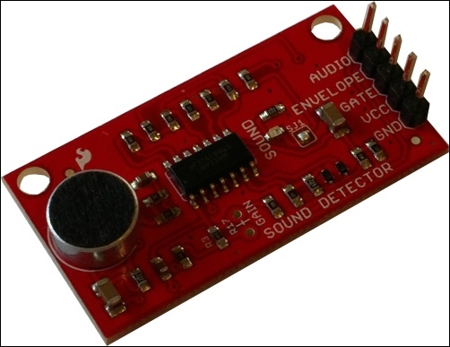
The device to detect the environment sound used in this project is shown in the following image:
Note
The devices can be purchased at the following link (or by surfing the Internet): http://www.cosino.io/product/sound-detector.
The board is based on the amplifier LMV324 with the datasheet available at http://dlnmh9ip6v2uc.cloudfront.net/datasheets/Sensors/Sound/LMV324.pdf, while the board's schematic is available at http://dlnmh9ip6v2uc.cloudfront.net/datasheets/Sensors/Sound/sound-detector.pdf.
This device is very simple since it presents three outputs: the one labeled as AUDIO can be used to directly get the audio captured, while the output labeled ENVELOPE can be used to easily read the amplitude of sound by simply reading the analog voltage. The last output labeled GATE is a binary indication of the presence of the sound by using a fixed threshold (even if you can change it by changing the on-board resistors).
For our prototype, we can use the ENVELOPE output since we can read an analog voltage. Not only this, it allows us to set our own software threshold too. So, let's see the connections in the following table:
|
Pin |
Sound Sensor Pin |
|---|---|
|
P9.4 - Vcc |
VCC |
|
P9.39 - AIN0 |
R @ENVELOPE |
|
P9.3 - GND |
GND |
As already mentioned in Chapter 2, Ultrasonic Parking Assistant, the ADC's input must be limited to 1.8V and since the Vcc level is 3.3V, we can use the voltage divider proposed there in order to scale the output voltage by a factor of 2. Be sure, then, that the maximum input level is not greater than 1.8V. So, the reader should not directly connect the P9.39 pin with the sound detector; they should use the resistors connected as in Chapter 2, Ultrasonic Parking Assistant, to protect the BeagleBone Black's ADC.
Now, to verify that all the connections are okay, we enable the BeagleBone Black's ADCs by using the following command:
root@beaglebone:~# echo cape-bone-iio > /sys/devices/bone_capemgr.9/slots
Then, we can read the captured sound envelope with the following command:
root@beaglebone:~# cat /sys/devices/ocp.3/helper.12/AIN0
24
If we try to speak while we rerun the command, we should get a higher value, as follows:
root@beaglebone:~# cat /sys/devices/ocp.3/helper.12/AIN0
201
So, the higher the environment sound, the higher the returned value.
Tip
Let me remind you again that, as stated in Chapter 1, Dangerous Gas Sensors, the ADC can also be read by using another file's still in the sysfs filesystem with the following command:
root@beaglebone:~# cat /sys/bus/iio/devices/iio:device0/in_voltage0_raw
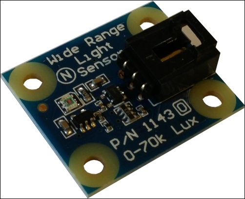
The light sensor is the device shown in the following image:
Note
The devices can be purchased at the following link (or by surfing the Internet): http://www.cosino.io/product/light-sensor.
The user guide of this device is available at http://www.phidgets.com/docs/1143_User_Guide.
As for the sound detector, this device has an analog output that can be used to measure the environment luminosity. According to the user guide, the luminosity can be obtained by using the following formula:
Luminosity(lux) = em*sensor_output+b
Here, sensor_output is the raw value from the sensor, and the m and b are well-defined constants used to get a rough approximation. However, since we are only interested in measuring the light presence and not its precise intensity, we can use our own values or, to make it as simple as possible, the sensor_output value directly.
In the user guide, we also read that even if the device needs a 5V Vcc to function, its output value will not exceed 2.5V. So, considering that our BeagleBone Black's ADC maximum input value is 1.8V, we can use the voltage divider as above to scale down the output value by 2, thus being sure that the 1.8V threshold is satisfied.
The connections are as shown in the following table:
|
Pin |
Light sensor cable |
|---|---|
|
P9.6 - Vcc |
red |
|
P9.40 - AIN1 |
R @white |
|
P9.1 - GND |
black |
Now, as done in the previous section for the sound detector, we can test the device by using the following command:
root@beaglebone:~# cat /sys/devices/ocp.3/helper.12/AIN1
386
However, if I put the device under a light, I get:
root@beaglebone:~# cat /sys/devices/ocp.3/helper.12/AIN1
528
Whereas if I cover the sensor with a cup of coffee, I get:
root@beaglebone:~# cat /sys/devices/ocp.3/helper.12/AIN1
79
So, as for the sound detector, the same rule exists: the higher the environment light intensity, the higher the returned value from the sensor.
To connect the LEDs, we can use the same circuitry that was used in Chapter 1, Dangerous Gas Sensors. The connections are reported in the following table:
|
Pin |
LED color |
|---|---|
|
P8.9 - GPIO69 |
R @red |
|
P8.10 - GPIO68 |
R @yellow |
To test the connections, we can use the following commands to set up the lines as outputs and then to set them into a high state:
root@beaglebone:~# ../bin/gpio_set.sh 68 out
root@beaglebone:~# ../bin/gpio_set.sh 69 out
root@beaglebone:~# echo 1 > /sys/class/gpio/gpio68/value
root@beaglebone:~# echo 1 > /sys/class/gpio/gpio69/value
If everything works well, you should see both LEDs turned on.
The following image shows the prototype I realized to implement this project and to test the software:

Nothing special to say here, apart from the fact that you must provide a network connection for your BeagleBone Black; otherwise, the WhatsApp alerting service will not work! As you can see, I used a normal Ethernet cable, but let me remind that you can also use a USB connection with the host, as mentioned in the Preface.