
As just stated, in this project we're trying to implement two different setups: the first one uses the analog output of the ultrasonic sensor and implements a circuitry, where all the devices are directly connected with the BeagleBone Black (all peripherals are near the board); on the other hand, the second setup allows us to remotely manage the ultrasonic sensor by using an USB connection, so we can mount the sensor far from the BeagleBone Black board.
Simply speaking, we can put the sensor in one place while the LEDs are in a different location, maybe in a more visible position, as shown in the following image:
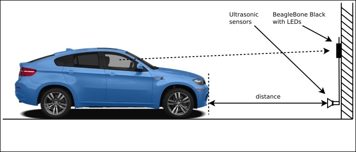
As you can see, the dotted arrow, which represents the driver's point of view, is more clear if the LEDs are in a upper position with respect to the distance sensor that should be located near to the floor to better catch the car frontal.
In this setup, we're going to use an ADC pin of our BeagleBone Black to read the analog output of the ultrasonic sensor.
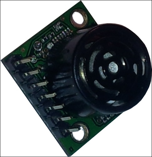
The following image shows the ultrasonic sensor that I used on my prototype:
Note
The devices can be purchased at the following link (or by surfing the Internet):
http://www.cosino.io/product/ultrasonic-distance-sensor.
The datasheet of this device is available at http://www.maxbotix.com/documents/XL-MaxSonar-EZ_Datasheet.pdf.
This device is really interesting due to the fact it has several output channels useful to retrieve the measured distance. In particular, it can give us the measurement via an analog voltage channel and via a serial port; the former communication channel is used in this setup, while the latter will be discussed in the second setup.
Looking into the datasheet, we discover that the analog output has a resolution of Vcc/1024 per cm with a maximum reported range of ~700 mm at 5V and ~600 cm at 3.3V. In this setup, we use Vcc set to 3.3V so the maximum output voltage (VoutMAX) will result as:
- VoutMAX = 3.3V / 1024 * 600 ≈ 1.93V
Remembering that the BeagleBone Black's ADCs have a maximum input voltage of 1.8V, we have to find a way to scale down this value. A quick and dirty trick is to use a classic voltage divider, as shown in the following diagram:

By using the preceding circuit, we simply divide the sensor output by 2. The voltage at ADC in pin is given by the following formula:
- VADCin = R / (R + R) * Vout = R / 2 R * Vout = 1 / 2 * Vout
So, the only thing to do is to choose a suitable value for the two resistors (R). In my prototype, I set this value to R=6.8KΩ, which is a reasonable value to have to acquire a suitable current flooding out from the sensor.
In this situation, our resolution becomes ~1.61mV/cm, and the connections to be done on the BeagleBone Black are shown in the following table:
|
Pin |
Distance sensor pin (label) |
|---|---|
|
P9.1 - GND |
7 |
|
P9.3 - 3.3V |
6 (Vcc) |
|
P9.39 - AIN0 |
3 (AN) |
Now, to enable the BeagleBone Black's ADC lines, we can use the following command as we already did in Chapter 1, Dangerous Gas Sensors:
root@beaglebone:~# echo cape-bone-iio > /sys/devices/bone_capemgr.9/slots
If everything works well, we should get the following kernel messages:
part_number 'cape-bone-iio', version 'N/A'
slot #7: generic override
bone: Using override eeprom data at slot 7
slot #7: 'Override Board Name,00A0,Override Manuf,cape-bone-iio'
slot #7: Requesting part number/version based 'cape-bone-iio-00A0.dtbo
slot #7: Requesting firmware 'cape-bone-iio-00A0.dtbo' for board-name 'Override Board Name', version '00A0'
slot #7: dtbo 'cape-bone-iio-00A0.dtbo' loaded; converting to live tree
slot #7: #1 overlays
bone-iio-helper helper.12: ready
slot #7: Applied #1 overlays.
Then, the AIN0, AIN1, …, AIN7 files should become available, as follows:
root@beaglebone:~# find /sys -name '*AIN*'
/sys/devices/ocp.3/helper.12/AIN0
/sys/devices/ocp.3/helper.12/AIN1
/sys/devices/ocp.3/helper.12/AIN2
/sys/devices/ocp.3/helper.12/AIN3
/sys/devices/ocp.3/helper.12/AIN4
/sys/devices/ocp.3/helper.12/AIN5
/sys/devices/ocp.3/helper.12/AIN6
/sys/devices/ocp.3/helper.12/AIN7
Then, we can read the input data by using the cat command, as follows:
root@beaglebone:~# cat /sys/devices/ocp.3/helper.12/AIN0
1716
Tip
As already stated in Chapter 1, Dangerous Gas Sensors, the ADC can also be read by using another file's still into the sysfs filesystem with the following command:
root@beaglebone:~# cat /sys/bus/iio/devices/iio:device0/in_voltage0_raw
Now, we have to find a way to convert the read values from the ADC into a distance measured in meters so that we can decide how to manage the LEDs to give the feedback to the driver. Recalling what was just said, the resolution is ~1.61mV/cm, and considering that the resolution of the ADC is 12 bits and the maximum voltage is 3.3V, the distance (d) in centimeters between the car and the wall is given by the following formula (where the value n is the data read from the ADC):
- d = 3.3V * n / 4095 / 0.00161V/cm
Note that these are estimated values, so it is better to do a calibration of the sensor in order to have the correct reads at least near the lowest value that we wish to measure (in our example, this value is 0.20 m.) To do this, we can put something at 20 cm from the sensor, measure the output value from the ADC, and then calculate a compensating value K in order that the following formula will return exactly the value 20:
- dcalib = K * 3.3V * n/4095 / 0.00161V/cm
Note that in case of no calibration, K can be set to 1 (In this case, we obtain again the original formula, d = dcalib.)
On my prototype, putting an object at 20 cm from the sensor, I get the following value:
root@beaglebone:~# cat /sys/devices/ocp.3/helper.12/AIN0
29
So, K should be set to 1.38.
The LEDs' connections are very simple since they can be directly connected with the BeagleBone Black's GPIO pins, as shown the following diagram, which shows the schematic of one single LED connection that can be replicated for each LED:
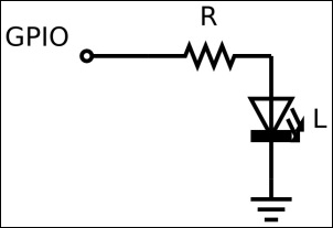
We have 5 LEDs, so we need 5 GPIO lines. We can use the following connections:
|
Pin |
LED color |
Activated when distance is under |
|---|---|---|
|
P8.45-GPIO44 |
White |
5.00 m |
|
P8.46-GPIO67 |
Yellow |
2.00 m |
|
P8.7-GPIO69 |
Red |
1.00 m |
|
P8.8-GPIO68 |
Red |
0.50 m |
|
P8.9-GPIO45 |
Red |
0.20 m |
The white LED is used to signal to the user that they are driving at less than 5 m from the wall; the yellow is used to signal that they are driving at less than 2 m from the wall; and the red LED is used to signal that the garage wall is approaching at less than 1 m, 0.50 m, and 0.20 m.
To test the LEDs' connection, we can use the same commands used in Chapter 1, Dangerous Gas Sensors. For instance, we can test the LED on GPIO68 by using the following commands to set up the GPIO first and then to turn it off and on:
root@beaglebone:~# echo 68 > /sys/class/gpio/export
root@beaglebone:~# echo out > /sys/class/gpio/gpio68/direction
root@beaglebone:~# echo 0 > /sys/class/gpio/gpio68/value
root@beaglebone:~# echo 1 > /sys/class/gpio/gpio68/value
In this setup, we're going to use BeagleBone Black's serial port to read the measured distance from the ultrasonic sensor.
This time, we are interested at the datasheet section where the serial output capability of our sensor is described. In particular, we read:
The Pin 5 output delivers asynchronous serial with an RS232 format, except voltages are 0-Vcc. The output is an ASCII capital "R", followed by three ASCII character digits representing the range in centimeters up to a maximum of 765, followed by a carriage return (ASCII 13). The baud rate is 9600, 8 bits, no parity, with one stop bit. Although the voltage of 0-Vcc is outside the RS232 standard, most RS232 devices have sufficient margin to read 0-Vcc serial data. If standard voltage level RS232 is desired, invert, and connect an RS232 converter.
This is very interesting for two main reasons:
- The measurement is very precise due to the fact that the sensor gives it to us in a digital format and not by using an analog format (so the measurement is more immune to disturbs.)
- The information can be sent over a RS-232 line (even if with some electronic fixes that will be presented soon), which will allow us to have the system core in a different location with respect to the sensor, providing a better usability of the whole system.
So, by using this new setup, the LEDs are still mounted on the BeagleBone Black, while the distance sensor is connected remotely through a RS-232 line. However, we cannot use a classic RS-232 line due to the fact that we still have to supply power to the sensor, and no power can be transferred via a standard RS-232 cable!
The solution is to use a RS-232 connection over a USB cable. In fact, by using a standard USB cable, we are able to send/receive RS-232 data with the needed power supply.
However, some issues are still present:
- The USB power voltage is 5V, so we need a USB-to-serial converter that can manage such voltage level by default, or, is at least 5V tolerant.
- Reading carefully the preceding snippet of the datasheet, we discover that the output level is TLL and inverted! So, before sending the TX signal to the USB-to-serial converter (to the RX pin), we must electrically invert it. (Okay don't panic! I'm going to explain this carefully.)
The solution for the first problem is to use the following USB-to-serial converter, which not only works at 3.3V, but also is 5V tolerant.

Note
The devices can be purchased at the following link (or by surfing the Internet):
http://www.cosino.io/product/usb-to-serial-converter.
The datasheet of this device is available at https://www.silabs.com/Support%20Documents/TechnicalDocs/cp2104.pdf.
In order to address the second problem, we can use the following circuitry to invert the TTL levels of the TX signal of the sensor:

The functioning is quite simple—it's a logical NOT port with a voltage level translator. When a logical 0 (a voltage near 0V) is applied to Vin, the transistor (T) doesn't work, so no current can pass through it and there is no voltage loss on resistor R2 and the Vout is 5V (a logical 1). On the other hand, when a logical 1 (a voltage near 3.3V) is applied to Vin, the transistor (T) is turned on and a current can now flow through it, and the Vout drops down to a voltage near 0V (a logical 0). The following table shows the circuitry functioning in a clear manner, which you can see that it works exactly as we expected!
|
Vin (V)/logical |
Vout (V)/logical |
|---|---|
|
0/0 |
5/1 |
|
3.3/1 |
0/0 |
In this situation, the connections to be done on the BeagleBone Black are quite simple. In fact, we have to connect a normal USB cable to the USB-to-serial converter and then connect it to the distance sensor, as shown in the following table:
|
USB-to-serial Pin |
Distance sensor pin (label) |
|---|---|
|
GND |
7 |
|
VBUS |
6 (Vcc) |
|
RX |
5 (/TX) |
Tip
Note that in the table, I used the /TX electronic notation for the ultrasonic sensor's TX pin (in C, we can write !TX), since, as already stated, its output signal must be inverted, so, in reality, the TX pin of the distance sensor must be connected with the Vin pin of the TTL inverter, while the Vout is the effective signal /TX that must be connected to the USB-to-serial RX pin!
If we decide to use this setup for the distance sensor, the job, from the software point of view, is simpler, since no calibration is needed at all due to the fact that the sensor will return to us the distance in a digital format, that is, without any possible errors due to the analog to digital conversion or voltage scaling, as seen in the preceding section. In fact, we can get the distance simply by reading it from the serial port over the USB connection; so, if everything works well, once we connect the USB cable we should see the following kernel messages:
hub 1-0:1.0: state 7 ports 1 chg 0000 evt 0002
usb 1-1: reset full-speed USB device number 2 using musb-hdrc
hub 1-0:1.0: state 7 ports 1 chg 0000 evt 0002
usb 1-1: cp210x converter now attached to ttyUSB0
The /dev/ttyUSB0 device is now available:
root@beaglebone:~/chapter_02# ls -l /dev/ttyUSB0
crw-rw---T 1 root dialout 188, 0 Apr 23 20:28 /dev/ttyUSB0
Now, to read the measurements, we have to configure the serial port as requested by the datasheet with the following command:
root@beaglebone:~# stty -F /dev/ttyUSB0 9600
Then, the data can be displayed in real-time with the following command:
root@beaglebone:~# cat /dev/ttyUSB0
126
The following screenshot shows the prototype that I realized to implement this project and to test the software.
Note that I implemented both setups: on the left-half of the breadboard, there is the ultrasonic sensor with related circuitry (that is, the part that can be remotized); on the right-half, there are the circuitry for the LEDs; while in the upper center, there is the inverted voltage translator; and in the lower center, there are the two resistors that implement the voltage divider.
Note also the USB-to-serial converter in the center of the screenshot, where I connected the USB cable that is put into the USB host port of the BeagleBone Black:

I also used an external power supplier due to the fact that the external circuitry and the BeagleBone Black may need more power than what the USB port of your PC can supply!