
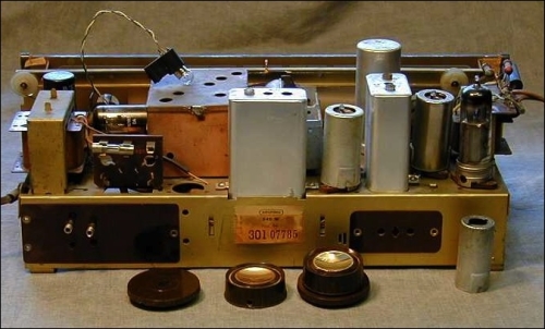
To get some rocking audio going, we thought about wiring a BeagleBone Black up to a personal favorite device of ours: a c. 1960 Gruntal amplifier and radio:
We then thought better of it and decided to go with something a wee bit smaller for our recipe: the TPA2016 PCB, which contains a Texas Instruments chipset and is packaged as a final product by Adafruit:
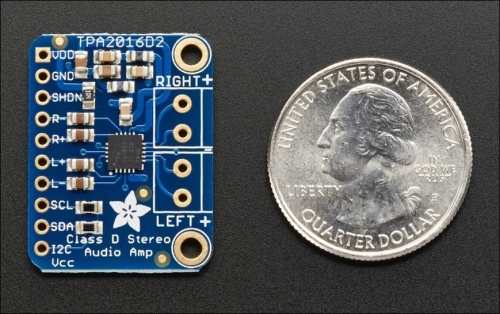
It doesn't pack quite the volume as an ancient tube-based amp, but this surface-mount PCB amp is a heck of a lot handier and easier to use than our antique beauty. Also, it delivers nearly 3W of power for our tunes, plenty of volume for many situations. Additionally, its I2C interface allows us to control audio gain via software instead of using jumpers, switches, or other physical hardware.
In this recipe, you will learn how to set up and test the device on a breadboard with speakers and BeagleBone Black. Afterwards, in a later recipe, we'll use it as part of our kit to set up a listening library on the BBB.
I2C background and usage
I2C (pronounced "eye-squared-C" or "eye-two-see") is a hardware bus intended for motherboards and daughterboards to communicate easily. It is frequently leveraged in embedded applications and typically used in accelerometers, magnetometers, and other sensors, as well as other add-ons requiring low voltage. In our case, we will use it to run a very small audio amplifier.
Other than its power leads, the bus only uses two wires to communicate: SCL and SDA. The first one is the clock line, SCL, which is used to sync any data passing over the bus. The second line, SDA, carries the actual data. I2C also utilizes a simple master/slave relationship between devices, with the bus allowing the roles to be interchangeable. I2C is also good at noise filtering, which is a relevant feature for our recipe.
Working with I2C pins on the BBB is pretty straightforward. There are three I2C buses implemented on the BBB, but only one of these is easy to use:
- I2C0: This is used for some onboard components, such as HDMI, EEPROM, and power management. If we disable it, it will interfere with these components, so it is typically not used unless needed.
- I2C1: This is available for use but requires enabling.
- I2C2: This is usable out of the box (Expansion port P9; refer to table 11 in the SRM). These are the pins that we will use.
Note
I2S bus
I2C should not be confused with Integrated Interchip Sound (I2S), another serial bus available on the BBB. Unlike I2C, which is bidirectional, I2S only handles data in one direction. Coincidentally, I2S is typically used as an interface to communicate PCM audio data between devices, commonly with a Digital to Analog Converter (DAC) audio device, though we will not use it in our audio recipes. There are several helpful tutorials on making a DAC, interface with I2S and connecting it to the BBB, such as the one at http://bit.ly/1HQMc1N.
Here are the materials we need:
- PCB amp kit: This can be TPA2016 or similar. Adafruit has several choices, which you can access at https://www.adafruit.com/search?q=amplifier.
- Speakers: You can use any set of speakers that take mono or stereo mini connector cables.
- Audio input jack: Either one of the following two methods will work:
- 3.5mm Stereo Headphone Jack (breadboard-ready): This is very cheap and available at Sparkfun (https://www.sparkfun.com/products/8032) or Adafruit (https://www.adafruit.com/product/1699) for around USD $1.00.
- 3.5mm stereo plug to "pigtail" cable: This is basically a simple stereo mini cable using a standard plug on one end and a left and right speaker with wire-stripped "tinned" leads on the other. The leads break out, so you can plug them into a breadboard easily. It is cheap and available at Adafruit (https://www.adafruit.com/product/1700) for USD $1.95.
- Mp3 or portable music player: This can be an iPod or smartphone with 3.5mm audio jack output and containing sample music or audio files.
- 2-plug (male) audio cable: A standard 3.5mm cable that you likely already have around the house.
- Soldering iron
- Lead-free solder
- Mini Philips head screwdriver
- Jumper wires
- Breadboard
To prep the PCB amp, we followed some of the guidance provided by Adafruit's tutorial to work with their board (https://learn.adafruit.com/adafruit-tpa2016-2-8w-agc-stereo-audio-amplifier). Perform the following steps:
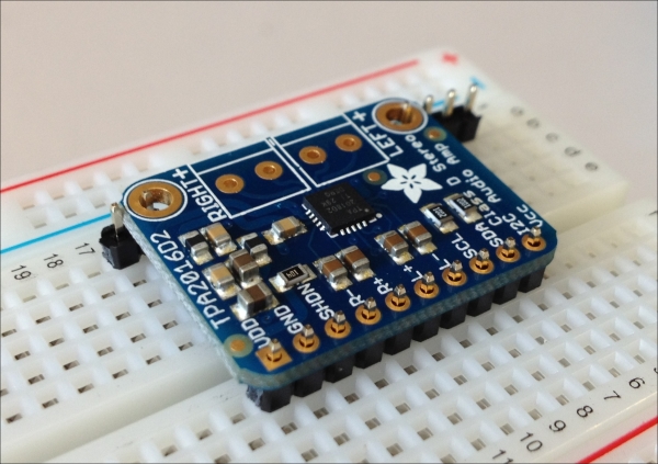
- Your tasks begin with soldering an 8-pin header strip to the 8-holed side of the PCB amp and then soldering the speaker terminal blocks into the marked slots along the opposite side of the board. This is shown for you in the following image:
Note
This recipe is not a general how-to on soldering. If you have never soldered a wire or joint on a PCB, consult the following excellent tutorials:
How to Solder—Through-hole Soldering: https://learn.sparkfun.com/tutorials/how-to-solder---through-hole-soldering/
NYU's ITP soldering lesson: https://itp.nyu.edu/physcomp/Labs/Soldering
Adafruit's excellent guide to soldering: https://learn.adafruit.com/adafruit-guide-excellent-soldering
Instructable secrets of good soldering: http://www.instructables.com/id/How-to-solder-the-secrets-of-good-soldering/
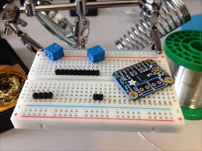
After this, you can begin by inserting the long pins of a header strip with 8 pins into the breadboard, short pins sticking up, as shown in the following picture:
As it is important to get your PCB amp mounted on an even plane, the easiest way to do this is by using the leftover pins to support the board on the opposite edge. To clarify, these pins will not be soldered; they are only there for temporary support.

You then need to solder up the headers on the PCB amp, as you can see on the left-hand side in this picture. We used lead-free solder; so, when finished, the joints will look dull instead of the typically shiny cast from a well-poured leaded joint.
- Solder the speaker terminal blocks to the PCB amp. Verify that your connections are solid. You may notice that the blocks don't sit neatly parallel to one another. This appears to be due to a slight design imperfection in the PCB amp, but there's nothing to worry about functionally.

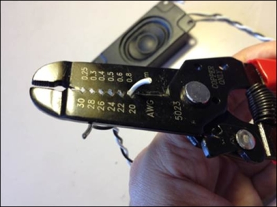
- Snip off the white connector that comes already attached to the ends of the speaker wires:

Following this, with a wire stripper, cut away the wire ends, as you can see in the following image:
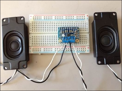
- Next, attach the finished PCB amp to a breadboard. Then, insert the speaker wires into the speaker terminal blocks. The black wires go into the (-) ground connectors, and the white wires into the (+) power connectors. Use a small Philips head screwdriver to first release tension in the block. Finish by tightening it after the wires are inserted. The end result is shown in this image:
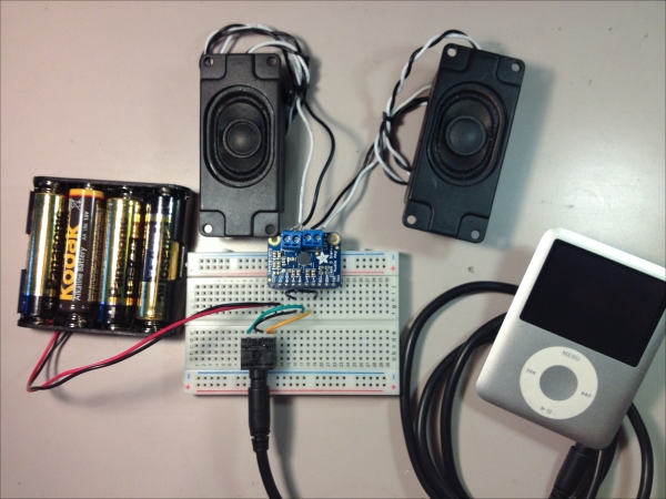
- Since we plan to use sound in this recipe—which is what an audio amplifier is good for—we need to also add some means for sound input. You can use either the breadboard-ready headphone jack, which you will see in the next picture, or the pigtail cable, as described at the beginning of this recipe.
- Hook up your audio player to the other end of the audio cable. In our case, we used an old iPod that we had in a drawer. If you refer closely to the following image, it shows how all the parts should fit together before you have hooked it up to your BBB:
- Choose an audio track on your player and press Play. Now that we know we have solid audio output with all hardware soldered, snipped, breadboarded, and wired properly, we will run an audio test using Python.
- Now, we want to wire the amp up to our BeagleBone Black, following the Fritzing diagram. Although it looks like a thicket of mini jumper wires, the scheme is really simple. In fact, you will notice that on the BBB's GPIO pins, there are only two pins in use other than power and ground.
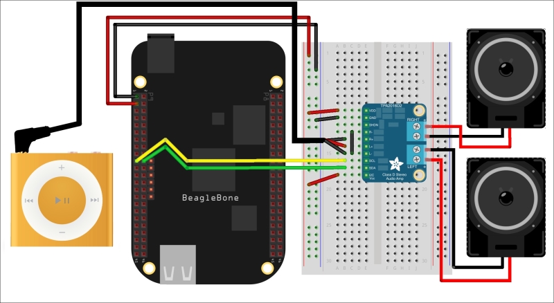
In case there is any uncertainty from the diagram, here is a table clarifying how to wire it up:
FUNCTION
BeagleBone Black
TPA2016 amplifier
Breadboard component
Power
P9_5 (5V) or P9_3 (3.3V)—5V for full capacity of the amp
VDD
Ground
P9_1
GND
I2C
P9_19 (SCL)
SCL
I2C
P9_20 (SDA)
SDA
Audio input—left speaker
L+
L+ on 3.5mm headphone jack
Audio input—right speaker
R+
R+ on 3.5mm headphone jack
Audio ground
L- to R-
Audio ground
R-
R- on 3.5mm headphone jack
- Let's get programming! To start, open up the BoneScript IDE and create a new
.pyfile calledaudio-amp-test1.py. - Download the Python script from our Github repo with following command:
$ git clone https://github.com/HudsonWerks/audio-amplifier.git - Browser to the audio-amplifier directory created and open up the python script in a
nanowindow:$ $ cd audio-amplifier $ sudo nano audio-amp-test1.py
- Now, copy and paste the code into the Cloud9 IDE window.
- Restart a music track on your media player that, in our case, is an iPod. You should be able to hear the track playing through the speakers.
- Now, click on the Run button on the Cloud9 IDE to test the script. Audio levels should shift up and down as you input the (+) or (-) sign at the command prompt.
Success (we hope)! Give yourself a high-five for getting dirtier with your board and adding some PCB add-ons to the mix.