
The first step to make the platform mobile is adding a motor controller. This allows us to control the speed of each wheel (or track) independently. Before you get started, let's spend some time understanding the basics of motor control. The unit moves by engaging the motors. If the desired direction is straight, the motors are run at the same speed. If you want to turn the unit, the motors are run at different speeds. The unit can turn in a circle if you run one motor forward and one backwards.
DC motors are fairly straightforward devices. The speed and direction of this motor are controlled by the magnitude and polarity of the voltage applied to its terminals. The higher the voltage, the faster the motor will turn. If you reverse the polarity of the voltage, you can reverse the direction in which the motor is turning.
The magnitude and polarity of the voltage are not the only important factors when you think about controlling the motors. The power that your motor can apply to move your platform is also determined by the voltage and the current supplied at its terminals.
There are GPIO pins on the BeagleBone Black. If you'd like to learn more about the specific capabilities of these pins, go to http://beagleboard.org/Support/bone101. In this project, you'll use them to create the control voltage and drive your motors. These pins provide direct access to some of the control lines available from the processor itself. However, the unit cannot source enough current, and your motors might not be able to generate enough power to move your mobile platform. You might also cause physical damage to your BeagleBone Black board. That is why you need to use the motor controller, as it will provide both voltage and current so that your platform can move reliably. In this case, I have chosen to hook up the motor controller via USB, making the connections and programming much simpler.
There are numerous possibilities for the motor controller. However, I'm going to suggest one that requires no internal programming and allows you to talk over USB to control the motors. You'll want one that can also control the two motors. The one I prefer is the Pololu TReX Jr Dual Motor Controller DMC02 from Pololu, orderable from www.pololu.com at http://www.pololu.com/product/767. Here is an image:
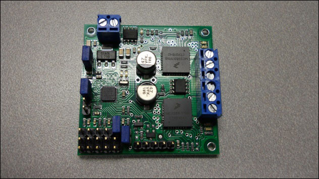
This piece of hardware will convert the USB commands to voltage that controls your motors.
The first step in making your project mobile is connecting the motor controller to the platform. There are three connections you need to make:
- First, you need to connect a battery to the controller
- Second, you need to connect the motor controller to the motors themselves
- Third, you need to connect the motor controller to the BeagleBone Black
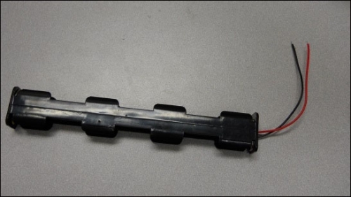
There are a couple of choices with respect to batteries. One choice is to use the battery holder that came with the platform. It should look like this:
Another choice is to use a Li Po Poly RC battery; these carry a much longer charge. If you are going to do this, choose a 2S version, which is 2 cells in series. Here is an image of an RC battery, with connectors to make it easy to disconnect and charge:

You'll also need a battery to power the BeagleBone Black. One easy choice is a cell phone battery that has a USB output. Here is an image of one such device:

This battery will provide more than enough power for your BeagleBone Black. If you chose one with two USB outputs, you'll be able to power a powered USB hub as well, which you will use later in this and in other projects.
Once you've chosen your battery, you'll need to connect the motor controller to the battery and motor. Follow these steps:
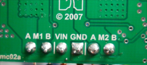
- On the back of the motor controller, notice the labels VIN, A M1 B, A M2 B, and GND:
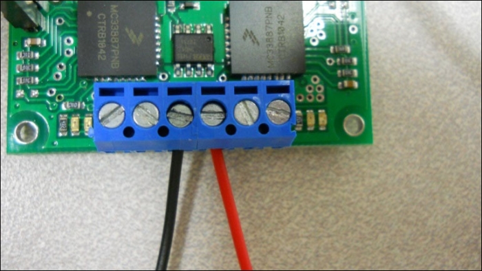
- Once you have the battery pack ready, insert the wires into the motor controller in the blue connectors marked VIN and GND. VIN is the constant DC voltage in from your batteries, and GND is the ground connection from your batteries. A and B are the control signals to your DC motors. You'll notice that on the battery connector, one of the wires is red. Insert it into the VIN connector, and then tighten the screw connector. On the battery connector, you'll notice that the other wire is black. Insert that wire into the connector marked GND and tighten the screw connector. The connections will look like this:
- Now connect one of the motors to the motor controller by connecting the red and black wires with male connectors to the two outer blue screw connectors, the red one to A and the black one to B using the male to male jumper wires. The connection to the motor controller should look like this:

After performing all the preceding steps, the connections to the motor should now look like this:

Now your controller is connected to the battery and motor. The next step is to make sure that the controller works, by connecting it to a remote computer.
Here I would insert a complete layout to connect/power the boards:
- USB hub
- BeagleBoard
- Might be the battery for BeagleBoard
You can now connect the DC motor controller to the USB cable. Here are the steps:
- The motor controller is going to need a serial input, but you'll find it easiest to talk over USB. The USB-to-TTL serial cable is available at amazon.com and a number of other suppliers. Here is an image:

- To do so, connect the TTL end of the cable to the serial connector on the board. On the underside of the board, you will see the following labels:
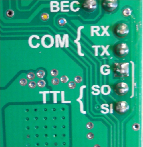
- Now connect the green cable to the SI connection, the white cable to the SO connection, and the black cable to the G connection. Here is an image of what it should look like:

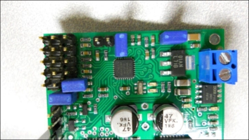
- Now, there's one more step before you connect the board to the BeagleBone Black. Remove the jumper at the top of the board so that the board will accept serial commands. Here's an image of the jumper, and I like to just turn it sideways so that I don't lose the jumper:
You should supply the unit with power by making sure you have batteries in the battery holder. Now that you have your basic motor controller functionality up and running, you need to connect the motor controller to the BeagleBone Black. Plug the USB cable that you just connected to the motor controller to the BeagleBone Black.
Here is an image of all the pieces of hardware that you have connected:

You might want to configure all of the hardware on top of the mobile platform like this:

Your platform is now assembled The next step will be to control this movement using the BeagleBone Black.