Project 15 – Simple Motor Control
First, you're going to simply control the speed of a DC motor in one direction, using a power transistor, diode, external power supply (to power the motor), and a potentiometer (to control the speed). Any suitable NPN power transistor designed for high current loads can replace the TIP120 transistor.
The external power supply can be a set of batteries or a “wall wart” style external DC power supply. The power source must have enough voltage and current to drive the motor. The voltage must not exceed that required by the motor. For my testing purposes, I used a DC power supply that provided 5v at 500mA, which was enough for the 5v DC motor I was using. Note that if you use a power supply with voltage higher than the motor can handle, you may damage it permanently.
Parts Required
| DC Motor | 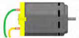 |
| 10kΩ Potentiometer | 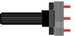 |
| TIP120 Transistor* | 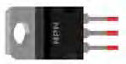 |
| 1N4001 Diode* | |
| Jack Plug |  |
| External Power Supply | 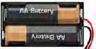 |
Connect It Up
First, make sure your Arduino is powered off by unplugging it from the USB cable. Now, take the required parts and connect them as shown in Figure 5-1. It is essential that you check and double check that all of your connections are as they should be before supplying power to the circuit. Failure to do so may result in damage to the components or the Arduino. The diode plays an essential role in protecting the Arduino from back EMF, which I will explain later.
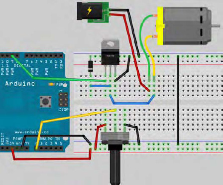
Figure 5-1. The circuit for Project 15 – Simple Motor Control (see insert for color version)
Enter The Code
Open up your Arduino IDE and type in the code from Listing 5-1. Before uploading your code, disconnect the external power supply to the motor and ensure the potentiometer is turned clockwise all the way. Now upload the code to the Arduino.
Listing 5-1. Code for Project 15
// Project 15 - Simple Motor Control


int potPin = 0;           // Analog in 0 connected to the potentiometer
int transistorPin = 9;     // PWM Pin 9 connected to the base of the transistor

int potValue = 0;         // value returned from the potentiometer


void setup() {

  // set  the transistor pin as output:

  pinMode(transistorPin, OUTPUT);

}


void loop() {

  // read the potentiometer, convert it to 0 - 255:

  potValue = analogRead(potPin) / 4;

  // use that to control the transistor:

  analogWrite(transistorPin, potValue);

}
Once the code is uploaded, connect the external power supply. You can now turn the potentiometer to control the speed of the motor.
Project 15 – Simple Motor Control – Code Overview
First, declare the three variables that will hold the value for the Analog Pin connected to the potentiometer, the PWM pin connected to the base of the transistor, and one to hold the value read back from the potentiometer from Analog Pin 0:
int potPin = 0;           // Analog in 0 connected to the potentiometer

int transistorPin = 9     // PWM Pin 9 connected to the base of the transistor

int potValue = 0;         // value returned from the potentiometer
In the setup() function, you set the pinmode of the transistor pin to output:
void setup() {

  // set  the transistor pin as output:

  pinMode(transistorPin, OUTPUT);

}
In the main loop, potValue is set to the value read in from Analog Pin 0 (the potPin) and then divided by 4:
potValue = analogRead(potPin) / 4;
You need to divide the value read in by 4 as the analog value will range from 0 for 0 volts to 1023 for 5 volts. The value you need to write out to the transistor pin can only range from 0 to 255, so you divide the value of analog pin 0 (max 1023) by 4 to give the maximum value of 255 for setting the Digital Pin 9 (using analogWrite, as you are using PWM).
The code then writes out to the transistor pin the value of the pot:
analogWrite(transistorPin, potValue);
In other words, when you rotate the potentiometer, different values ranging from 0 to 1023 are read in; these are converted to the range 0 to 255. Then that value is written out (via PWM) to Digital Pin 11, which changes the speed of the DC motor. Turn the pot all the way to the right and the motor goes off, turn it to the left and it speeds up until it reaches maximum speed. The code is very simple and you have learned nothing new.
Let's now take a look at the hardware used in this project and see how it all works.
Project 15 – Simple Motor Control – Hardware Overview
The circuit is essentially split into two sections. Section 1 is the potentiometer, which is connected to 5v and Ground with the centre pin going into Analog Pin 0. As the potentiometer is rotated, the resistance changes to allow voltages from 0 to 5v to come out of the centre pin, where the value is read using Analog Pin 0.
The second section is what controls the power to the motor. The digital pins on the Arduino give out a maximum of 40mA (milliamps). A DC Motor may require around 500mA to operate at full speed; this is obviously too much for the Arduino. If you were to try to drive the motor directly from a pin on the Arduino, serious and permanent damage could occur.
Therefore, you need to find a way to supply it with a higher current. The answer is to take power from an external power supply, which will supply enough current to power the motor. You could use the 5v output from the Arduino, which can provide up to 800mA when connected to an eternal power supply. However, Arduino boards are expensive and it is all too easy to damage them when connecting them up to high current sources such as DC motors. So play it safe and use an external power supply. Also, your motor may require 9v or 12v or higher amperages and this is beyond anything the Arduino can supply.
Note also that this project controls the speed of the motor, so you need a way to control that voltage to speed up or slow down the motor. This is where the TIP-120 transistor comes in.
Transistors
A transistor is essentially a digital switch. It can also be used as a power amplifier. In your circuit, you'll use it as a switch. The electronic symbol for a transistor looks like Figure 5-2.
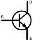
Figure 5-2. The symbol for an NPN transistor
The transistor has 3 legs: the Base, the Collector, and the Emitter. These are marked as C, B and E on the diagram. In your circuit, you have up to 5 volts going into the Base via Digital Pin 9. The Collector is connected to one terminal on the motor. The Emitter is connected to Ground. Whenever you apply a voltage to the Base via Digital Pin 9, the transistor turns on, allowing current to flow through it between the Emitter and Collector and thus powering the motor that is connected in series with this circuit. By applying a small current at the Base, you can control a larger current between Emitter and Collector.
Transistors are the key components in just about any piece of modern electronic equipment. Many people consider transistors to be the greatest invention of the twentieth century. Desktop PC and laptop processors have between 300 million and 1 billion transistors.
In your case, you have used the transistor as a switch to turn on and off a higher voltage and current. When a current is applied at the base, the voltage applied at the Collector is turned on and allowed to flow between the Collector and Emitter. As you are pulsing your signal, the transistor is turned on and off many times per second; it is this pulsed current that controls the speed of the motor.
Motors
A motor is an electromagnet, and it has a magnetic field while power is supplied to it. When the power is removed, the magnetic field collapses; this collapsing field can produce a reverse voltage that goes back up its wiring. This could seriously damage your Arduino, and this is why the diode has been placed the wrong way around on the circuit. The white stripe on the diode normally goes to ground. Power will flow from the positive side to the negative side. As you have it the wrong way around, no power will flow down it at all. However, if the motor were to produce a “back EMF” (electromotive force) and send current back down the wire, the diode would act as a valve to prevent it from doing so. The diode in your circuit is therefore put in place to protect your Arduino.
If you were to connect a DC motor directly to a multimeter with no other components connected to it and then spin the shaft of the motor, you would see that the motor generates a current. This is exactly how wind turbines work. When you have the motor powered up and spinning and you then remove the power, the motor will keep on spinning under its own inertia until it comes to a stop. In that short time while the motor is spinning without power applied, it is generating a current. This is the aforementioned “back EMF.” Again, the diode acts as a valve and ensures that the electricity does not flow back to the circuit and damage other components.
Diodes
Diodes are one-way valves. In exactly the same way that a non-return valve in a water pipe will allow water to flow in one direction but not in the other, the diode allows a current to flow in one direction but not the other. You came across diodes when you used LEDs. An LED has a polarity. You connect the positive terminal of the power to the long lead on the LED to make the LED turn on. By turning the LED around, the LED will not only fail to illuminate but will also prevent electricity from flowing across its terminals. The diode has a white band around it next to the negative lead. Imagine the white band as being a barrier. Electricity flows through the diode from the terminal that has no barrier. When you reverse the voltage and try to make it flow through the side that has the white band, the current will be stopped.
Diodes are essential in protecting circuits from a reverse voltage, such as if you connecting a power supply the wrong way around or if a voltage is reversed such as the back EMF in your circuit. Therefore, always try to use them in your circuits wherever there is a danger of the power being reversed either by user error or via phenomena such as back EMF.