
CHAPTER 6
NETWORK TOPOLOGIES, PROTOCOLS, AND DESIGN
Gary C. Kessler and N. Todd Pritsky
6.1.3 LAN Technology Parameters
6.2.5 Physical versus Logical Topology
6.5 LAN PROTOCOLS AND STANDARDS
6.5.1 OSI Model versus LAN Model Architectures
6.5.3 IEEE 802.3 CSMA/CD Standard
6.5.5 IEEE 802.5 Token-Ring Standard
This chapter provides a broad overview of local area network (LAN) concepts, basic terms, standards, and technologies. These topics are important to give the information security professional a better understanding of the terms that might be used to describe a particular network implementation and its products. The chapter also is written with an eye to what information security professionals need to know; for a more complete overview of the topic, the reader is referred to general LAN texts, such as those listed in Section 6.10.
6.1 OVERVIEW.
There are a number of ways to describe a LAN, and each will provide a glimpse as to implementation and product differences as well as points of security exposures. This section introduces various terms and perspectives as a basis for the discussion in the following sections.
6.1.1 LAN Characteristics.
One way of describing LANs is to describe the characteristics that distinguish a local network from other types of networks. The most common characteristics are:
- Small geographic scope (the two most distant stations may be up to 5 kilometers [km] or so apart)
- Fast speed (data rates well in excess of 1 Mbps], up to 1 Gbps])
- Special media (common use of coaxial cable and optical fiber, as well as twisted pair)
- Private ownership
This type of network, then, has a very different look and feel than the Internet or some other public or private wide area networks (WAN). More people have access to the LAN infrastructure than to the infrastructure of just about any WAN. LAN users can easily “spy” on each other by sniffing packets, something that is generally very difficult on the Internet. A single user can bring the LAN to a standstill.
The corporate LAN is generally the users' primary access to the Internet. The users on the LAN are behind the corporate firewall and router; some studies suggest that they are responsible for 80 percent of security incidents.
Often these attacks are due to users' lack of education and awareness, such as choosing poor passwords, not maintaining up-to-date virus signature files, or leaving modems attached to computers on the LAN. Sometimes the attacks are deliberate, such as using a packet sniffer to learn another user's password or taking steps to degrade network performance.
6.1.2 LAN Components.
In general, there are four basic components required to build a LAN, providing their own vulnerabilities and exposures from a security perspective:
- Computers. These are the basic devices that are connected on the network. Read “computer” very broadly; the term can include personal computers (PCs), minicomputers, mainframes, file servers, printers, plotters, communications servers, and network interconnection devices. It can also include protocol analyzers.
- Media. These are the physical means by which the computers are interconnected. LAN media include unshielded twisted pair (UTP), coaxial cable (coax), optical fiber, and wireless devices. The wireline media have connection points throughout an area where devices can attach to the network, and everyplace is a potential connection point in a wireless environment.
- Network interface card (NIC). This is the physical attachment from the computer to the LAN medium. Most NICs are internal cards, and all that actually is seen is the physical attachment to the LAN, often an RJ-45 jack. NICs range widely in price depending on their capabilities, intended use, and vendor; a no-name, 10 Mbps Ethernet NIC for a desktop personal computer (PC) can be had for less than $10; a 3Com 10/100 Mbps PC Card NIC for a laptop can cost over $150.
- 4. Software. The three components above provide physical connectivity. Software—often called a network operating system (NOS)—is necessary for the devices to actually take advantage of the resource sharing that the LAN can provide. The NOS can support many types of services such as file sharing, print sharing, client/server operation, communications services, and more.
While the LAN needs to be examined in a holistic fashion, each of these components at each attached node also may require examination.
6.1.3 LAN Technology Parameters.
One final way of discussing the specific operation of the LAN is to describe the technology:
- Physical topology. The physical layout of the medium.
- Logical topology. The logical relationship of the LAN nodes to each other.
- Medium Access Control (MAC) Standard. The specification describing the rules that each node follows to determine when it is its turn to transmit on the medium.
- Use of the Logical Link Control (LLC) protocol. Defines the frame format employed above the MAC layer, and additional services.
- Use of higher-layer protocols. Defines the node-to-node communicating protocols and additional higher-layer applications.
6.1.4 Summary.
It does not matter how a LAN is classified or described. It is essential, however, that the LAN be understood from a variety of perspectives to be able to apply a network security examination.
6.2 LAN TOPOLOGY.
Wide area networks typically use some sort of switched technology, such as traditional circuit switching, packet switching (e.g., X.25), or fast packet switching (e.g., frame relay, asynchronous transfer mode [ATM]). Indeed, the network switches are typically connected by point-to-point lines so that there is a single data transmission on the line at one time.
Historically, LANs have been broadcast networks, meaning that every LAN station hears every transmission on the medium. LAN topologies, then, have to support the broadcast nature of the network and provide full connectivity between all stations.
The topology of a network is used to describe two issues. The physical topology describes how the LAN stations are physically connected so that they can communicate with each other. The logical topology describes how the broadcast nature of the LAN is actually effected, and, therefore, how stations participate in the process of obtaining permission to transmit on the medium. There are three common topologies found in LANs: star, ring, and bus.
6.2.1 Network Control.
Since LANs are broadcast networks, it is imperative that only a single node be allowed to transmit at any one time. All LANs use a distributed access control scheme, meaning that all nodes follow the same rules to access the network medium and no one LAN node controls the other nodes' access. In this way, LAN nodes can come online and off-line without bringing the network down.

EXHIBIT 6.1 Star Topology
This is not meant to suggest that there are no critical elements in a LAN. Indeed, if a central hub, switch, or transmitter fails, the LAN will crash. Distributed control does suggest, however, that all nodes (user stations) follow the same access rules, and failure of a single node will not bring the LAN down. The access control scheme is defined by the MAC protocol.
6.2.2 Star Topology.
In a star topology (see Exhibit 6.1), all devices on the LAN are interconnected through some central device. Since LANs use distributed access control schemes, all communication is from one node to another, and the central device merely provides a pathway between pairs of devices.
Physical star topologies have a tremendous advantage over other topologies in that they greatly ease network administration, maintenance, reconfiguration, and error recovery. Disadvantages include the potential single point of failure.
6.2.3 Ring Topology.
In a ring topology, the nodes are connected by a set of point-to-point links that are organized in a circularly closed fashion (see Exhibit 6.2). Stations connect to the medium using active taps that are actually bit repeaters; a bit is read from the input line, held for a single bit time, then transmitted out to the output line.
A station transmits a message on the network by sending out a bit stream on its outgoing link; thus, rings are unidirectional in nature. Since all of the other stations see the bits one at a time, the intended receiver has no prior warning about an incoming message. For this reason, the transmitter is responsible for removing the message from the ring when the bits come back around. The MAC scheme ensures that multiple stations do not transmit at the same time.

EXHIBIT 6.2 Ring Topology
In addition, a ring is a serial broadcast network. Because a station sends a message one bit at a time, every other station will see the message as it passes through but each will be receiving a different part of the message at any point in time.
Rings are a common physical LAN topology, although, like stars, they have the potential of a single point of failure; if one link or one active tap fails, the integrity of the ring is destroyed. This problem is of such a critical nature that nearly all ring products use a star-wiring scheme or have some sort of redundancy built in for just this eventuality.
6.2.4 Bus Topology.
In a bus topology (see Exhibit 6.3), all devices are connected to a single electrically continuous medium; for this reason, this topology is also called a common cable or shared medium network. Nodes attach to the medium using a passive tap, one that monitors the bit flow without altering it. This is similar to the operation of a voltmeter; it measures the voltage on a power line without changing the available voltage.
Bus networks are analogous to the way appliances are connected to an AC power line. All of the devices draw power from the same source, even if they are on different physical segments of the power distribution network within the building. In addition, the operation of the devices is independent of each other; if the coffeepot breaks, the toaster will still work.
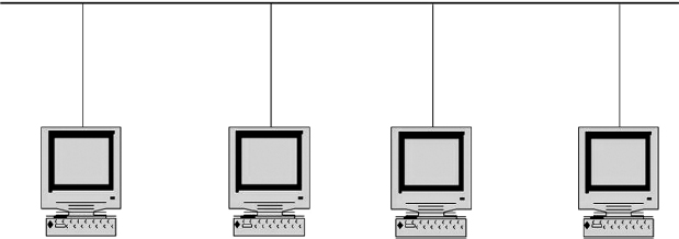
EXHIBIT 6.3 Bus Topology
A bus is a simultaneous broadcast network, meaning that all stations receive a transmitted message at essentially the same time (ignoring propagation delay through the medium). Most home and business LANs employ a baseband bus where DC signals are applied directly to the bus by the transmitter without any modification. In addition, transmissions on a baseband bus are broadcast bidirectionally and cannot be altered by the receivers. Bus LAN technologies are employed on cable television systems. For example, they employ a broadband bus where the signals are modulated (i.e., frequency shifted) to certain frequencies for transmission in one direction or another.
Buses are the oldest LAN topology and are generally limited in the type of medium that they can use. They do not usually suffer from single-point-of-failure problems.
6.2.5 Physical versus Logical Topology.
A distinction was made above between the physical and logical topology of a LAN. As suggested above, physical topology describes how the stations are physically positioned and attached to each other while the logical topology describes how the signals propagate and the logical operation of the network.
In all of today's commonly-used LANs, the logical topology differs from the physical topology. The most common LAN configuration today is a star-wired bus (see Exhibit 6.4). This type of network has a star topology where all stations are physically attached with point-to-point links to a central device. This central device contains a bus that interconnects all of the I/O ports in such a way that when one station transmits a message, all stations will receive it. Since this acts exactly like a simultaneous broadcast, or bus, network, we categorize this configuration as a physical star, logical bus.
Another common configuration is a star-wired ring (see Exhibit 6.5). In this configuration, the bits will travel in logical order from station A to B, C, A, and so forth, which matches the serial broadcast operation of a ring. We call this a physical star, logical ring.
Although uncommon today, another hybrid technology is the bus-wired ring (see Exhibit 6.6). In this configuration, nodes are passively attached to a single cable, forming a physical bus. Each station maintains a table specifying the address of predecessor and successor stations, thus forming a logical ring.
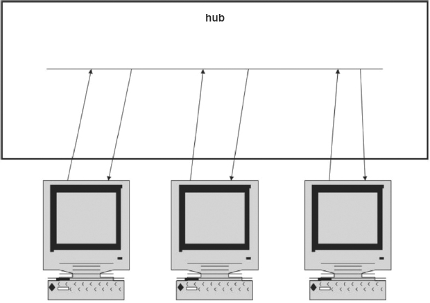
EXHIBIT 6.4 Star-Wired Bus

EXHIBIT 6.5 Star-Wired Ring
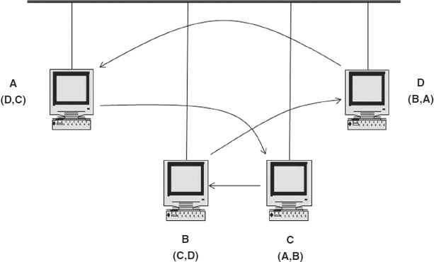
EXHIBIT 6.6 Bus-Wired Ring (The station identifier is shown above the station ID of the predecessor and successor stations in the logical ring.)
6.3 MEDIA.
The next paragraphs discuss the three primary types of LAN media that are currently being used. Due to their relatively high speed, small geographic size, and protected environments, a number of media types can be employed with LANs.
6.3.1 Coaxial Cable.
Coaxial cable (coax) is the original LAN medium. It gets its name from the physical composition of the cable itself (see Exhibit 6.7). At the center of the cable is a conductor, usually made of copper that is surrounded by an insulator, which, in turn, is surrounded by another conductor that acts as an electrical shield. Since the shield completely surrounds the central conductor and the two have a common axis, the shield prevents external electrical noise from affecting signals on the conductor and prevents signals on the conductor from generating noise that affects other cables.
Coaxial cables vary in size from ![]() inch to 1 inch, depending on the thickness of the conductor, shield, and insulation. Applications for coax range from cable television to LANs. Speeds in excess of several hundred Mbps at distances of several hundred to several thousand meters can be achieved. Coaxial cable also has a high immunity from electromagnetic and radio frequency interference.
inch to 1 inch, depending on the thickness of the conductor, shield, and insulation. Applications for coax range from cable television to LANs. Speeds in excess of several hundred Mbps at distances of several hundred to several thousand meters can be achieved. Coaxial cable also has a high immunity from electromagnetic and radio frequency interference.

EXHIBIT 6.7 Coaxial Cable

EXHIBIT 6.8 Unshielded Twisted Pair
Coaxial cable is only seen in physical bus LANs such as Ethernet. The original Ethernet specification, in fact, called for a thin coaxial cable; a later version that employed thin (CATV) coax was dubbed CheaperNet. Coax is not typically found in star or ring networks.
6.3.2 Twisted Pair.
The medium enjoying the largest popularity for LAN applications today is twisted pair. Twisted pair cable consists of two insulated copper conductors that are twisted around each other (see Exhibit 6.8). This is typically 22- to 26-gauge wire, the same that is used for telephone wiring. Twisting the conductors around each other minimizes the effect of external electrical radiation on the signal carried on the wire; if external voltage is applied to one wire of the pair, it will be applied equally to the other wire. The twisting, then, effectively eliminates the effect of the external noise. As the number of twists per inch increases, the noise reduction characteristics improve; unfortunately, so does the overall amount of cable and the cost. Most twisted pair for telephony applications has 10 to 15 twists per foot.
The type of twisted pair cable shown in Exhibit 6.8 is called unshielded twisted pair (UTP) because the wire pair itself is not shielded. The data-carrying capacity of UTP is generally indicated by its category:
Category 1 (Cat. 1) cable is generally unsuited for data applications.
Category 3 (Cat. 3) cable is rated for 10 Mbps over a wire segment of 100 m. (although speeds of 100 Mbps can often be achieved). Cat. 3 cable is rated up to 16 megahertz (MHz).
Category 5 (Cat. 5) cable is rated for voice or data at speeds up to 100 Mbps over a wire segment of 100 meters Cat. 5e is rated for full-duplex and 1 gigabit (Gbps) Ethernet. Cat. 5 and 5e cable is rated up to 100 MHz.
Category 6 (Cat. 6) cable is rated to 250 MHz over a wire segment between 15 and 100 meters in length. Cat 6. is intended for use for very-high-speed broadband applications at data rates up to 10 Gbps.
Category 7 (Cat. 7) cable is rated up to 750 MHz. Each pair of wires in the cable sheath, and the sheath itself, are shielded to prevent electromagnetic interference at data rates in the multigigabit-per-second range.
UTP is commonly found in physical star-wired bus and ring LANs; it is never used in a physical bus and rarely in a physical ring.
Another twisted pair variant is shielded twisted pair (STP), where each cable pair is surrounded by a metallic shield that provides the same function as the outer conductor in coaxial cable. STP is only used in the IBM Token Ring, a star-wired ring.
6.3.3 Optical Fiber.
Optical fiber is a thin flexible medium that acts as a waveguide for signals in the 1014− to 10−15-Hz range, which includes the visible light spectrum and part of the infrared spectrum. Optical fiber is a great medium for digital communications; it is essentially immune to any type of radio or magnetic interference and almost impossible to tap surreptitiously. Theoretically able to achieve data rates on the order of trillions of bits per second, optical fiber realistically can achieve rates of 10 Gbps which is the practical limit on the electronics performing optical-electrical conversion.
In WAN applications, this speed limit is exceeded in one of two ways.
- An optical switch can terminate optical fiber without any electrical-optical conversion.
- Dense wave division multiplexing (DWDM) allows many 10 Gbps bit streams to be carried on a single-fiber strand simultaneously. These technologies may well eventually find their way to the LAN.
The electronics are a critical part of any optical fiber system. The incoming electrical signal to be transmitted on the fiber is converted to an optical signal by the transmitter. Common optical sources are a light-emitting diode (LED) or injection laser diode (ILD). LEDs are less expensive than ILDs but are limited to lower speeds. The optical signal is received by a device called a photodiode, which essentially counts photons and converts the count to an electrical signal. Common photodiodes include the positive-intrinsic-negative (PIN) photodiode and avalanche photodiode (APD). The PIN is less expensive than the APD but is limited to lower speeds.
The physical and transmission characteristics of optical fiber are shown in Exhibit 6.9. At the center of an optical fiber cable is the core, a thin, flexible medium capable of carrying a light signal. The core is typically between 2 and 125 micrometers (μm), or microns, in diameter and may be made from a variety of glass or plastic compounds. Surrounding the core is a layer called the cladding. The optical characteristics of the cladding are always different from the core's characteristics so that light signals traveling through the core at an angle will reflect back and stay in the core. The cladding may vary in thickness from a few to several hundred microns. The outermost layer is the jacket. Composed of plastic or rubber, the jacket's function is to provide the cable with physical protection from moisture, handling, and other environmental factors.
Two types of optical fiber cable are used for voice and data communications, differentiated by their transmission characteristics (see Exhibit 6.9). Multimode fiber (MMF) has a core diameter between 50 and 125 μm. Because this diameter is relatively large, light rays at different angles will be traveling through the core. This phenomenon, known as modal dispersion, has the effect of limiting the bit rate and/or distance of the cable. MMF cable is generally limited to a maximum cable length of 2 km. Single-mode fiber (SMF) eliminates the multiple path problem of MMF by using a thin core with a diameter of 2 to 8 μm. This thin-core cable results in a single propagation path so that very high bandwidths over large distances (up to 10 km) can be achieved.
SMF is the most expensive type of fiber and is usually used for long-haul data and telecommunications networks. MMF is commonly used on LANs; it is less expensive but can still handle the required data rates and distances.
6.3.4 Wireless “Media.”
Wireless LANs use radio signals to interconnect LAN nodes. Wireless LANs are very common in environments where:
- It is difficult to install new wiring (e.g., in a building with asbestos in the walls).
- There are mobile users (e.g., in a hospital or car rental agency).
- Right-of-ways for wiring are hard to obtain (e.g., campus environments that span roadways).
- A temporary network is necessary (e.g., at a conference or meeting).
- Residential areas have no other networking facilities.
- Conference centers, hotels, and colleges and universities need wide and easy network access.

EXHIBIT 6.9 Optical Fiber Cable
Wireless LANs generally employ infrared, spread spectrum, or microwave communications technology. Infrared (IR) is used for a variety of communications, monitoring, and control applications, such as linking computers to wireless printers, “beaming” business cards between personal digital assistants (PDAs), cordless modems, and wireless mice. It is also used for such non-LAN applications as home entertainment remote control, building security intrusion and motion detectors, medical diagnostic equipment, and missile guidance systems. For wireless LANs, the most common IR communications band uses signals with a wavelength in the range 800 to 1,000 nanometers (nm, or 10−9 m). Diffused IR operates at data rates between 1 to 4 Mbps at distances up to 200 feet, and can be used for stationary or mobile LAN nodes. Directed Beam IR, which requires line-of-sight, operates at data rates from 1 to 10 Mbps at distances up to 80 feet. R systems are limited to a single room because the signals cannot pass through walls.
Spread spectrum is a wireless communications technology in the region of 2.4 or 5 gigahertz (GHz, or billions of cycles per second), where the actual frequency of the transmitted signal is deliberately varied during transmission. Originally, the frequency shifting was for security purposes to prevent monitoring of the communications channels. Two types of spread spectrum technology are used in LANs:
- In frequency hopping spread spectrum (FHSS),1 the transmitter sends the signal over a set of radio frequencies, hopping from frequency to frequency at split-second intervals in what appears to be a random sequence. The sequence is not random, however, and the receiver changes frequencies in synchronization with the transmitter. FHSS can support data rates from 1 to 3 Mbps up to a distance of 300 feet.
- In direct sequence spread spectrum (DSSS), each bit in the original data stream is represented by multiple bits in the transmitted signal, spreading the signal across a wide frequency range. One result of DSSS is that the system can achieve a greater bandwidth than the original signal. DSSS can support data rates from 2 to 20 Mbps up to a distance of 800 feet.
Microwave LANs refers to communications in the area of 1, 5, and 19 GHz. Electromagnetic energy with a frequency higher than 1 GHz) and data rates up to 20 Mbps can be maintained for distances up to 130 feet. One major disadvantage of microwave is that Federal Communications Commission (FCC) licensing is required for many of these frequencies.
6.3.5 Summary.
In the early 1980s, coaxial cable was the most commonly used LAN medium. Twisted pair, used for telephony applications, was not used in LANs because high speeds could not be achieved. Optical fiber technology was still in its infancy and was very expensive. All of this changed by the early 1990s, when the electronics to drive twisted pair had dramatically improved, and optical fiber technology had greatly matured. It is rare to see coaxial cable used in a LAN today; instead, UTP (less costly than coax) or optical fiber (higher speeds than coax) is more often employed. Wireless LANs are still more costly than wire-based networks, and more difficult to secure, so they remain a niche market.
6.4 MEDIA ACCESS CONTROL.
As mentioned, LANs are broadcast networks connecting peer devices, all having equal access to the medium. These characteristics place two requirements on the protocol that controls access to the network:
- There can be only one station transmitting at any given time since multiple transmitters would result in garbled messages.
- All stations must follow the same rules for accessing the network since there is no master station.
The schemes controlling access to the network medium are called media access control (MAC) protocols. Although many different LAN MAC schemes have been introduced in working products, the most common ones are essentially variants of two approaches: contention and distributed polling.
6.4.1 Contention.
A contention network can be compared to a group of people sitting around a conference table without a chairperson. When someone wants to speak, it is necessary first to determine whether anyone else is already speaking; if someone else is speaking, no one else can begin until that person has stopped. When a person detects silence at the table, he or she starts to talk. If two people start to talk at the same time, a collision has occurred and must be resolved. In the human analogy, collisions are resolved in one of two ways: Either both speakers stop and defer to each other (“polite backoff”) or both continue speaking louder and louder until one gives up (a “rudeness algorithm”).
The contention scheme used in LANs is actually very similar to the polite backoff situation, and is called carrier sense multiple access with collision detection (CSMA/CD). CSMA/CD is one of the oldest LAN MAC schemes in use today, used originally in Ethernet and becoming the basis of the IEEE 802.3 standard (to be described). Although there have been other contention schemes used on LANs, CSMA/CD is the one that has survived and thrived in the marketplace.
CSMA/CD works on logical bus networks. When a station is ready to transmit, it first listens to the network medium (“carrier sense”). If the station detects a transmission on the line, it will continue to monitor the channel until it is idle. Once silence is detected, the station with a message to send will start to transmit. Stations continue to monitor the channel during transmission so that if a collision is detected, all transmitters stop transmitting.
CSMA/CD networks employ a backoff scheme so that the first collision does not bring the network down. Without a backoff scheme, all transmitters would detect a collision and stop transmitting; after again hearing silence on the line, however, all stations would once again start transmitting and would again collide with each other. The backoff scheme causes stations to make a random decision whether to transmit or not after silence is detected on the channel after a collision has occurred.
CSMA/CD uses a backoff scheme called truncated binary exponential backoff. Although this name is a mouthful, it actually describes the process very precisely. When a station is ready to transmit and detects silence on the line, it will attempt to send a message with a probability of 1 (i.e., 100 percent likelihood that it will transmit); this probability is called the persistency of the MAC scheme.2 If a collision occurs, the station will stop transmitting and again wait for silence on the line. When silence is again detected, the station will transmit with a probability of ![]() (i.e., there is a 50 percent chance that it will transmit and a 50 percent chance that it will not). If two stations were involved in the collision and they both back off to a
(i.e., there is a 50 percent chance that it will transmit and a 50 percent chance that it will not). If two stations were involved in the collision and they both back off to a ![]() -persistent condition, then there is a 50 percent chance that one will transmit and one will defer at the next transmission opportunity, a 25 percent chance that both will defer at the next opportunity, and a 25 percent chance that both will collide again.
-persistent condition, then there is a 50 percent chance that one will transmit and one will defer at the next transmission opportunity, a 25 percent chance that both will defer at the next opportunity, and a 25 percent chance that both will collide again.
If a station collides again, its persistency is again cut in half, now to ![]() . All stations involved in the collision(s) drop their persistency and each station independently determines whether it will transmit at the next occurrence of silence or not.
. All stations involved in the collision(s) drop their persistency and each station independently determines whether it will transmit at the next occurrence of silence or not.
As long as collisions occur, the persistency is continually cut in half until the station either successfully transmits or has 16 unsuccessful attempts to transmit the message. After 16 failed attempts, the station gives up.3 After the station successfully transmits or has 16 unsuccessful attempts, the station's persistency returns to 1 and the operation continues as before.
Wireless LANs also use a form of contention, but it is generally not CSMA/CD because collision detection is not practical in a wireless environment. Instead, the stations still employ CSMA—they listen for an idle channel—but they do not necessarily transmit when the channel is idle. Instead, they wait to see if the channel remains idle for some period of time in an attempt to stave off a collision. This is a form of CSMA with collision avoidance (CSMA/CA).
6.4.2 Distributed Polling.
Imagine that the same group of people are sitting around the same conference table, still without a chairperson. One person at the table has a microphone and can say anything to anyone in the room. Everyone in the room, of course, will hear the message. The rule here is that the only person who is allowed to speak is the one with the microphone; furthermore, the person will hold on to the microphone only while he or she has something to say and can hold on to it only for some maximum amount of time. When the first person is done talking, the microphone is passed to the next person at the table. Person 2 can now speak or immediately pass the microphone on to person 3. Eventually, the first person at the table will get the microphone back and get another opportunity to talk.
The scheme just described is implemented in LANs with a scheme called token passing. This is the basis for the IBM Token Ring and represents the second most commonly used LAN MAC algorithm. Token passing, in one variant or another, is the basis for the IEEE 802.4 and 802.5 standards, as well as for the Fiber Distributed Data Interface (FDDI).
Token passing requires a logical ring topology. When a station has data to send to another station, it must wait to receive a bit pattern representing the token. Tokens are sent in such a way that only one station will see it at any given time; in this way, if a station sees the token, it has temporary, exclusive ownership of the network.
If a station receives the token and has no data to send, it passes the token on. If it does have data to send, it generates a frame containing the data. After sending the frame, the station will generate and send another token.
A token ring network is a logical ring implemented on a physical topology that supports a serial broadcast operation (i.e., a star or a ring). Each station receives transmissions one bit at a time and regenerates the bits for the next station. A station transmitting a frame will send the bits on its output link and receive them back on its input link. The transmitter, then, is responsible for removing its message from the network. When finished transmitting, the station transfers control to another station by sending the bits comprising a token on its output link. The next station on the ring that wants to transmit and sees the token can then send its data frame. Token rings (standardized in 802.5 and FDDI) are the most common implementation of token passing.
A token bus network (as specified in 802.4) is conceptually similar to the token ring, except that it is implemented using a simultaneous broadcast topology (i.e., a bus). In this physical topology, all stations hear all transmissions. A station that wants to send data to another will address a frame to the intended receiver on the network, as in a CSMA/CD bus. When done transmitting, the station will address a token to the next station logically in the ring; while all stations will hear the token transmission, only the one station to which it is addressed will pick it up. After receiving a token, a station may or may not transmit data, but it is, in any case, responsible for passing the token to the next station in the logical ring. Eventually, the token will return to the first station.
6.5 LAN PROTOCOLS AND STANDARDS.
The Open Systems Interconnection (OSI) Reference Model continues to be the standard framework with which to describe data communications architectures, including those for LANs. The basic LAN protocol architecture maps easily to the OSI model, as discussed in this section.
6.5.1 OSI Model versus LAN Model Architectures.
Although the LAN protocol architecture can be related to the OSI model, there is not a perfect one-to-one mapping of the protocol layers (see Exhibit 6.10). The OSI Physical Layer is analogous to a LAN Physical Layer (PHY). Both specify such things as:
- Electrical characteristics of the interface
- Mechanical characteristics of the connector and medium
- Interface circuits and their functions
- Properties of the medium
- Signaling speed
- Signaling method

EXHIBIT 6.10 IEEE versus LAN Protocol Models
Most LAN physical layer specifications actually comprise two sublayers. The lower sublayer describes physical layer aspects that are specific to a given medium; the higher sublayer describes those aspects that are media-independent.
The OSI Data Link Layer, responsible for error-free communication between any two communicating devices, is represented by two sublayers in a LAN. The lower sublayer is the MAC, which deals with issues of how the station should access the network medium. The MAC is responsible for error-free communication over the PHY and specifies such things as:
- Framing
- Addressing
- Bit-error detection
- Control and maintenance of the MAC protocol
- Rules governing medium access
The upper sublayer is called the Logical Link Control (LLC). The LLC protocol is responsible for maintaining a logical connection between two communicating LAN stations. The LLC specifies such rules as:
- Frame sequencing
- Error control
- Establishment and termination of a logical connection
- Addressing of higher layer services
Recalling that the main functions of the network layer are routing and congestion control, there are two reasons that no LAN protocol layer acts strictly like the OSI Network Layer
- There is no need for a routing algorithm in a broadcast network because all stations receive all transmissions; the address of the intended receiver is included in the transmission itself.
- Congestion control is also not an issue in a broadcast network; a broadcast network must be limited to a single transmitter at a time, and this is accomplished by the MAC layer.
There are no standards for LANs corresponding to the upper four layers of the OSI model. Even in the somewhat less organized 1980s, end-to-end protocols as such were not required in a LAN environment because the end-to-end communication was limited to nodes on the LAN, and for that the MAC guaranteed error-free communication.
Only when LAN interconnection, via WAN and LAN access to the Internet, gained popularity did other end-to-end protocols become necessary. Of course, IP (and other network layer protocols) grew in demand as well. Those protocols are generally associated with the communications software as part of a network operating system (NOS), and these will be discussed later.
6.5.2 IEEE 802 Standards.
Although they are not directly related to security, it is useful to be familiar with the standards describing LANs, the most common of which are the Institute for Electronics and Electrical Engineers (IEEE) 802 standards. The IEEE Computer Society formed the Project 802 Committee in February 1980 to create standards for LANs, as part of its more general work on standards for microprocessors; no other organization was making any similar standardization efforts. Originally, there was to be a single LAN standard, operating at a speed between 1 and 20 Mbps. The standard was divided into three parts: PHY, MAC, and a High Level Interface (HILI) to allow other protocol suites to have a common protocol boundary with the LAN. The original MAC was based on the Ethernet standard, but other MAC schemes were quickly added and, over the years, the 802 committee has addressed many LAN schemes. They all have in common an interface to a single LLC protocol that provides a common interface between the HILI and any MAC.
A description of the Project 802 working groups (WG) and their status as of October 2007 follows.4
802.1—High Level Interface (HILI). Provides the framework for higher-layer issues, including end-to-end protocols, bridging, internetworking, network management, routing, and performance measurement.
802.2—Logical Link Control. Provides a consistent interface between any LAN MAC and higher-layer protocols. Depending on the options employed, the LLC can provide error detection and correction, sequential delivery, and multiprotocol encapsulation. The 802.2 standard is described in more detail in Section 3.5.6. This WG is currently in hibernation.5
802.3—CSMA/CD. Defines the MAC and PHY specifications for a CSMA/CD bus network. This specification is discussed in more detail in Section 6.5.3. (The 802.3 CSMA/CD standard is based on Ethernet, described in Section 3.5.4.)
802.4—Token Bus. Defines the MAC and PHY specifications for a token-passing bus based on work originally done at General Motors as part of the Manufacturing Automation Protocol (MAP). Well suited for factory floors and assembly lines, MAP never achieved widespread use. This WG has been disbanded.6
802.5—Token Ring. Defines the MAC and PHY specifications for a token-passing ring. Although this WG is currently in hibernation, there remains a tremendous amount of token ring deployed and the market remains large, so this specification is discussed in more detail in Section 6.5.5.
802.6—Metropolitan Area Network (MAN). Defines the MAC and PHY specifications for a MAN. In particular, the 802.6 standard defines a MAC and PHY called Distributed Queue Dual Bus (DQDB), which was one of the MACs employed with the Switched Multimegabit Data Service (SMDS) and Connectionless Broadband Data Service (CBDS). Introduced in the early 1990s, neither service remains in common use today. This WG has been disbanded.
802.7—Broadband Technology Advisory Group (BBTAG). Advises other 802 subcommittees about changes in broadband technology and their effect on the 802 standards. This WG has been disbanded.
802.8—Fiber Optics Technology Advisory Group (FOTAG). Advises other 802 subcommittees about changes in optical fiber technology and their effect on the 802 standards. This WG has been disbanded.
802.9—Integrated Services LAN (ISLAN). Defines the MAC and PHY specifications for integrated voice/data terminal access to integrated services networks, including ISLANs and MANs, and Integrated Services Digital Networks (ISDN). The only practical implementation was deployed in IsoEthernet products, described in the IEEE 802.9a standard. This WG has been disbanded.
802.10—Standard for Interoperable LAN Security (SILS). Defines procedures for providing security mechanisms on interconnected LANs, including cryptography and certificates. This WG has been disbanded.
802.11—Wireless LANs (WLAN). Defines MAC and PHY specifications for “through the air” media. The 802.11 standard defines operation at 1 or 2 Mbps using the 2.4-GHz range and spread spectrum technology. One option employs a FHSS scheme, dividing the spectrum into 79 1-MHz bands and changing frequencies every 20 milliseconds using one of a set of predefined patterns. Another option uses DSSS and employs 11 separate channels simultaneously. Extensions to 802.11 include support for 5 and 11 Mbps speeds as well as use of the 5.2-GHz band for speeds ranging from 6 to 54 Mbps.
802.12—Demand Priority. Describes one of the MAC and PHY specifications originally proposed for 100 Mbps LAN speeds and dubbed 100BASE-VG/AnyLAN. Largely unused, and the WG has been disbanded.
(802.13. This number was never assigned to a WG because it was felt that the 13 would hamper products in the marketplace.)
802.14—Cable-TV Based Broadband Communication Networks. Originally intended to describe LANs for cable TV systems. This WG has been disbanded.
802.15—Wireless Personal Area Networks (WPAN): Defines a MAC and PHY for a short distance wireless network between portable and mobile devices such as PCs, Personal Digital Assistants (PDAs), cell phones, pagers, and other communications equipment.
802.16—Broadband Wireless Access (BBWA). Defines the MAC and PHY for high-speed wireless network access over relatively short distances. BBWA standards address the “first-mile/last-mile” connection in wireless metropolitan area networks, extending the reach of residential broadband services such as cable modem or Digital Subscriber Line (DSL).
802.17—Resilient Packet Ring (RPR). Defines standards to support the development and deployment of RPR local, metropolitan, and wide area networks for resilient and efficient transfer of data packets at rates scalable to many gigabits per second.
802.18—Radio Regulatory Technical Advisory Group (RR-TAG). On behalf of other 802 WGs using radio-based communication, this TAG monitors, and actively participates in, ongoing national and international radio regulatory activities.
802.19—Coexistence Technical Advisory Group. Develops and maintains policies defining the responsibilities of 802 standards developers to address issues of coexistence with existing standards and other standards under development.
802.20—Mobile Broadband Wireless Access (MBWA). Defines the specification for a packet-based wireless interface that is optimized for IP-based services. The goal is to enable worldwide deployment of affordable, ubiquitous, always-on, and interoperable multivendor mobile broadband wireless access networks that meet the needs of business and residential end user markets.
802.21—Media Independent Handover. Developing standards to enable handover and interoperability between heterogeneous network types including both 802 and non-802 networks.
802.22—Wireless Regional Area Networks (WRAN). Developing a standard for a radio-based PHY, MAC, and air interface for use by license-exempt devices on a noninterfering basis in the spectrum allocated to broadcast television.
6.5.3 IEEE 802.3 CSMA/CD Standard.
The original IEEE 802.3 standard, first published in 1985, describes the PHY and MAC for a CSMA/CD bus network operating over thick coaxial cable. Today an 802.3 network implementation can employ any of a number of media types, including UTP and optical fiber. Without question, UTP is the most popular.
The 802.3 committee anticipated the different media types that might be used, and they developed a nomenclature to identify the actual physical implementation, using the format:
[speed (Mbps)][signaling type][segment length (m) or media type]
The original 802.3 specification, for example, operated at 10 Mbps, used baseband (digital) signaling and limited a single coaxial cable segment to a length of 500 m; the cable was designated 10BASE5.. In fact, the largest distance between two 802.3 stations could be 2.8 km, so repeaters might be used to interconnect several 500-m coaxial cable segments.
A less expensive version, called CheaperNet, was later introduced that operated over thin coaxial cable segments limited to 185 m; this PHY is denoted 10BASE2.

EXHIBIT 6.11 IEEE 802.3 Frame Format
In the mid-1980s, AT&T introduced a product called StarLAN, which operated at 1 Mbps over UTP. Although this product has long been relegated to obscurity, it was the first to break the 1-Mbps barrier on UTP. Subsequent versions of 802.3 that employ UTP all use a star topology where each network node connects directly back to a central hub. The first 10-Mbps version of 802.3 was denoted 10BASE-T, the T indicating use of the UTP medium (which structured wiring standards say is limited to a distance of 100 m). The 10-Mbps optical fiber version of 802.3 is 10BASE-F. Today, of course, we have 100-Mbps and 1-Gbps versions (e.g., 100BASE-T and 1000BASE-T). Full-duplex Ethernet takes advantage of the point-to-point links in a star configuration and effectively doubles the line speed by allowing both stations to transmit at the same time.
Exhibit 6.11 shows the format of an IEEE 802.3 MAC frame, primarily for reference purposes. The fields and their functions are:
- Preamble. Used for clock synchronization; employs 7 repetitions of the 8-bit pattern 10101010. 8 binary bits = 1 byte = 1 octet
- Start frame delimiter (SFD). The bit pattern 10101011 denotes the actual beginning of the frame. 1 octet.
- Destination address (DA). 48-bit MAC address of the station that should receive this frame. An all-1s address in 48 binary bits (ff-ff-ff-ff-ff-ff in hexadecimal) is the broadcast address, indicating that all stations should receive this message.
- Source address (SA). 48-bit MAC address of the station sending this frame.
- Length. Number of octets in the LLC data field, a value between 0 and 1500. 2 octets.
- LLC Data: Data from LLC (and higher layers). 38 to 1500 octets.
- PAD. Additional octets to ensure that the frame is at least 64 octets in length; this minimum is required by CSMA/CD networks as part of the collision detection mechanism.
- Frame check sequence (FCS). Remainder from CRC-32 calculation used for bit error detection. 4 octets.
6.5.4 Ethernet II.
The IEEE's CSMA/CD standard is based on the Ethernet specification developed at Xerox's Palo Alto Research Center (PARC) in the mid-1970s. When Xerox first decided to market Ethernet, there was no OSI model or any LAN standards or products. Given that environment, Xerox sought industry support for this new standard. The Ethernet specification has been jointly distributed (and marketed) by Digital Equipment Corporation (DEC, now Compaq), Intel, and Xerox (hence sometimes known as DIX Ethernet). While the 802.3 standard is based on Ethernet II, the two are not exactly the same.
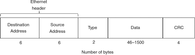
EXHIBIT 6.12 Ethernet II Frame Format
Exhibit 6.12 shows the format of an Ethernet MAC frame, primarily for purposes of comparison to the IEEE frame. The fields and their functions are:
- Preamble. Used for clock synchronization; employs the bit pattern 10101010…10101011 8 octets.
- Destination address (DA). 48-bit MAC address of the station that should receive this frame. An all-1s address (ff-ff-ff-ff-ff-ff) is the broadcast address, indicating that all stations should receive this message.
- Source address (SA). 48-bit MAC address of the station sending this frame.
- Protocol identifier (PID). Indicator of the protocol information transported in the Information field. Sample values include 2048 and 2054 to indicate the Internet Protocol (IP) and Address Resolution Protocol (ARP), respectively. 2 octets.
- Information. Protocol data unit from the protocol identified in the PID field. 46 to 1500 octets. (It is the responsibility of the higher layer to ensure that there are at least 46 octets of data in the frame.)
- Frame check sequence (FCS.). Remainder from CRC-32 calculation used for bit error detection. 4 octets.
The point in comparing the frame formats of Ethernet and 802.3 is to demonstrate that the two specifications are, in fact, different. It is a minor thing, perhaps, and a common misnomer in the industry to refer to IEEE 802.3 Ethernet, but it is an important difference to both a network administrator and a security professional.
In particular, if one LAN device only understands Ethernet encapsulation, it will not be able to communicate successfully with another LAN device that only understands IEEE 802.3 encapsulation. Both devices, however, can share the same medium backbone. A NetWare server running the Internetwork Packet Exchange (IPX) network layer protocol over IEEE 802.3 frames, for example, could easily share the network with a UNIX host running IP over Ethernet, but it maintains some immunity from attack by an IP host for the NetWare server.
6.5.5 IEEE 802.5 Token-Ring Standard.
The IEEE 802.5 token-ring standard is based on the IBM product of the same name. Both the standard and the product date back to about 1985.
The token ring has a logical ring topology, although it is built as a physical star. Designed to operate with STP or UTP cable, most current implementations operate at speeds of 16 Mbps or higher. The 802.5 MAC is essentially the same as the token passing scheme described in Section 6.4.2. The fields of the MAC frame (see Exhibit 6.13) are:

EXHIBIT 6.13 IEEE 802.5 Token and Frame Formats
- Start delimiter (SD). Marks the actual beginning of the transmission. Bit pattern JK0JK000, where J and K represent special symbols on the line.7 1 octet.
- Access control (AC). Indicates whether this transmission is a token (i.e., no data) or a frame (i.e., contains data). This field also contains information about the priority of this transmission. 1 octet.
- Frame control (FC). Indicates if this frame carries LLC (and higher-layer) data or MAC management information; if it is MAC-specific information, this field also indicates the MAC frame type. 1 octet.
- Destination address (DA). 48-bit MAC address of the station to which this frame is intended.
- Source address (SA). 48-bit MAC address of the station sending this frame.
- Routing information (RI). An optional field, used only in multiple-ring networks utilizing source routing and in which the intended receiver is on a different ring than the transmitter. In source routing, the transmitter can specify the intended path of this frame, designating up to eight intermediate networks.8 0 to 18 octets.
- Information (INFO). Contains an LLC frame or MAC management information. No maximum length is specified by the standard, but the length of this field will be limited by the time required to transmit the entire frame, controlled by the token holding time parameter.
- Frame check sequence (FCS). Remainder from a CRC-32 calculation to detect bit errors. 4 octets.
- End delimiter (ED). Demarks the end of the transmission, with the bit pattern JK1JK1IE, where J and K are as described in the previous SD field. The I-bit indicates whether this frame is the last frame of a multiple-frame sequence and the E-bit indicates whether a bit error was detected by the receiver (E); these bits are cleared by the original sender. 1 octet.
- Frame status (FS). The bit pattern AC00AC00; these bits indicate whether the frame's destination address was recognized by any station on the network (A) and whether this frame was successfully copied by the intended receiver (C). 1 octet.
As shown, a token comprises just three octets, the SD, AC, and ED fields. A station sends a frame whenever there is user data or MAC information to send. The station must wait until it receives a token before it can generate a frame.
The transmitting station is responsible for generating a new token after it transmits a single frame. Recall that the transmitted bits come back to the sender, and it is this station that removes the bits from the network. According to the original standard, the transmitter will send a token after sending all of the bits of the frame and must wait until it has seen at least the returning SA field to verify that it is, in fact, removing its own frame from the network. Optionally, early token release allows the transmitter to generate a new token immediately after finishing sending the bits from its frame, even if the SA field has not yet returned. This latter option was developed to improve performance in very large token ring environments, such as the American National Standards Institute (ANSI) FDDI standard.
Today, 802.5 token rings are primarily limited to IBM environments, and there is a lot to be found there. FDDI is more commonly found in multibuilding campus environments, used as a backbone to interconnect Ethernet/802.3 networks. FDDI is being phased out; the last FDDI product vendor dropped out of the marketplace in 1999.
6.5.6 IEEE 802.2 LLC Standard.
The IEEE 802.2 LLC protocol was intended to provide a common interface between 802 LAN MACs and higher-layer applications. With the LLC, the underlying MAC scheme is transparent to the application just as the application is transparent to the MAC.
The LLC was designed to support any number of services, the most common being an unacknowledged connectionless service (primarily used in contention networks) and an acknowledged connection-oriented service (primarily used in token ring environments).
The LLC is loosely based on the Higher-layer Data Link Control (HDLC) bit-oriented protocol in both operation and frame format (see Exhibit 6.14). The LLC frame appears in the Information field of a MAC frame. The first two fields of the LLC header are the Destination Service Access Point (DSAP) and the Source Service Access Point (SSAP) fields, originally intended to identify the higher-layer services at the source and destination node. This is similar in concept to ports in TCP/UDP but was never well implemented, and the DSAP and SSAP values are typically the same. The third field is the Control field, identifying the type of frame.

EXHIBIT 6.14 IEEE 802.2 LLC Frame Transporting SNAP Header (which in turn indicates IEEE organization and EtherType protocol identifiers)
The Subnetwork Access Protocol (SNAP) is an IEEE 802 (ISO 8802) protocol that can be used to identify any protocol created by any agency, and is commonly used above the LLC layer. In this case, the SNAP header immediately follows the LLC header. Use of SNAP is indicated by the LLC fields when both DSAP and SSAP fields are set to a value of 170 (octal aa) and the Control field is set to a value of 3 (octal 03) to indicate that is an Unnumbered Information frame.
The SNAP header has two fields. The 3-byte Organizationally Unique Identifier (OUI) field refers to the organization that developed either the higher layer protocol or a way to refer to the protocol. The 2-byte Type field identifies the protocol using the Organization-defined number.
IP and ARP provide a common sample use of SNAP. The common format of a SNAP header encapsulating these protocols would be to set the OUI value to 0 (0 × 00-00-00) to identify IEEE/ISO as the organization. The Type field would then use the EtherType values of 2048 (0×08-00) and 2054 (0 × 08-06) to indicate use of IP and ARP, respectively.
6.5.7 Summary.
This section has covered the important LAN standards governing what is most likely to be seen in the industry today. Table 6.1 summarizes some of the discussion about the most common LAN topologies, media, MAC schemes, and standards.
6.6 INTERCONNECTION DEVICES.
LAN interconnection devices are used to attach individual LANs to each other to build a large enterprise network. They can also interconnect LAN components across a WAN and provide LAN access to the Internet. Several types of such devices are used for LAN interconnections, including hubs, switches, bridges, and routers. The major distinction between these devices is the OSI layer at which they operate, and all are discussed in the next sections.
6.6.1 Hubs.
Hubs are used to build physically star-wired LANs, using media that are basically point to point in nature (such as UTP and fiber). Note that it is the internal wiring of the hub that determines its logical nature, so that a logical bus or ring LAN can be physically star-wired.
So-called Ethernet hubs support 10 and/or 100 Mbps Ethernet or 802.3 networks. Different hubs will have a different number of ports, generally ranging from 4 to 32. Hubs provide physical connectivity only; when a frame arrives on one port, the hub will broadcast the frame back out to all other ports, which simulates the broadcast bus environment. Multiple hubs can be interconnected to form reasonably large networks.
TABLE 6.1 LAN Characteristics

Token-ring hubs, generally called multistation access units (MAUs), look similar to Ethernet hubs but have different internal wiring. When an MAU receives a transmission on one port, it merely forwards that transmission, a bit at a time, to the next port sequentially on the MAU. In this way, it simulates the ring environment.
6.6.2 Switches.
Switches are generally employed in the CSMA/CD environment and extend the capabilities of a hub. A switch operates at a combination of PHY and MAC layers. In addition to providing physical connectivity like a hub, a switch learns the MAC address of all stations attached to it. When a frame arrives on a switch port, the switch looks at the destination MAC address and places the frame on the port associated with that address (which might be the port leading to another switch).
Switches are used primarily to improve performance. Given the scenario described earlier, multiple stations can transmit simultaneously without collision. Furthermore, switches can operate in full-duplex mode, meaning that a single station can both transmit and receive at the same time. A 10 Mbps switched Ethernet LAN, for example, can achieve performance similar to that of a 100-Mbps hubbed Ethernet LAN. (This is a real boon in those environments where it is not viable to upgrade 10-Mbps NICs and wiring.)
There is a very subtle security ramification to the use of switches versus hubs. In particular, if a user places a packet sniffer on a hubbed LAN, the sniffer will see every frame because the hub simulates the broadcast environment. A packet sniffer on a switched network will not be as effective; it will only pick up those frames that are specifically addressed to the LAN broadcast address.
6.6.3 Bridges.
A bridge provides a point-to-point link between the two LANs, usually those employing similar MAC schemes. Bridges operate at the MAC layer, and their operation is controlled by the MAC address.
Ethernet environments commonly employ learning bridges. In a very simple case, consider a bridge interconnecting two LANs, #1 and #2 (see Exhibit 6.15). When any LAN station sends a frame, both destination and source MAC addresses are included in the transmission. As frames appear on the networks, the bridge sees all of the source addresses and builds a table associating the MAC addresses with one LAN or the other, eventually learning the location of all of the network's stations. This process is sometimes called backward learning because the bridge learns the location of stations that transmit.
A bridge is a simple frame store-and-forward device. Like all stations on the LAN, a bridge examines the destination address of any transmitted frames. If a transmission on LAN #1 contains a destination address of a station on LAN #2, the bridge will forward the frame. If a transmission contains an unknown destination address, the bridge will also forward the frame.

EXHIBIT 6.15 Two LANs Interconnected via a Bridge
Although a bridge bases its decisions on the MAC address, it is not an intelligent device; that is, it knows that a station with a particular MAC address is in one direction or another, but it does not know precisely where that station is. Because bridges have to build tables containing all of the stations' addresses that they learn, bridges do not scale particularly well to large networks. Bridges also extend the broadcast domain (i.e., if a frame transmitted on LAN #1 is sent to the broadcast address, it will be forwarded to LAN #2).
6.6.4 Routers.
A router is conceptually similar to a bridge in that it is also a store-and-forward device. A router, however, works at the Network Layer and is therefore a much more powerful device than a bridge. As Exhibit 6.16 shows, every LAN device has both a MAC (hardware) and Network Layer (software) address (in this case, IP is the sample Network Layer address). Because Network Layer addresses are hierarchical, the networks themselves have a network identifier number (the NET_ID in Exhibit 6.16). Network Layer addresses are well suited to environments where intermediate devices have to find a best route between networks.
Like a bridge, a router is considered to be just another station on a LAN to which it is attached. If the router sees a transmission on LAN #1 containing a destination address of a station on another network, it will route the packet to the correct destination network, even if that means going through another router to get there.
This example also demonstrates another major difference between bridges and routers. In a bridged environment, a station on LAN #1 sends a frame to some MAC address and has no knowledge of whether the intended destination is on the same LAN or not; the bridge will forward the frame if necessary, but this is all transparent to sender and receiver. In a routed environment, however, the sender can tell if the receiver is on the same or different network merely by examining the destination network address. In fact, the router only gets involved if the packet has to leave the local network; that is why in an IP environment, for example, an address of a default gateway (router) has to be provided.
Routers also limit the broadcast domain. If a station on LAN #1 transmits a frame using the broadcast MAC address, the frame goes no further than the router.
Routers build their routing tables very differently than bridges. Whereas bridges learn the relative location of a station by observing a frame's source address, packets learn the Network Layer address by the use of routing protocols that allow groups of routers to exchange routing information.9
6.6.5 Summary.
Hubs, switches, bridges, and routers are all commonly employed LAN interconnection devices. These are tools in the kit of everyone who works with LANs, as the building blocks of everything from small and intermediate-size local networks to large enterprise networks and the global Internet.
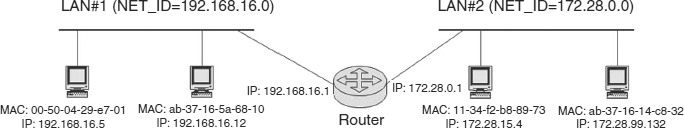
EXHIBIT 6.16 Two LANs Interconnected via a Router
6.7 NETWORK OPERATING SYSTEMS.
Just as an operating system manages computer resources, a network operating system (NOS) provides the software that controls the resources of a LAN. NOSs generally comprise software that provides at least these functions:
- Hardware drivers are the software that allows the NOS to communicate with the NIC.
- Communications software allows applications running on different LAN nodes to communicate.
- Services are the functional aspects of the NOS and the reason that people use a LAN in the first place. Sample services include file services (file sharing), print services (commonly shared printers), message services (e-mail), communication services (LAN access to the Internet), and fax services (commonly shared facsimile).
NOSs are typically classified as being peer to peer or client/server. A peer-to-peer LAN allows any LAN node to communicate with any other LAN node, and any LAN node can provide services to other nodes. In a client/server (or server-based) environment, every node is either a client or a server. In this scenario, servers are special nodes that offer services to other servers or to clients, while clients are the ordinary end-user workstations. Clients can only communicate with a server.
When evaluating or investigating the security of a LAN, the software is the most common point of exposure, vulnerability, and exploitation, particularly for remote attacks.
Some sample NOSs include:
AppleTalk. Apple Macs have come with integrated LAN capabilities since their inception. Originally using a scheme called LocalTalk, AppleTalk is a peer-to-peer network running over a 10-Mbps CSMA/CD LAN. The Network Layer protocol historically associated with AppleTalk is called the Datagram Delivery Protocol (DDP). Current versions of MacOS networking support IP.
Microsoft Networking. Microsoft operating systems have come with LAN capabilities since Windows for Workgroups (WfW or Windows 3.11). Employing a nonroutable protocol called the NetBIOS Extended User Interface (NetBEUI), Windows client systems (Windows 3.11, 95, 98, 2000, and XP) can be easily used to build an inexpensive, simple peer-to-peer LAN for file and print sharing. NetBEUI is nonroutable because it does not provide an addressing mechanism to allow interconnected yet distinct NetBEUI subnetworks; if two NetBEUI networks are attached in any way, they will appear to be one large network. (This is why the hard drive of improperly configured Windows systems can be viewed from across the Internet.)
Microsoft Windows NT/Windows 2000/Windows 2003 Server. If not the most widely deployed NOS today, Windows NT Server and the more current Windows 2000/2003 Server is certainly the fastest growing. Windows NT is a somewhat nontraditional client/server NOS. Servers run the Windows NT/W2K Server OS and act like any other server. Clients can run any Windows OS, including Windows 3.11, 95, 98, 2000 Professional, or NT Workstation; the clients themselves can form a peer-to-peer network.
Novell NetWare. Perhaps the best-known client/server NOS. In the early 1990s, NetWare had over 70 percent of the NOS market, but Novell today is struggling to stay in business. The Network Layer protocol associated with classical NetWare is the Internetwork Packet Exchange (IPX) protocol. In the latest versions of NetWare, Novell abandoned IPX in favor of IP.
UNIX. TCP/IP has been the network communications protocol for UNIX systems since 1984. In the TCP/IP suite, any system can run server (daemon) software to provide services to other systems, so that any system can be either client or server.
6.8 SUMMARY.
Exhibit 6.17 shows a possible network design that includes many of the elements that have been described in this chapter (and a few that have not). This network's router provides the interface to the Internet and is attached via some sort of dedicated connection, such as a point-to-point 56 KBps or T1 (1.544 Mbps) leased line, frame relay, or digital subscriber line.
In this scenario, the router is physically located at the main site. From a security perspective, the organization may segment its network into an external and internal side, the internal being protected by a firewall.10 The external network includes the router, public Web server, and firewallThose three systems are interconnected through a hub to which they each attach via a Cat. 5 UTP cable. In this scenario, the hub could actually implement 10BASE-T or 100BASE-T Ethernet, or even a token ring.
The external and internal networks are connected through the firewall, which, in this case, will have two NICs. The two networks are separate and distinct; the firewall does not extend the broadcast domain of either network, and, in fact, these two networks would have different IP network numbers.

EXHIBIT 6.17 LAN Scenario
The internal network at the main site is a collection of servers and user workstations that are interconnected via a set of switches. In this example, these are 8-port 100-Mbps Ethernet switches. Since there are more than 8 devices, the switches themselves need to be interconnected. There are several options for that:
- Stackable switches physically attach to each other, extending the switch's backplane to create a larger switch (in this case, a 16-port switch).
- An optical fiber link can be used to interconnect the switch, usually at backplane speeds in the 1+-Gbps range.
- A UTP link might be used to interconnect the switches via two of the 100-Mbps ports.
To connect the LAN in Building #2 with the LAN at the main site, a point-to-point connection between a pair of bridges would suffice. In this case, the buildings are several kilometers apart, necessitating use of optical fiber.
In Building #2, there is another hub-based LAN, with a laptop using wireless technology, communicating with an access node that is also attached to the hub.
This chapter has only skimmed the surface of LAN concepts, standards, and technologies. Their study is important to the security professional, however, Because LANs are the basis of all networking. As a network of networks, the Internet comprises millions of local networks. This chapter indicates many of the points of potential vulnerability or compromise in a system.
6.9 WEB SITES
10 Gigabyte Ethernet Alliance
www.10gea.org/10GEA White Paper_0502.pdf
Gast, M. “Wireless LAN Security: A Short History.” (2002).
www.oreillynet.com/pub/a/wireless/2002/04/19/security.html
IEEE LAN/MAN Standards
http://grouper.ieee.org/groups/802/
LAN/MAN Protocols
www.cisco.com/en/US/docs/internetworking/technology/handbook/Intro-to-LAN.html
6.10 FURTHER READING
Mikalsen, A., and P. Borgesen. Local Area Network Management, Design and Security: A Practical Approach. Hoboken, NJ: John Wiley & Sons, 2002.
Riley, S., and R. A. Breyer. Switched, Fast, and Gigabit Ethernet, 3rd ed. Indianapolis: New Riders Publishing, 1998.
Stallings, W. Local and Metropolitan Area Networks, 6th ed. Upper Saddle River, NJ: Prentice-Hall, 2000.
6.11 NOTES
1. It is an interesting point of trivia to note that the original frequency-hopping spread spectrum technique was invented by none other than Hollywood star Hedy Lamarr in 1940.
2. Since CSMA/CD transmits with a probability of 1, it is sometimes referred to as being 1-persistent.
3. As an aside, although the station can experience 16 collisions, the probability of transmission will never fall below 1/1024, or 2−10, since Ethernet and IEEE 802.3 do not allow more than 1024 devices on the network. This is the source of the word “truncated” in the name of the scheme.
4. Up-to-date status information about the 802 committee can be found at the LAN/MAN Standards Committee Web site at http://grouper.ieee.org/groups/802/.
5. A WG will go into hibernation when there are no new projects to undertake. This status indicates a WG that has reached status quo.
6. A WG is disbanded when it is considered that there is no more work for the IEEE to undertake in this topic area.
7. The term “special symbol” requires some explanation. The token ring uses a PHY signaling scheme to transmit 1s and 0s called Differential Manchester. In this signaling scheme, the signal is at a positive voltage for half of the bit time and at a negative voltage for the other half of the bit time, meaning that each bit has a sum total of 0 volts (resulting in what is sometimes called DC balancing). The J and K symbols are Differential Manchester code violations, where one symbol is at negative voltage for an entire bit time and the other at positive voltage for an entire bit time. These code violations have the benefit of being able to indicate special events and can be used for synchronization. J and K symbols are always used in pairs to maintain DC balancing.
8. Source routing is a very rarely used option in IP and is, in fact, a security problem; firewall administrators routinely set up filters to block IP packets with source routing. Source routing in an 802.5 network, however, is a normal feature and is not considered to be a security threat because this information has no impact on the WAN.
9. In the IP environment, common routing protocols include the Border Gateway Protocol (BGP), Open Shortest Path First (OSPF), and Routing Information Protocol (RIP).
10. This is a very simplistic firewall design with the internal and external network. The focus of this diagram is on the LAN components, however, rather than the specific security architecture.