
CHAPTER 5
DATA COMMUNICATIONS AND INFORMATION SECURITY
Raymond Panko
5.2.3 Firm's Wide Area Networks (WANs)
5.3 NETWORK PROTOCOLS AND VULNERABILITIES
5.4.2 Layered Standards Architectures
5.4.3 Single-Network Standards
5.4.4 Internetworking Standards
5.6 TRANSMISSION CONTROL PROTOCOL (TCP)
5.6.1 Connection-Oriented and Reliable Protocol
5.6.4 Octets and Sequence Number
5.8 TCP/IP SUPERVISORY STANDARDS
5.8.1 Internet Control Message Protocol (ICMP)
5.8.2 Domain Name System (DNS)
5.8.3 Dynamic Host Configuration Protocol (DHCP)
5.8.4 Dynamic Routing Protocols
5.8.5 Simple Network Management Protocol (SNMP)
5.9.4 Other Application Standards
5.1 INTRODUCTION.
Sometimes, an attacker can simply walk up to a target computer. In most cases, however, attackers must use networks to reach their targets. Some attacks even aim at networks, trying to bring down local area networks, wide area networks, and even the global Internet. This chapter provides an overview of networking to help readers of this Handbook when they come across networking concepts in other chapters or in other context. This chapter covers a limited number of networking concepts. Specifically, it focuses on aspects of networking that are most relevant to security.
Before beginning, readers should note three important pieces of terminology that pervade the chapter.
- This chapter often uses the term octet, which is a byte—a collection of eight bits. Networking grew out of electrical engineering, where octet is the preferred term.
- The second term is host. Any device attached to the global Internet is called a host. This includes large server hosts, of course, but it also includes client PCs, personal digital assistants, mobile telephones, and even Internet-accessible coffeepots.
- We will distinguish between the terms internet and Internet; the latter refers to the global Internet. However, internet spelled in lower case is either the Internet layer in the TCP architecture (see Section 5.6) or a collection of networks that is not the global Internet.
5.2 SAMPLING OF NETWORKS.
This section looks briefly at a series of increasingly complex networks, giving the reader a high-level overview of what networks look like in the real world.
5.2.1 Simple Home Network.
Exhibit 5.1 shows a simple home PC network. The home has two personal computers. The network allows the two PCs to share files and the family's single laser printer. The network also connects the two computers to the Internet.
5.2.1.1 Access Router.
The heart of this network is its access router. This small device, which is about the size of a hardback book, has five functions.
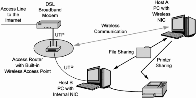
EXHIBIT 5.1 Simple Home Network
- It is a switch. When one PC in the home sends messages (called frames) to the other computer, the switch transfers the frames between them
- The access router is a wireless access point (WAP), which permits wireless computers to connect to it. Host A connects to the access router wirelessly.
- A router connects a network to another network—in this case, the global Internet.
- To use the Internet, each computer needs an Internet Protocol (IP) address. We will see later that IP is the main protocol that governs communication over the Internet. The access router has a built-in Dynamic Host Configuration Protocol (DHCP) server that gives each home PC an IP address.
- The access router provides network address translation (NAT), which hides internal IP addresses from potential attackers. Some access routers also have a firewall for added security.
Wireless access points are dangerous because radio signals spread widely. If the user does not configure strong security in the access point and all wireless stations, anyone will be able to read the user's traffic and do mischief.
NAT provides a surprisingly large amount of protection. Even people with single PCs may find it attractive to use an access router to gain this protection.
5.2.1.2 Personal Computers.
Each of the two PCs needs circuitry to communicate over the network. Traditionally, this circuitry came in the form of a printed circuit board, so the circuitry was called the computer's network interface card (NIC). In most computers today, the circuitry is built into the computer; there is no separate printed circuit board. However, the circuitry is still called the computer's NIC.
In this small network, the two computers share their files. Given the wireless access capability of the network, drive-by hackers could potentially read shared files as well. File sharing without strong wireless security is dangerous. It is important to set up Wi-Fi Protected Access (WPA) or 802.11i security in pre-shared key (PSK) mode on both the access router/access point and each of the client PCs.
It is important to configure the PCs for security. Although NAT by itself is strong, and although a growing number of access routers also provide stateful-inspection firewalls as well (see Chapter 26 in this Handbook), some attacks will inevitably get through to the personal computers. The PCs must have strong firewalls, antivirus programs, and antispyware programs (see Chapter 41); and they must be updated automatically when security patches are released by the operating system vendor and by application program vendors (see Chapter 40).
5.2.1.3 UTP Wiring.
In Exhibit 5.1, Host B connects to the access router via copper wiring. Specifically, it uses four-pair unshielded twisted pair (UTP) wiring. As Exhibit 5.2 shows, a UTP cord contains eight copper wires organized as four pairs. The two wires of each pair are twisted around each other. The RJ-45 connectors at the ends of a UTP cord look like RJ-11 home telephone connectors but are a little wider. (RJ means Registered Jack and originally referred to Bell System order codes; it is now defined by the Administrative Council for Terminal Attachment, ACTA.)
5.2.1.4 Internet Access Line.
The home network needs an Internet access line to connect the home to the Internet. In Exhibit 5.1, this access line is a Digital Subscriber Line (DSL) high-speed access line, and the home connects to this access line via a small box called a DSL modem. (The DSL modem connects to the access router via a UTP cord; it connects to the wall jack via an ordinary telephone cord.) Other Internet access technologies include slow telephone modems, fast cable modems, and even wireless access systems. Most of these technologies are called broadband access lines. In general, broadband simply means “very fast,” although in radio transmission it describes a wide range of frequencies.
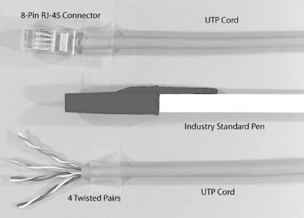
EXHIBIT 5.2 Unshielded Twisted Pair Wiring (UTP) Cord
5.2.2 Building LAN.
The home network shown in Exhibit 5.1 is a local area network (LAN). A LAN operates on a customer's premises—the property owned by the LAN user. (For historical reasons, “premises” is always spelled in the plural.) In the case of the home network, the premises consist of the user's home or apartment. Exhibit 5.3 shows a much larger LAN. Here, the premises consist of a corporate multistory office building.
On each floor, computers connect to the floor's workgroup switch via a UTP cord or a wireless access point. The workgroup switch on each floor connects to a core switch in the basement equipment room. The router in the basement connects the building LAN to the outside world.
Suppose that Client A on Floor 1 sends a frame to Server X on Floor 2. Client A sends the frame to Workgroup Switch 1 on the first floor. That workgroup switch sends the frame down to the core switch in the basement. The core switch then sends the frame up to Workgroup Switch 2, which passes the frame to Server X.
UTP is easy to wiretap, allowing attackers to read all packets flowing through the cord. Telecommunications closets should be kept locked at all times, and cords should be run through thick metal wiring conduits wherever possible. (For more details of physical and facilities security, see Chapter 23.)
UTP also generates weak radio signals when traffic flows through it. It is possible to read these signals from some distance away using highly specialized equipment.
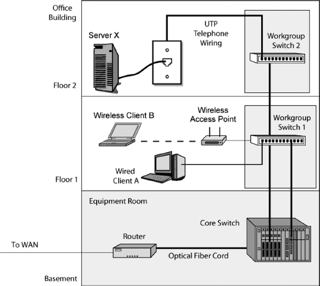
EXHIBIT 5.3 Building LAN
Typically, however, eavesdroppers do not even need to tap wires. In most building LANs, anyone entering the building can plug a notebook into any wall jack with a UTP cord. This gives them access to the network without having to do more sophisticated forms of wiretapping. Most switches today have 802.1X capability that requires any device connecting to a wall jack to authenticate itself before being allowed to transmit beyond the switch.
For more extensive details of LAN security, see Chapter 25 in this Handbook.
5.2.3 Firm's Wide Area Networks (WANs).
Although LANs operate within a company's premises, wide area networks (WANs) connect different sites—usually within a single corporation. Corporations do not have the regulatory rights-of-way needed to run wires though public areas. For WAN service, companies must use companies called carriers that do have these rights-of-way.
Exhibit 5.4 shows that most firms use multiple-carrier WANs. In the exhibit, some sites in this company are connected by point-to-point leased lines from a telephone company. The companies also subscribe to switched network services that deliver frames between several sites. The exhibit shows that these switched network services use the Frame Relay technology. The company uses two separate Frame Relay networks—one to connect its own sites to one another and another to connect it to another firm.
Carrier technology is widely assumed by security professionals to have good security. Unlike the Internet, which allows anyone to connect to it, only commercial firms may connect to carrier WANs. This makes attacker access very difficult. However, attacker access is not impossible. For example, if an attacker hacks a computer owned by the carrier (or even by a customer), this breach may permit access.
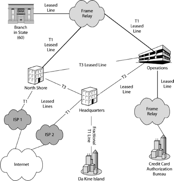
EXHIBIT 5.4 Wide Area Networks (WANs)
In addition, the carrier alone knows how it routes traffic through its network. This should stymie attackers even if they somehow get access to the network. However, such security through obscurity is considered a very bad thing by security professionals because it is possible for attackers who hack carrier computers to get access to routing information. (Attackers usually have much simpler attack vectors; see Chapters 15 and 19 in this Handbook for more details.)
5.2.4 Internet.
By the end of the 1970s, there were many LANs and WANs in the world. Many of the WANs were nonprofit networks that connected universities and research institutions. Unfortunately, computers on one network could not talk to computers on other networks. To address this problem, the Defense Advanced Research Projects Agency (DARPA) created the Internet. By definition, an internet is a “super network” that connects individual networks together. Later, commercial networks were allowed to join the Internet, and it became the Internet we know today.
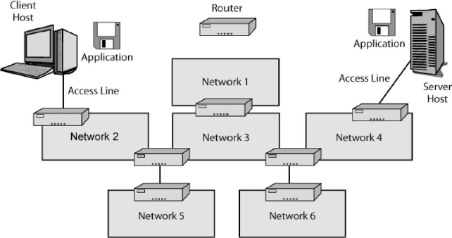
EXHIBIT 5.5 Internet
Exhibit 5.5 shows that devices called routers connect the individual networks together. Initially, these devices were called gateways. The term “gateway” was used instead of “router” in some early standards, but most vendors have now adopted the name “router.” One major exception is Microsoft, which still tends to call routers gateways.
Any computer on any network on the Internet can send messages to any computer on any other network on the Internet. In single LANs and WANs, messages are called frames. On the Internet, the messages that travel all the way from one computer to another across the Internet are called packets.
Exhibit 5.6 shows that the packet travels all the way from the source host to the destination host. Along the way, it is carried inside a different frame in each network.
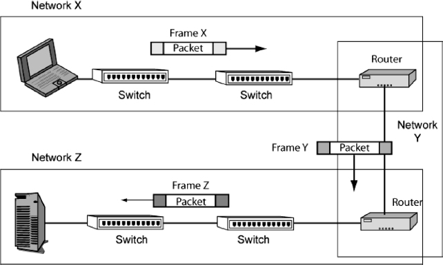
EXHIBIT 5.6 Frames and Packets
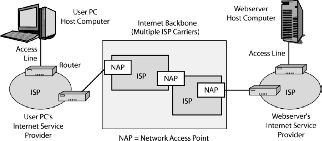
EXHIBIT 5.7 Internet Service Providers (ISPs)
In Network X, the packet travels inside Frame X; in Network Y, the packet travels inside Frame Y; and in Network Z, the packet travels inside Frame Z.
The global Internet uses transmission standards that are known as the Transmission Control Protocol/Internet Protocol (TCP/IP) standards. In addition, many firms build separate internal TCP/IP internets for their own communication. These internal networks are called intranets to distinguish them from the Internet. We will use the term internet with a lower-case i to designate any internet that is not the global Internet.
Initially, security on intranets was comparatively light because it was assumed that external attackers would have a difficult time getting into corporate intranets. However, if a hacker takes over an internal computer connected to the intranet, light security becomes a serious problem. Consequently, most firms have been progressively hardening their intranet security.
Exhibit 5.7 shows that individual homes and corporations connect to the Internet via carriers called Internet Service Providers (ISP). The Internet has many ISPs, but they all connect at centers that usually are called Network Access Points (NAPs). These connections permit any host on any ISP to send packets to any host on any other ISP.
ISPs are commercial organizations run for profit, that there is no central point of control over the Internet's operation, although there is centralized control over the naming of Internet host computers (e.g., cnn.com.).
When the Internet was designed in the late 1970s, there was a conscious decision to promote openess and not to add the burdens of security. As a consequence of a lack of security technology and open access to almost anyone, the Internet is a security nightmare. Companies that transmit sensitive information over the Internet need to consider cryptographic protections. (See Chapters 7, 32, 33, 34, 35, and 37 in this Handbook for more details of cryptography and other means for achieving, security on networks.)
5.2.5 Applications.
Although both networks and internets are important, the only things that users care about are applications. Personal applications include the World Wide Web, e-mail, and instant messaging, among many others. Corporations use some of these applications, but they also use many business-specific applications, such as accounting, payroll, billing, and inventory management. Often, business applications are transaction-processing applications, which are characterized by high volumes of simple repetitive transactions. The traffic volume generated by transaction-processing and other business-oriented applications usually far outweighs the traffic of personal applications in the firm. (See Chapter 30 in this Handbook for details of e-commerce security.)
All programs have bugs, including security vulnerabilities. There are many applications, and keeping track of application vulnerabilities and constantly patching many applications is an enormous task that is all too easy to put off or complete only partially. (See Chapter 40 for an overview of patch management.) Also, each application must be configured with options that have high security, and security must be managed on each application (e.g., antivirus and spam blocking in e-mail). (See Chapter 20 for a review of spam and antispam measures.)
5.3 NETWORK PROTOCOLS AND VULNERABILITIES.
The products of different network vendors must be able to work together (interoperate). This is possible only if there are strong communication standards to govern how hardware and software processes interact. With such standards, two or more programs can interoperate effectively.
Standards raise three security issues. One is the standard itself. For instance, the TCP standard discussed later in this chapter is difficult to attack because an attacker cannot send a false message unless he or she can guess the sequence number of the next message. This normally is very difficult to do. However, if the attacker sends an RST (Reset) message, which terminates a connection, this protection is greatly reduced. In fact, it is fairly easy to send RST messages that close legitimate open connections.
A second issue is security built into the standard. Most standards were created without security, and security was added only in later versions, sometimes in an awkward way. For instance, IP, which is the main protocol for delivering packets over the Internet, originally had no security. The IPsec standards were created to address this weakness, but IPsec is burdensome and not widely used.
A third issue is the security of the implementation of standards in vendor products. Most attacks that aim at standards weaknesses attack vendor products that have security vulnerabilities unrelated to the protocols they implement.
5.4 STANDARDS.
Networks and network security are deeply dependent on standards.
5.4.1 Core Layers.
Standards are complex, and when people deal with complex problems, they usually break these problems into smaller parts and have different specialists work on the different parts. Exhibit 5.8 shows that standards are divided into three core layers that collectively have the functionality needed to allow an application program on one network in an internet to interoperate with another program on another computer on another network.
EXHIBIT 5.8 Three Standards Core Layers
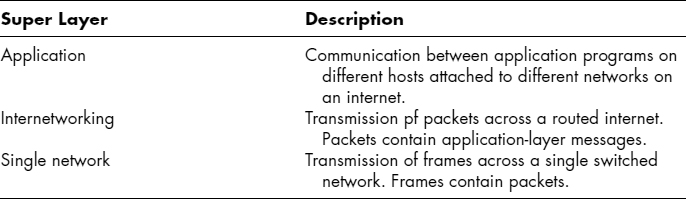
At the application core layer, the two applications must be able to interact effectively. For instance, in World Wide Web access, the two application programs are the browser on the client PC and the Web server program on the Web server. The standard for Web interactions is the Hypertext Transfer Protocol (HTTP). Both the browser and the Web server applications have to send messages that comply with the HTTP standard.
The middle layer is the internet core layer. Standards at this layer govern how packets are delivered across a routed internet. One of the main standards at the internet core layer is the Internet Protocol (IP). We will see other internetworking standards later.
The lowest core layer is the single-network core layer. Standards at this layer govern the transmission of frames across the switches and transmission lines in a single switched network (a LAN or WAN).
5.4.2 Layered Standards Architectures.
Standards are created by standards agencies. These standards agencies first create detailed layering plans for creating standards. These specific layering plans are called layered standards architectures. Afterward, standards agencies create standards in the individual layers. Exhibit 5.9 shows two popular layered standards architectures and relates these standards architectures to the three core layers we saw earlier.
The Internet Engineering Task Force (IETF) is the standards agency for the Internet. Its standards architecture is called TCP/IP—a name taken from two of its most important standards, TCP and IP. Exhibit 5.9 shows that TCP/IP has four layers. The bottom layer, the subnet access layer, corresponds to the single-network core layer. The top layer, in turn, is the application layer, which corresponds to the application core layer. The two middle layers—the internet and transport layers—correspond to the internet core layer. TCP/IP focuses primarily on internetworking. Dividing this core layer into two TCP/IP layers permits greater division of labor in standards development.
The other standards architecture shown in the figure is OSI, which is rarely spelled out by its full name, the Reference Model of Open Systems Interconnection. OSI is governed by two standards agencies. One is ISO, the International Organization for Standardization. The other is ITU-T, the International Telecommunications Union–Telecommunications Standards Sector. (The official names and the official acronyms do not match when the originated in different languages.)
Exhibit 5.9 shows that OSI divides the three core layers into a total of seven layers. OSI single networks use standards at two layers—the physical and data link layers.
EXHIBIT 5.9 Layered Standards Architectures
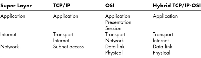
OSI's market dominance is so strong at the physical and data link layers that the IETF rarely develops standards at these layers. The “subnet access” indication in the TCP/IP framework basically means “Use OSI standards here.”
Which of these two standards architectures dominates? The answer is “Neither.” What nearly all firms use today is the hybrid TCP/IP-OSI standards architecture, which Exhibit 5.9 illustrates. This hybrid architecture uses OSI standards at the physical and data link layer and TCP/IP standards at the internet and transport layer. Corporations also use standards from some other standards architectures at the internet and transport layers, but TCP/IP standards dominate.
At the application core layer, the situation is complex. Both OSI and TCP/IP standards are used, often in combination. In fact, OSI standards often reference TCP/IP standards and vice versa. Although OSI and TCP/IP are often viewed as rivals, this is not the case at all. Several other standards agencies also create application layer standards, complicating the picture even further.
5.4.3 Single-Network Standards.
As just noted, OSI standards dominate in the two single-network layers—the physical and data link layers. Exhibit 5.10 shows how the physical and data link layers are related.
5.4.3.1 Data Link Layer.
The path that a frame takes through a single network is called the frame's data link. In Exhibit 5.10, the data link runs between Host A and Router R1. This data link passes through Switch X1 and Switch X2.
The source computer sends the frame to the first switch, which forwards the frame to the next switch along the data link, which forwards the frame further. The last switch along the data link passes the frame to the destination computer (or router, if the packet in the frame is destined for a computer on another network).
5.4.3.2 Physical Layer.
Physical layer standards govern the physical connections between consecutive devices along a data link. In Exhibit 5.10, these physical links are A–X1, X1–X2, and X2–R1. Earlier, we saw one popular transmission medium, unshielded twisted pair wire. UTP dominates in links between computers and workgroup switches (see Exhibit 5.3). UTP signals typically involve voltage changes. For instance, a high voltage may indicate a 1, while a low voltage may indicate a 0. (Actual voltage patterns usually are much more complex.)
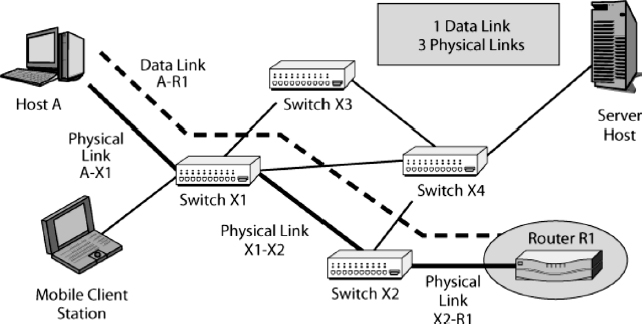
EXHIBIT 5.10 Physical and Data Link Layers
For longer distances and very high speeds, another popular transmission medium is optical fiber, which sends light signals through thin glass tubes. Optical fiber signals actually are very simple. In a clock cycle, the light is turned on for a 1 or off for a 0.
UTP cords act like radio antennas when they carry signals. Some of the signal always radiates out, allowing people to intercept UTP signals by placing devices near (but not touching) the cord. Intercepting and interpreting electromagnetic emissions from computing devices is called van Eck phreaking after the Dutch scientist Wim van Eck published a paper in 1985 demonstrating how to monitor and reconstitute leaked signals from cathode-ray terminals (CRTs). In contrast, optical fiber requires physically tapping into the fiber cords. Physical wiretapping can also be done with UTP, but as noted earlier, the easiest way to connect to a network via UTP usually is simply to bring a laptop computer into a company and plug it into any wall jack.
Wireless transmission uses radio waves. This permits mobile devices to be served in ways never before possible. Wireless transmission is used for both LAN and WAN transmission.
Radio signals spread widely, even when dish antennas are used. Consequently, it is very easy for eavesdroppers to listen in on radio transmissions and do other mischief. Radio signals must be strongly encrypted, and the parties must be strongly authenticated to prevent impostors from sending radio transmission.
Radio signaling is very complex. Most radio signaling uses spread spectrum transmission, in which the information is sent over a wide range of frequencies. Spread spectrum transmission is used to improve propagation reliability. Radio transmission has many propagation problems, such as interference from other sources. Many propagation problems occur only at certain frequencies. By spreading the signal across a wide spectrum of frequencies and doing so redundantly, the signal will still be intelligible even if there are strong problems at some frequencies.
The military uses frequency hopping spread spectrum (FHSS) transmission for security. Military spread spectrum transmission works in such a way that makes intercepting transmissions very difficult. Civilian spread spectrum transmission, in contrast, is designed to make connecting simple. Civilian spread spectrum transmission per se offers no security.
Switches spend almost all of their time forwarding frames. However, switches spend some of their time exchanging supervisory frames with one another to keep the network running efficiently. For example, in Ethernet (IEEE 802.3), which dominates LAN standards, if there are loops among the switches, the network will malfunction. If a switch detects a loop, it sends supervisory frames to other switches. The switches in the network then communicate until they determine how to close selected ports on certain switches to break the loop. This process is governed by the Spanning Tree Protocol (STP, part of IEEE 802.1) or the newer Rapid Spanning Tree Protocol (RSTP, defined in IEEE 802.1w and now part of IEEE 802.1D-2004).
Attackers can create attacks on the switches in a network by impersonating a switch and sending a flood of false messages to the network's real switches indicating the presence of a loop. The switches may spend so much of their time reorganizing the network that they will be unable to serve legitimate traffic. They also can attack several other supervisory protocols to make switches unavailable for processing normal frames. The 802.1AE standard is designed to limit switch-to-switch communication to authenticated switches.
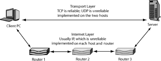
EXHIBIT 5.11 Internet and Transport Layer Standards
5.4.4 Internetworking Standards.
As noted earlier, the IETF divided the internetworking core layer into two layers—the internet and transport layers. Exhibit 5.11 shows how the two layers are related.
The internet layer forwards packets, hop by hop, among routers until the packet reaches the destination host. The main standard at the internet layer is the Internet Protocol (IP).
The designers of TCP/IP realized that they could not predict what services the single networks connecting routers would provide. IP was made a simple best-effort protocol, in order to assume minimal functionality in the single networks along the way. There are no guarantees that packets will arrive at all or, if they do arrive, that they will arrive in order.
To make up for the limitations of IP, a transport layer was added. The main standard designed for this layer, the Transmission Control Protocol (TCP), was created as a high-capability protocol that would fix any errors made along the way, ensure that packets arrived in order, slow transmission when the network became overloaded, and do several other things. For applications that did not need these capabilities, a simpler standard was created, the User Datagram Protocol (UDP).
5.5 INTERNET PROTOCOL (IP).
The Internet Protocol (IP) does two main things. First, it governs how packets are organized. Second, it determines how routers along the way move packets to the destination host. (Analogously, data link layer standards govern how frames are organized and how switches along the way move the frame across a single switched network.)
5.5.1 IP Version 4 Packet.
The main version of the Internet Protocol is Version 4 (IPv4). (There were no Versions 0, 1, 2, or 3). This version has been in use since its definition in 1981 and will continue to be used for many years to come, although IPv4 is intended to supercede it. Exhibit 5.12 shows the IPv4 packet's organization.
A packet is a long stream of 1s and 0s. The IP header normally is shown on several rows, with 32 bits on each row. The first row has bits 0 through 31; the next row shows bits 32 through 63 and so on.
The header is divided into smaller units called fields. Fields are defined by their bit position in the packet. For example, the first four bits comprise the version number field. These are bits 0 through 3. In IPv4, this field holds 0100, which is 4 in binary. The header length field comprises the next four bits (bits 3 through 7).
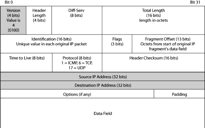
EXHIBIT 5.12 Internet Protocol (IP) Packet
5.5.1.1 First Row.
As just noted, the first field (bits 0 through 3) is the version number field. In IPv4, the value is 0100 (4). In the newer version of the Internet Protocol, IP Version 6 (IPv6), the value is 0110.
The next field is the header length field. This gives the length of the headers in 32-bit units. As Exhibit 5.12 shows, a header without options has five 32-bit lines, so this field will have the value 0101 (5 in binary).
The use of options is uncommon in practice. In fact, options tend to indicate attacks. Therefore, a value larger than 5 in the header length field indicates that the packet header has options and is therefore suspicious.
The 1-octet dif-serv (differential services) field was created to allow different services (priority, etc.) to be given to this packet. However, this field typically is not used.
The total length field gives the length of the entire IP packet in octets (bytes). Given the 16-bit length of this field, the maximum number of octets in the IP packet is 65, 536 (216). Most IP packets, however, are far smaller. The length of the data field is this total length minus the length of the header in octets.
5.5.1.2 Second Row.
If an IP packet is too long for a single network along the way, the router sending the packet into that network will fragment the packet, dividing its contents into a number of smaller packets. For assembly on the destination host, all fragment packets are given the same identification field value as in the original packet. The data octets in the original packets are numbered, and the number of the first data octet in the packet is given a fragment offset value (13 bits long). There are three flag fields (1-bit fields). One of these, more fragments, is set to 1 in all but the last packet, in which it is made 0. The information in these three fields allows the destination host to place the packets in order and know when there are no more packets to arrive.
IP fragmentation by routers is usually rare, and attackers can use fragmentation to hide attack information. Even if the first fragment packet is dropped by the firewall, other packets that do not have the signature information in the first header can get through. Therefore, IP fragmentation is suspicious.
5.5.1.3 Third Row.
The third line begins with an ominous-sounding time to live (TTL) field, which has a value between 0 and 255. The sending host sets the initial value (64 or 128 in most operating systems). Each router along the way decreases the value by 1. If a router decreases the value to 0, it discards the packet. This process was created to prevent misaddressed packets from circulating endlessly around the Internet.
To identify hosts, attackers will ping many IP addresses (as discussed in Section 5.8.1). A reply tells the attacker that a host exists with that IP address. In addition, by guessing the initial TTL value and looking at the TTL value in the arriving packet, the attacker can guess how many router hops separate the attacker's host from the victim host. Sending many pings to different IP addresses can help the attacker map the routers in the target network. Firms concerned with this might change their host operating systems' default TTL values to confuse attackers.
The data field of the IP packet may contain a TCP message segment, a UDP datagram message, or something else, such as the ICMP messages we will discuss in Section 5.8.1. A value of 1 in this field indicates that the data field is an ICMP message. In turn, 6 indicates a TCP segment, and 17 indicates that the data field contains a UDP header.
The header checksum field contains a value placed there by the sender. This number is determined by a calculation based on the values of other fields. The receiving internet process redoes the calculation. If the two numbers are different, then there must have been an error along the way. If so, the router or destination host receiving the packet will simply discard the packet. There is no retransmission, so IP is not reliable.
5.5.1.4 Source and Destination IP Address.
When you send a letter, the envelope has an address and a return address. The analogous addresses in IP headers are the source and destination IP addresses. Note that IP addresses are 32 bits long. For human reading, these 32 bits are divided into four 8-bit segments, and each segment's bits are converted into a decimal number between 0 and 255. The four segment numbers are then separated by dots. An example is 128.171.17.13. Note that this dotted decimal notation is a memory and writing crutch for inferior biological entities (people). Computers and routers work with 32-bit IP addresses directly.
Many forms of firewall filtering are based on IP addresses. In addition, many attackers spoof their packet's source IP address (i.e., replace the real IP address with a false IP address).
5.5.2 IP Version 6.
Although IP Version 4 is widely used, its 32-bit IP address size causes problems: It can address only 4, 294, 967, 296 (∼109) devices. This relatively small size limits the number of possible IP addresses. In addition, when IP addresses were distributed, most addresses were assigned to the United States because the Internet was invented there. In fact, some U.S. universities received more IP addresses than China.
To address the limitations of the 32-bit IP address size, anew version of the Internet Protocol was created. This was IP Version 6 (IPv6). (A Version 5 was defined, but it was never used.) Exhibit 5.13 shows the IPv6 packet organization.
One obvious change is that the IP addresses are much larger—128 bits. Each IP address, then, requires four 32-bit lines to write and is equivalent to ∼1038. This will provide IP addresses to allow almost every device to be a host on the Internet—including toasters and coffeepots. (To give you a sense of the scale of this enormous number, it is enough to address every single atom of water in a cube over 2 km on a side.)
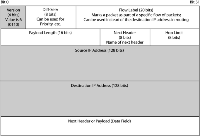
EXHIBIT 5.13 IP Version 6 Packet
The version number field is 4 bits long, and its value is 6 (0110). There also is a dif-serv field and a flow label field that is 20 bits long. These fields allow the packet to be assigned to a category of packets with similar needs. All packets in this category would be assigned the same flow label and would be treated the same way by routers. However, this capability is not widely used.
There is a hop limit field that serves the same function as the time to live (TTL) field in IPv4. The payload length, in turn, gives the length of the data field in octets.
A major innovation in IPv6 is the next header field. There can be multiple headers following the first header shown in Exhibit 5.13. For instance, IPsec security is implemented with a security header. Although options are unusual in IPv4, IPv6 uses additional headers extensively. The next header field tells what the next header is. Each additional header has a next header field identifies the next header or says that there is no next header.
5.5.3 IPsec.
IP, which was created in the early 1980s, initially had no security at all. Finally, in the 1990s, the Internet Engineering Task Force developed a general way to secure IP transmission. This was IP security, which normally is just called IPsec (eye-pea-seck′). IPsec functions by protecting a packet or most of a packet and sending the protected packet inside another packet. IPsec is a general security solution because everything within the data field of the protected packet is secure, including the transport and application layer information. This includes the transport message and the application message contained in the transport message. Originally developed for IPv6, it was extended to IPv4 as well, becoming a completely general solution.
5.6 TRANSMISSION CONTROL PROTOCOL (TCP).
As noted earlier, the Transmission Control Protocol (TCP) is one of the two possible TCP/IP protocols at the transport layer. Exhibit 5.14 shows the TCP message, which is called a TCP segment.
5.6.1 Connection-Oriented and Reliable Protocol.
Protocols are either connectionless or connection-oriented.
Connection-oriented protocols are like telephone conversations. When you call someone, there is at least tacit agreement at the beginning of the conversation that you are able to speak. (Such expressions as “Hold, please.” and “Can I call you back?” indicate an unwillingness to proceed at the moment.) Also, there is at least tacit agreement that you are done talking at the end of the conversation. (Simply hanging up is considered rude.)
Connectionless protocols, in turn, are like e-mail. When you send a message, there is no prior agreement, and after the message is sent, there is no built-in provision for a reply (unless you are one of those people who asks to be notified when the receiver reads the message).
Exhibit 5.15 shows a sample TCP connection. Three messages are sent to open a connection. The originator sends a TCP SYN segment to indicate that it wishes to open a TCP session. The other transport process sends back a TCP SYN/ACK segment that acknowledges the connection opening message and indicates that it is willing to open the connection. The originator then sends an ACK segment to indicate reception of the SYN/ACK segment.
Attackers can use TCP connection openings to execute denial-of-service attacks that make a server unable to respond to legitimate traffic. The attacker sends a SYN segment to open a connection to the victim server. The victim server responds with a SYN/ACK message. The victim server also sets aside resources for the connection. The attacker never responds with an ACK, so this is called a half-open SYN attack. If the attacker floods a server host with SYN segments, the victim server will reserve so many resources that it will be overloaded and unable to serve legitimate connection opening attempts. The server may even crash.
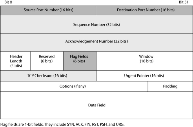
EXHIBIT 5.14 Transmission Control Protocol (TCP) Segment
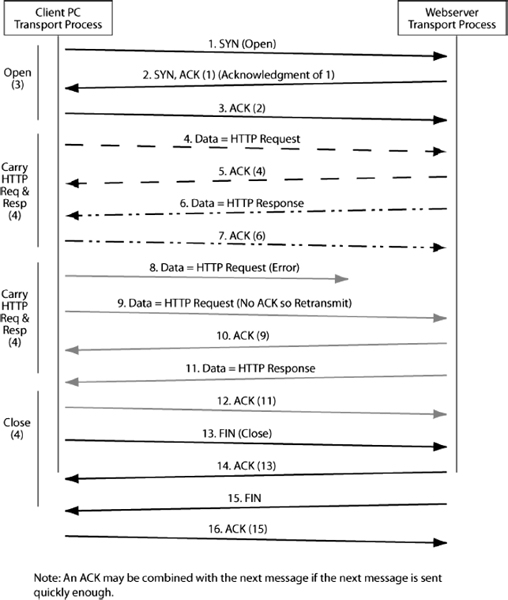
EXHIBIT 5.15 Messages in a TCP Session
Ending a conversation, in contrast, normally takes four messages. One side sends a FIN segment, which the other party acknowledges. Then the other party sends a FIN segment, which the other side acknowledges. After the first side sends the original FIN segment, it will not send any new information, but it will send acknowledgments for segments sent by the other party.
There is another way to end a session or even to reject opening one. At any point, either party can send a RST (reset) message. An RST message ends the conversation abruptly. There is not even an acknowledgment. It is like hanging up in a telephone conversation.
Attackers often preface an attack by attempting to identify the IP addresses of running hosts—much like thieves casing a neighborhood. One way to do this is to send TCP SYN segments to hosts. If hosts reject the SYN segment, they often send back an RST message. As noted earlier, TCP segments are carried in the data fields of IP packets. The source IP address in the packet delivering the TCP RST segment will be that of the internal host. Whenever the attacker receives an RST segment, this verifies the existence of a working host at that packet's IP address. Firewalls often stop RST segments from leaving a site to prevent them from reaching the attacker.
5.6.2 Reliability.
In addition to being connectionless or connection-oriented, protocols are either reliable or unreliable. An unreliable protocol does not detect and correct errors. Some unreliable protocols do not even check for errors. Others check for errors but simply discard a message if they find that it contains an error.
TCP is a reliable protocol. It actually corrects errors. The TCP checksum field is calculated using values from other fields. The sender places the result of its calculation in the checksum field. The receiver redoes the calculation and compares it with the transmitted value. If the receiving transport layer process finds that a message is correct (the values are the same), it sends an acknowledgment message. However, if the receiver detects an error in the TCP segment it receives (the values are different), it discards the segment and does nothing else.
How does a receiver know that there is an error in the message? The sender computes a value based on the other bits in the TCP segment (not just the header). The receiver redoes the calculation. If the two values match, the receiver sends an acknowledgment. If they do not match, the receiver merely drops the segment and does not send an acknowledgment.
If the segment arrives correctly, the original sender receives an acknowledgment. However, if the segment never arrives or is discarded because of damage, no reply is sent. If the original sender does not receive an acknowledgment in a specified period of time, it will resend the original segment. It will even use the original sequence number.
5.6.3 Flag Fields.
Flag field is a general name for a 1-bit field that is logical (true or false). To say that a flag field is set means that its value is 1. To say that a flag field is not set means that its value is 0.
The TCP header contains a number of flag fields. One of these is SYN. To request a connection opening, the sender sets the SYN bit. The other sends a SYN/ACK segment, in which both the SYN and ACK bits are set. Other commonly used flags are FIN, RST, URG, and PSH.
The URG flag indicates the presence of urgent data that should be handled before earlier data octets. The urgent pointer field indicates the location of the urgent data.
If an application message is large, TCP will divide the application message into multiple TCP segments and send the segments individually. To help the receiving TCP process, the sending transport process may set the PSH (push) bit in the application message's last segment. This tells the receiving transport process to push the data up to the application program immediately without buffering and delays.
5.6.4 Octets and Sequence Number.
The sequence number field value allows the receiver to put arriving TCP segments in order even if the packets carrying them arrive out of order (including when a segment is retransmitted). Sequence numbers are also used in acknowledgments, albeit indirectly. In TCP transmission, every octet that is sent, from the very first, is counted. This octet counting is used to select each segment's sequence number.
- For the first segment, a random initial sequence number (ISN) is placed in the sequence number field.
- If the segment contains data, the number of the first octet contained in the data filed is used as the segment's sequence number.
- For a purely supervisory message that carries no data, such as an ACK, SYN, SYN/ACK, FIN, or RST segment, the sequence number is increased by 1 over the previous message.
One dangerous attack is TCP session hijacking, in which an attacker takes over the role of one side. This allows the hijacker to read messages and send false messages to the other side. To accomplish session hijacking, the attacker must be able to predict sequence numbers because if a segment arrives with an inappropriate sequence number, the receiver will reject it. TCP session hijacking is likely to be successful only if the initial sequence number is predictable. Few operating systems today pick initial sequence numbers in a predictable way, but predicable sequence numbers were common in earlier operating systems, some of which are still in use.
5.6.5 Acknowledgment Numbers.
When a receiver sends an acknowledgment, it sets the ACK bit. It also puts a value in the acknowledgment number field to indicate which segment is being acknowledged. This process is needed because the sender sends many segments and because acknowledgments may be delayed.
You might think that the acknowledgment number would be the sequence number of the segment being acknowledged. Instead, it is the number of the last octet in the data field plus 1. In other words, the acknowledgment number gives the octet number of the first octet in the next segment to be sent. This seems a bit odd, but it makes certain calculations easier for the receiver.
5.6.6 Window Field.
Flow control limits the rate at which a side sends TCP segments. The TCP window field allows one to limit how many more octets the other side may send before getting another acknowledgment. The process is somewhat complex and has no known security implications at the time of this writing. In acknowledgments, the ACK bit is set, and both the acknowledgment and window size fields are filled in.
5.6.7 Options.
Like the IPv4 header, the TCP header can have options. However, while IP options are rare and cause for suspicion, TCP uses options extensively. One common option, often sent with the initial SYN or SYN/ACK segment, is the maximum segment size (MSS) option. This gives the other side a limit on the maximum size of TCP segment data fields (not on segment sizes as a whole). The presence of TCP options, then, is not suspicious by itself.
5.6.8 Port Numbers.
We have now looked at most fields in the TCP header. However, we have skipped the first two fields—the source and destination port number fields—in order to save them for the last.
5.6.8.1 Port Numbers on Servers.
Port number fields mean different things for clients and servers. For a server, it represents a specific application running on that server, as Exhibit 5.16 shows. Most servers are multitasking computers, which means that they can run multiple applications at the same time. Each application is specified by a different port number.
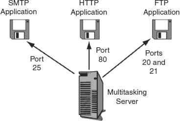
EXHIBIT 5.16 Multitasking Server Host and Port Numbers
For instance, on a server, a Web server application program may run on TCP Port 80. Incoming TCP segments that have 80 as their destination port number are passed to the Web server application. Actually, TCP Port 80 is the well-known port for Web server programs, meaning that it is the usual port number for the application. Although Web servers can be given other TCP port numbers, this makes it impossible for users to establish connections unless they know or can guess the nonstandard TCP port number.
The TCP port range from 0 to 1023 is reserved for the well-known port numbers of major applications, such as HTTP and e-mail. For instance, Simple Mail Transfer Protocol (SMTP) mail server programs usually are run on TCP Port 25, while File Transfer Protocol (FTP) requires two well-known port numbers—TCP Port 21 for supervisory control and TCP Port 20 for the actual transfer of files.
5.6.8.2 Port Numbers on Clients.
Client hosts use TCP port numbers differently. Whenever a client connects to an application program on a server, it generates a random ephemeral port number that it uses only for that connection. On Windows machines, the ephemeral TCP port numbers range from 1024 to 4999.
The Microsoft port number range for ephemeral port numbers may differ from the official IETF range, with values of 5000–65534. The use of nonstandard ephemeral port numbers by Windows and some other operating systems causes problems for firewall filtering.
5.6.8.3 Sockets.
Exhibit 5.17 shows that the goal of internetworking is to deliver application messages from one application on one machine to another application on another machine. On each machine, there is a TCP port number that specifies the application (or connection) and an IP address to specify a computer. A socket is a combination of an IP address and a TCP port number. It is written as the IP address, a colon, and the TCP port number. A typical socket, then, would be something like 128.171.17.13:80.
Attackers often do socket spoofing—both IP address spoofing and port spoofing. For instance, in TCP session hijacking, if the attacker wishes to take over the identity of a client, it must know both the client's IP address and ephemeral port number. Of course, these fields are transmitted in the clear (without encryption) in TCP, so an attacker with a sniffer that captures and reads traffic flowing between the client and server can easily obtain this information.
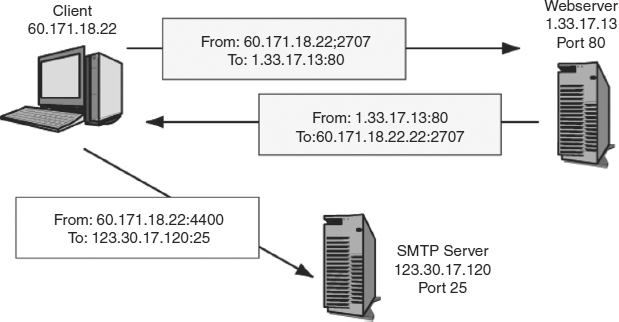
EXHIBIT 5.17 Sockets
5.6.9 TCP Security.
Like IP, TCP was created without security. However, while IPsec has made IP secure, the IETF has not created a comparable way to secure TCP. One reason for this is IPsec's ability to secure all transport layer traffic transparently, without modification to transport layer protocols. The IETF has made IPsec the centerpiece of its security protections and a single method to handle upper-layer security. Communicating partners that want TCP security should implement IPsec.
However, few TCP sessions are protected by IPsec. Consequently, some pairs of users employ an option in TCP, which adds an electronic signature to each TCP session. This signature proves the identity of the sender. This option, described in RFC 2385, requires the two parties to share a secret value. This option is awkward because it provides no way to share keys automatically, and it does not provide encryption or other protections. The option is used primarily in the Border Gateway Protocol (BGP). BGP is used to exchange routing information between administrative systems—say a corporate system and an internet service provider. BGP always uses one-to-one connections, the communicating parties usually know each other quite well, and the two parties have long-term relationships, which makes key exchange less burdensome and risky. Outside of BGP, however, the RFC 2385 electronic signature option does not appear to be used significantly. Even in BGP, it is widely seen as very weak security.
5.7 USER DATAGRAM PROTOCOL.
As noted earlier, TCP is a protocol that makes up for the limitations of IP. TCP adds error correction, the sequencing of IP packets, flow control, and other functionality that we have not discussed.
Not all applications need the reliable service offered by TCP. For instance, in voice over IP, there is no time to wait for the retransmission of lost or damaged packets carrying voice. In turn, the simple network management protocol (SNMP), which is used for network management communications, sends so many messages back and forth that the added traffic of connection-opening packets, acknowledgments, and other TCP supervisory segments could overload the network. Consequently, voice over IP, SNMP, and many other applications do not use TCP at the transport layer.
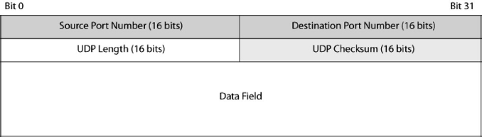
EXHIBIT 5.18 User Datagram Protocol (UDP)
Instead, they use the User Datagram Protocol (UDP). This protocol is connectionless and unreliable. Each UDP message (called a UDP datagram) is sent on its own. There are no openings, closings, or acknowledgments.
As a consequence of the simplicity of UDP's operation, the UDP datagram's organization is also very simple, as Exhibit 5.18 illustrates. There are no sequence numbers, acknowledgment numbers, flag fields, or most of the other fields found in TCP.
There are source and destination port numbers, a UDP header length to allow variable-length UDP datagrams, and a UDP checksum. If the receiver detects an error using the checksum, it simply discards the message. There is no retransmission.
The fact that both TCP and UDP use port numbers means that whenever you refer to port numbers for well-known applications, you also need to refer to whether the port numbers are TCP or UDP port numbers. This is why the well-known port number for Web servers is TCP port 80.
TCP's sequence numbers make TCP session hijacking very difficult. The receiver will discard messages with the wrong sequence numbers even if the source and destination sockets are correct. UDP lacks this protection, making UDP a somewhat more dangerous protocol than TCP.
Like TCP, UDP has no inherent security. Companies that wish to secure their UDP communication must use IPsec.
5.8 TCP/IP SUPERVISORY STANDARDS.
So far, we have looked at standards that deliver a stream of packets across an internet and that perhaps check for errors and provide other assurances. However, the TCP/IP architecture also includes a number of supervisory protocols that keep the Internet functioning.
5.8.1 Internet Control Message Protocol (ICMP).
The first supervisory protocol on the Internet was the Internet Control Message Protocol (ICMP). As Exhibit 5.19 shows, ICMP messages are delivered in the data fields of IP packets.
The best-known pair of ICMP message types is the ICMP echo message and the echo reply message. Suppose that a host sends an ICMP echo message to an IP address. If a host is active at that address, it may send back an ICMP echo reply message. This process is often called pinging because the most popular program for sending ICMP echo message is called Ping. The echo message is a very important tool for network management. If the network manager suspects a problem, he or she will ping a wide range of host addresses to see which of them are reachable. The pattern of responses can reveal where problems exist within a network.
Attackers also love to ping a wide range of host IP addresses. This can give them a list of hosts that are reachable for attacks. Another popular network management and attack tool is traceroute (or tracert on Windows PCs). Traceroute is similar to ping, but traceroute also lists the routers that lie between the sending host and the host that is the target of the traceroute command. This allows an attacker to map the network. Border firewalls often drop echo reply messages leaving the firm to the outside.
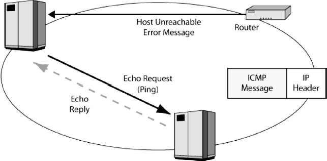
EXHIBIT 5.19 Internet Control Message Protocol (ICMP)
Many ICMP messages are error messages. For instance, if a router cannot deliver the packet, it may send back an ICMP error message to the source host. This error message will provide as much information as possible about the type of error that occurred.
If an attacker cannot ping destination hosts because a firewall stops them, attackers often send IP packets that are malformed and so will be rejected. The ICMP error message is delivered in an IP packet, and the source IP address in this packet will reveal the IP address of the sending router. By analyzing error messages, the attacker can learn how routers are organized in a network. This information can be very useful to attackers.
5.8.2 Domain Name System (DNS).
To send a packet to another host, a source host must place the destination host's IP address in the destination address field of the packets. Often, however, the user merely types the host name of the destination host, for instance, cnn.com.
Unfortunately, host names are only nicknames. If the user types a host name, the computer must learn the corresponding IP address. As Exhibit 5.20 shows, the host wishing to send a packet to a target host sends a Domain Name System (DNS) request message to the DNS server. This message contains the host name of the target host. The DNS response message sends back the target host's IP address. To give an analogy, if you know someone's name, you must look up their telephone number in a telephone directory if you want to call them. In DNS, the human name corresponds to the host name, the telephone number corresponds to the IP address, and the DNS server corresponds to the telephone directory.
DNS is critical to the Internet's operation. Unfortunately, DNS is vulnerable to several attacks. For example, in DNS cache poisoning, an attacker replaces the IP address of a host name with another IP address. After cache poisoning, a legitimate user who contacts a DNS server to look up the host name will be given the false IP address, sending the user to the attacker's chosen site. Denial-of-service attacks are also too easy to accomplish. RFC 3833 lists a number of DNS security issues.1
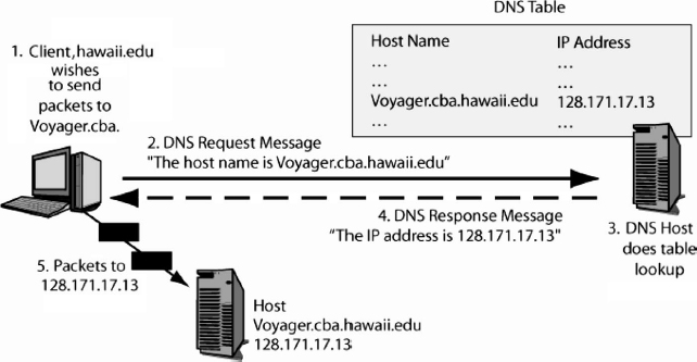
EXHIBIT 5.20 Domain Name System (DNS) Server
Several attempts to strengthen DNS security have been developed, under the general banner of Domain Name System Security Extensions (DNSSEC), especially RFC 25352. However, both the original DNSSEC specifications and the newer DNSSEC bis specifications (RFCs 4033-40353) have proven to be insufficient. Developing a security standard that is sufficiently backwardly compatible for Internet-scale implementation has proven to be extremely difficult.
If the DNS server does not know the host name, it contacts another DNS server. The DNS system contains many DNS servers organized in a hierarchy. At the top of the hierarchy are 13 DNS root servers. Below these are DNS servers for top-level domains, such as .com, .edu, .ie, .uk, .nl, and .ca. Each top-level domain has two or more top-level DNS servers for their domain. Second-level domain names are given to organizations (e.g., Hawaii.edu and Microsoft.com). Organizations are required to maintain DNS servers for computers within their domain.
If attackers could bring down the 13 root servers, they could paralyze the Internet. Widespread paralysis would not occur immediately, but in a few days, the Internet would begin experiencing serious outages.
5.8.3 Dynamic Host Configuration Protocol (DHCP).
Server hosts are given static (permanent) IP addresses. Client PCs, however, are given dynamic (temporary) IP addresses whenever they use the Internet. The Dynamic Host Configuration Protocol (DHCP) standard that we saw earlier in the chapter makes this possible. A DHCP server has a database of available IP addresses. When a client requests an IP address, the DHCP server picks one from the database and sends it to the client. The next time the client uses the Internet, the DHCP server may give it a different IP address.
The fact that clients may receive different IP addresses each time they get on the Internet causes problems for peer-to-peer (P2P) applications. A presence server or some other mechanism must be used to find the other party's IP address. A lack of accepted standards for presence (including presence security) is a serious issue now that P2P applications are widespread. In fact, most security considerations in P2P presence servers have been used in P2P piracy applications, with an eye toward avoiding discovery by legitimate authorities.
5.8.4 Dynamic Routing Protocols.
How do routers on the Internet learn what to do with packets addressed to various IP addresses? The answer is that they frequently talk to one another, exchanging information about the organization of the Internet. These exchanges must occur frequently because the structure of the Internet changes frequently as routers are added or dropped. Protocols for exchanging organization information are called dynamic routing protocols. There are many dynamic routing protocols, including the Routing Information Protocol (RIP), Open Shortest Path First (OSPF), the Border Gateway Protocol (BGP), and Cisco Systems' proprietary Enhanced Interior Gateway Routing Protocol (EIGRP). Each is used under different circumstances. These protocols have widely different security features, and different versions of each protocol have different levels of functionality.
If an attacker can impersonate a router, he or she can send false dynamic routing protocol messages to other routers. These false messages could cause the routers to misdeliver their packets. The attacker could even cause packets to pass through the attacker's computer, in order to read their contents.
The protocols just listed have widely different security features, and different versions of each protocol have different levels of security functionality.
5.8.5 Simple Network Management Protocol (SNMP).
Networks often have many elements—routers, switches, and host computers. Managing dozens, hundreds, or thousands of devices can be nearly impossible. To make management easier, the IETF developed the Simple Network Management Protocol (SNMP). As Exhibit 5.21 shows, the manager program can send SNMP messages to managed devices to determine their conditions. The manager program can even send configuration messages that can change the ways in which remote devices operate. This allows the manager to fix many problems remotely.
Many firms disable remote configuration because of the damage that attackers could do with it. They could simply turn off all ports on switches and routers, or they could do more subtle damage.
5.9 APPLICATION STANDARDS.
Most applications have their own application layer standards. In fact, given the large number of applications in the world, there are literally hundreds of application layer standards.
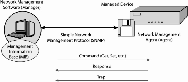
EXHIBIT 5.21 Simple Network Management Protocol (SNMP)
As corporations get better at defending against attacks at lower layers, attackers have begun to focus their attention on application vulnerabilities. If an attacker can take over an application running with high privileges, he or she obtains these privileges. Many applications run at the highest privileges, and attackers that compromise them own the box.
5.9.1 HTTP and HTML.
Many applications have two types of standards. One is a transport standard to transfer application layer messages between applications on different machines. For the World Wide Web, this is the Hypertext Transfer Protocol (HTTP). The other is a standard for document structure. The main document structure standard for the WWW is the Hypertext Markup Language (HTML).
Netscape, which created the first widely used browser, also created a security standard to protect HTTP communication. This was Secure Sockets Layer (SSL). Later, the Internet Engineering Task Force took over SSL and changed the name of the standard to Transport Layer Security (TLS).
5.9.2 E-Mail.
Popular transfer standards for email are the Simple Mail Transfer Protocol (SMTP), Post Office Protocol (POP), and Internet Message Access Protocol (IMAP) for downloading e-mail to a client from a mailbox on a server. Popular document body standards include RFC 2822 (for all-text messages), HTML, and Multipurpose Internet Mail Extensions (MIME). S/MIME (Secure MIME) adds public-key encryption (see Chapter 7) to MIME and is defined in RFCs 2634, 3850, and 3851.
An obvious security issue in e-mail is content filtering. Viruses, spam, phishing messages, and other undesirable content should be filtered out before they reach users and can do damage. (For more information on spam and other low-technology attacks, see Chapter 20 in this Handbook; for malware and spam countermeasures see Chapters 26, 27, 31, and 41.)
Another security issue in e-mail is securing messages flowing from the sending client to the sender's mail server, to the receiver's mail server, and to the receiving client. Fortunately, there are security standards for part or all of the message flows, including SSL/TLS and S/MIME among others. Unfortunately, the IETF has been unable to agree on a security standard.
When Web mail, which uses HTTP and HTML for e-mail communication, is used, then SSL/TLS can work between the sender and the sender's mail server and between the receiver's mail server and the receiver. Transmission between the e-mail servers is another issue. Of course, senders can send encrypted message bodies directly to receivers. However, this prevents filtering at firewalls. Users should be particularly careful about using Web mail via wireless connections. (See Chapters 32 and 33.)
5.9.3 Telnet, FTP, and SSH.
The two earliest applications on the Internet were the File Transfer Protocol (FTP) and Telnet. FTP provides bulk file transfers between hosts. Telnet allows a user to launch a command shell (user interface) on another computer. Neither of these standards has any security. Of particular concern is that both send passwords in the clear (without encryption) during login. The newer Secure SHell (SSH) standard can be used in place of both FTP and Telnet while providing high security.
5.9.4 Other Application Standards.
There are many other applications and therefore application standards. These include Voice over IP (VoIP; see Chapter 34 in this Handbook), peer-to-peer applications (P2P; see Chapter 35), and service-oriented architecture (SOA) and Web service applications (see Chapters 21, 30, and 31), among many others. Most applications have serious security issues. Application security has become perhaps the most complex aspect of network security (see Chapters 38, 39, and 40).
5.10 CONCLUDING REMARKS.
It is impossible to understand information security without a strong knowledge of networking. This chapter is designed to give you a working overview of networking. It is likely to be sufficient if you run into basic networking questions while reading other chapters. However, to work in security, you will need a much stronger knowledge of networking. The books and other resources cited in Section 5.11 are a good start in that direction.
5.11 FURTHER READING
Comer, D. E. Internetworking with TCP/IP Vol.1: Principles, Protocols, and Architecture, 5th ed. Upper Saddle River, NJ: Prentice-Hall, 2005.
Ferrero, A. The Eternal Ethernet. Boston: Addison-Wesley, 1999.
FitzGerald, J. and A. Dennis. Business Data Communications and Networking, 9th ed. Upper Saddle River, NJ: Prentice-Hall, 2006.
Freedman, A. Computer Desktop Encyclopedia. Point Pleasant, PA: Computer Language Company, 2008. Available on CD-ROM and online from www.computerlanguage.com.
Kurose, J. F., and K. W. Ross. Computer Networking: A Top-Down Approach, 4th ed. Boston: Addison-Wesley, 2007.
Muller, N. J. Wireless Data Networking. Boston: Artech House Publishers, 1995.
Panko, R. R. Business Data Networks and Telecommunications, 6th ed. Upper Saddle River, NJ: Prentice-Hall, 2006.
Panko, R. R. Corporate Computer and Network Security. Upper Saddle River, NJ: Prentice-Hall, 2004.
Price, R. Fundamentals of Wireless Networking. Boston: Career Education, 2006.
Rackley, S. Wireless Networking Technology: From Principles to Successful Implementation. Boston: Newnes, 2007.
Spurgeon, C. Ethernet: The Definitive Guide. Sebastopol, CA: O'Reilly, 2000.
Stevens, W. R. TCP/IP Illustrated, Volume 1 : The Protocols. Boston: Addison-Wesley, 1994.