Adding and Creating PSpice Models
Abstract
PSpice models can be created and edited in the PSpice Model Editor. When users edit a PSpice part from Capture, a copy of the PSpice model is created in a library file, which will have the same name as the project. This is so that the original PSpice model does not get modified. The copied library is written to the project file and can be seen as one of the configured PSpice libraries in the Project Manager. For PSpice simulation, a Capture part needs to have four specific properties attached. These are the implementation: name of the model; implementation path: left blank as model is searched for in the configured libraries in the simulation profile; implementation type: PSpice Model; and PSpice template: provides the Capture part interface to the model or subcircuit. The Model Editor is used to view text model definitions and to display graphical model characteristics and model parameters. The Model Editor has the facility to make a copy of an existing PSpice model from an existing library. The Model Import Wizard, File > Import Wizard [Capture], allows one to view and select, or replace Capture parts (symbols) for the models in a library one at a time. The Model Editor is useful for displaying the characteristic curves for models, especially if the PSpice model has been downloaded from a vendor's website. There is an encryption facility in the Model Editor that allows one to encrypt PSpice models or libraries such that the models can be used for simulation but the model definitions cannot be viewed.
Keywords
PSpice models; Transistor; Simulation; Bipolar; Voltage; Diode; characteristic curves
PSpice models can be created and edited in the PSpice Model Editor, which can be started in standalone mode from the Start menu, PSpice > Simulation Accessories > Model Editor, or by highlighting a PSpice part in the schematic in Capture, rmb > Edit PSpice Model. When you edit a PSpice part from Capture, a copy of the PSpice model is created in a library file, which will have the same name as the project, i.e. < project name >.lib. This is so that the original PSpice model does not get modified. The copied library is written to the project file and can be seen as one of the Configured PSpice libraries in the Project Manager. Whenever you create a new Capture part for a PSpice model, you need to reference the library in which the model can be found by providing the path to the library file in the simulation profile under the Configuration Files > Category > Library.
16.1 Capture Properties for a PSpice Part
For PSpice simulation, a Capture part needs to have four specific properties attached. These are the:
• Implementation: name of the model
• Implementation Path: left blank as model is searched for in the configured libraries in the simulation profile
• Implementation Type: PSpice Model
• PSpiceTemplate: provides the Capture part interface to the model or subcircuit
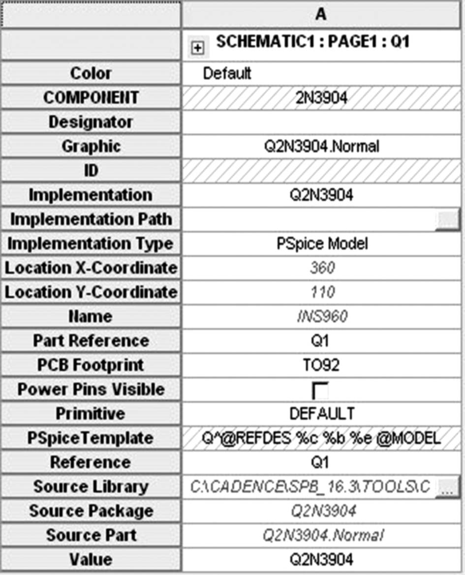
The above properties are automatically added when a Capture part is created either in Capture or in the Model Editor. Fig. 16.1 shows the attached properties for a Q2N3904 transistor.
The PSpiceTemplate is defined as:
where the first character Q defines a bipolar transistor. Other common device types are shown in Table 16.1. A complete table of device types can be found in the PSpice A/D Reference Guide.
Table 16.1
PSpice implementation definitions
| Character | Device type | Pin order |
| R | Resistor | 1,2 |
| C | Capacitor | 1,2 |
| L | Inductor | 1,2 |
| D | Diode | Anode, cathode |
| Q | Transistor | Collector, base, emitter |
| M | MOSFET | Drain, gate, source, bulk |
| Z | IGBT | Collector, gate, emitter |
| I | Current source | + ve node, − ve node |
| V | Voltage source | + ve node, − ve node |
| X | Subcircuit | Node 1, node 2, …node n |
The ˆ is used by the netlister to define the hierarchical path to the device. The ˆ is effectively replaced by the hierarchical path to the device. For example, the netlist in Fig. 16.2 is that of a hierarchical design consisting of a Top level design containing a Bottom hierarchical block. At the bottom level, there are two resistors R1 and R2, their hierarchical paths being defined by R_Bottom_R1 and R_Bottom_R2. There is also a resistor at the top level, R1.

@REFDES is the reference designator such as Q1, R2, etc. The % defines the pin names, the order of which is defined in Table 16.1 and the @MODEL references the PSpice model name.
16.2 PSpice Model Definition
The basic definition for a PSpice model is given by:
.MODEL < model name > < model type >
+ ([< parameter name > = < value >
The model name must start with one of the PSpice device characters as shown in Table 16.1 and can be up to eight characters long. The model type is specific to the model; for example an NPN type is specific only to a bipolar transistor. Table 16.2 shows the associated model types for the PSpice models.
Table 16.2
PSpice model types
| Model | Device type | Device |
| Qname | NPN | NPN bipolar |
| PNP | PNP bipolar | |
| LPNP | Lateral PNP | |
| Dname | D | Diode |
| Cname | CAP | Capacitor |
| Kname | CORE | Non-linear magnetic core |
| Lname | IND | Inductor |
| Mname | NMOS | N-channel MOSFET |
| PMOS | ||
| Jname | NJF | N-channel JFET |
| PJF | P-channel JFET | |
| Rname | RES | Resistor |
| Tname | TRN | Transmission line |
| Bname | GASFET | N-channel GAsFET |
| Zname | IGBT | N-channel IGBT |
| Nname | DINPUT | Digital input device |
| Oname | DOUTPUT | Digital output device |
| Wname | ISWITCH | Current-controlled switch |
| Uname | UADC | Multibit ADC |
| UDAC | Multibit DAC | |
| UDLY | Digital delay line | |
| UEFF | Edge-triggered flip-flop | |
| UGATE | Standard gate | |
| UIO | Digital I/O model | |
| UTGATE | Tristate gate | |
| Sname | VSWITCH | Voltage-controlled switch |
For example, the model definition for a Q2N3904 transistor is given by:

The model name, Q2N3904, starts with a letter Q to signify that this is a bipolar transistor model. The model type is that of NPN and the parameter list is enclosed in { } brackets. The comment lines start with an asterisk, ∗, and gives information such as the semiconductor vendor, date of creation and the printed circuit board (PCB) footprint.
Most devices are defined using the basic model definition. However, the complete PSpice model definition is given by:
.MODEL < model name > [AKO: < reference model name >]
+ < model type >
+ ([< parameter name > = < value > [tolerance specification]]⁎
+ [T_MEASURED =< value >] [[T_ABS =< value >] or
+ [T_REL_GLOBAL =< value >] or [T_REL_LOCAL =< value >]])
A Kind of (AKO) is used when you want to create a model based upon another model (referenced) but change some of the model parameters. For example, if you want to create a 2N3904 transistor model which has a minimum BF of 75 but want to keep the other model parameters the same, then the model definition would be:
.model Q2N3904_minBF AKO:Q2N3904 NPN (BF = 75)
In this way you can build up a family of transistors based on the original transistor but with different parameters.
In the model definition there are three parameters that relate to the temperature at which the model parameter values were calculated or measured:
T_ABS
T_REL_GLOBAL or T_REL_LOCAL
T_MEASURED is the temperature at which model parameters were measured or derived. Default is 27°C and, if set, this overrides TNOM.
T_ABS sets the absolute device temperature. No matter what the circuit temperature, the device temperature will be equal to T_ABS.
T_REL_GLOBAL is used to provide a temperature offset from the circuit temperature. The device temperature will be equal to the difference between the circuit temperature and T_REL_GLOBAL.
T_REL_GLOBAL is useful if you have a transistor that is going to be operating at a higher temperature than other transistors. For example, if you have a 2N3904 transistor that is going to be located near a heat source which is running at 5°C higher than ambient temperature, then you would add T_REL_GLOBAL = 5°C to the end of the parameter list as shown below:
.model Q2N3904 NPN(Is = 6.734f Xti = 3 Eg = 1.11 Vaf = 74.03 Bf = 416.4 Ne = 1.259
+ Ise = 6.734f Ikf = 66.78m Xtb = 1.5 Br = .7371 Nc = 2 Isc = 0 Ikr = 0 Rc = 1
+ Cjc = 3.638p Mjc = .3085 Vjc = .75 Fc = .5 Cje = 4.493p Mje = .2593 Vje = .75
+ Tr = 239.5n Tf = 301.2p Itf = .4 Vtf = 4 Xtf = 2 Rb = 10 T_REL_GLOBAL = 5)
∗ National pid = 23 case = TO92
∗ 88-09-08 bam creation
∗$
So when you run a temperature analysis at − 55°C, 27°C and 125°C, the Q2N3904 will be simulated at − 50°C, 32°C and 130°C.
16.3 Subcircuits
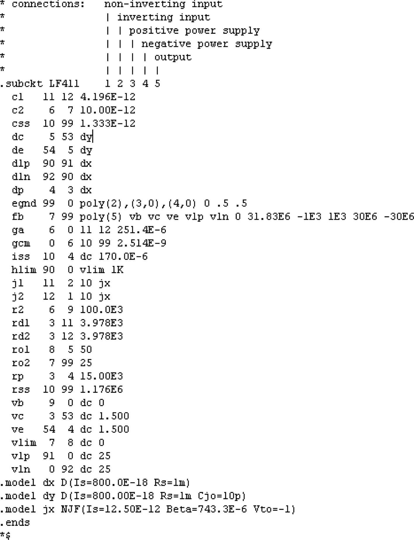
PSpice devices can also be represented as a network of components, which is the usual case for operational amplifiers (opamps) and voltage regulators. These devices are classed as subcircuits and the first letter in the PSpiceTemplate is an X. The PSpiceTemplate for the LF411 opamp is shown below:
Xˆ@REFDES %+ %- %V + %V- %OUT @MODEL
The order of the pins must match the PSpice subcircuit definition for the LF411 as shown below:
16.4 Model Editor
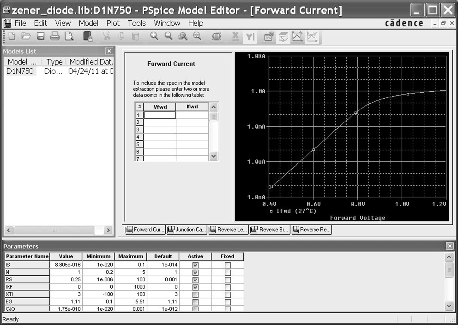
The Model Editor is used to view text model definitions and to display graphical model characteristics and model parameters. Fig. 16.3 shows the forward current versus voltage curve for a diode. When the Model Editor first loads the PSpice library, the model text description is shown. To see the graphical model characteristics, select View > Extract Model. Fig. 16.3 also shows a table in which data from a manufacturer's datasheet can be entered such that a new model can be created based upon the manufacturer's empirical data.
New models can be created by first selecting File > New, to create a library file, then Model > New, to create a model (Fig. 16.4).
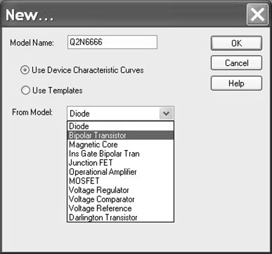
There are 11 device models to choose from, and the option for Use Device Characteristic Curves, which represents the normal PSpice models, and Use Template, which relates to parameterized models. The Use Templates is for parameterized models, which are used in the PSpice Advanced Analysis software and are not covered in this text.
Once a model has been created, a Capture part can automatically be generated. The first character of the model name and the model type defined in Table 16.2 determine which type of Capture part to generate. Before you generate a Capture part, you need to make sure that the correct schematic editor is selected. In Tools > Options > Schematic Editor, select Capture (Fig. 16.5).

As mentioned previously, the part generated will be determined by the first character in the model name and the model type. If the part to be generated is one of the standard PSpice devices, then you can use File > Export to Capture Part Library. As shown in Fig. 16.6, you select the libraries in which to save the PSpice model (.lib) and associated Capture part (.olb). A message window will appear, reporting whether the translation has been successful.

16.4.1 Copying an Existing PSpice Model
The Model Editor has the facility to make a copy of an existing PSpice model from an existing library. Selecting Model > Copy From, the Copy Model window shown in Fig. 16.7 is displayed. You browse to the Source Library and select the model from the displayed model list and enter the New Model name.

16.4.2 Model Import Wizard
The Model Import Wizard, File > Import Wizard [Capture], allows you to view and select or replace Capture parts (symbols) for the models in a library one at a time. You browse to the input model library and specify the destination symbol library as shown in Fig. 16.8. The good news is that the Model Import Wizard will display opamp symbols for opamps created in the Model Editor rather than rectangular boxes. The other good news is that you can browse for an existing Capture symbol to associate with the model.

In Fig. 16.9 an international rectifier MOSFET has been copied from the IRF.lib library, modified and saved as myIRF540. You also have the option to view the model text, which is useful if you need to check the pin names.

As no symbol exists for the MOS device yet, clicking on Associate Symbol will allow you to browse to a suitable library which contains a symbol for an NMOS transistor (Fig. 16.10).
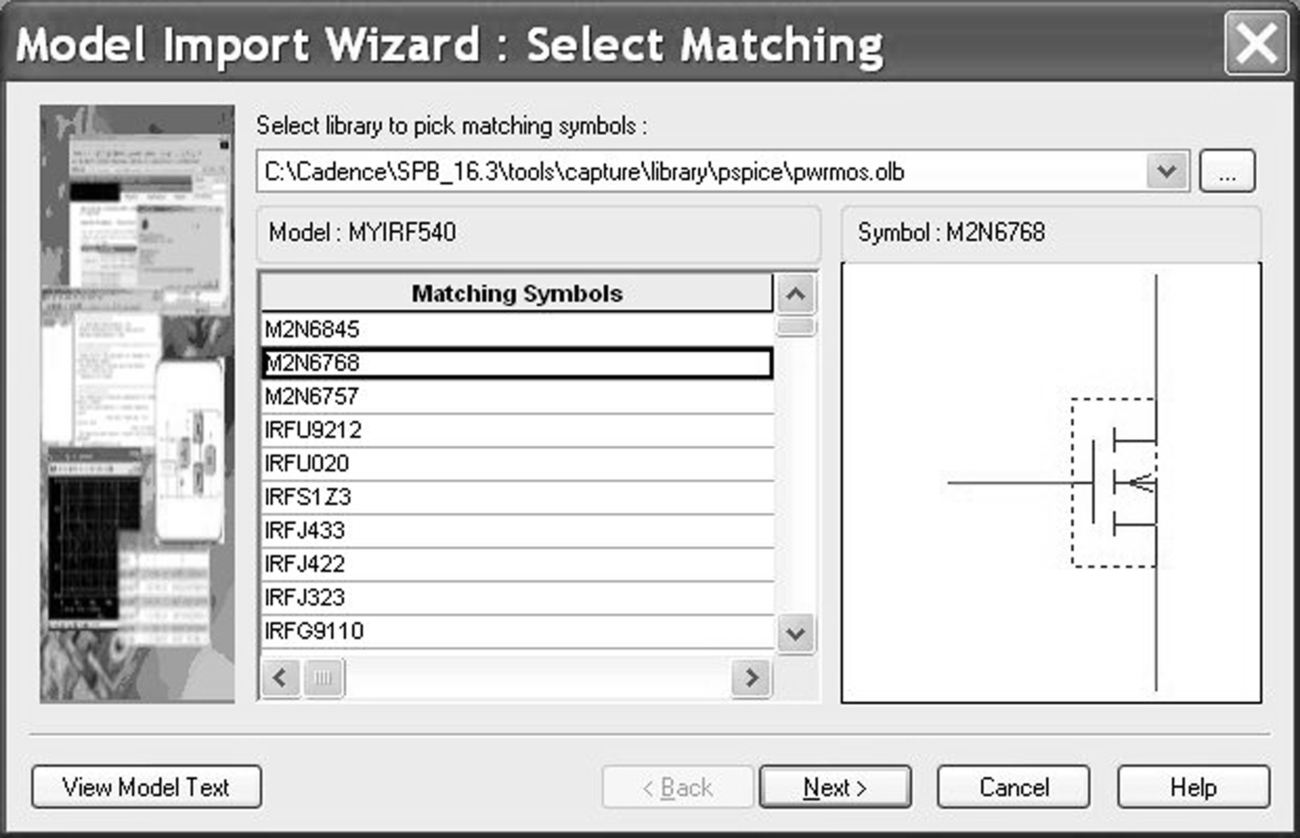
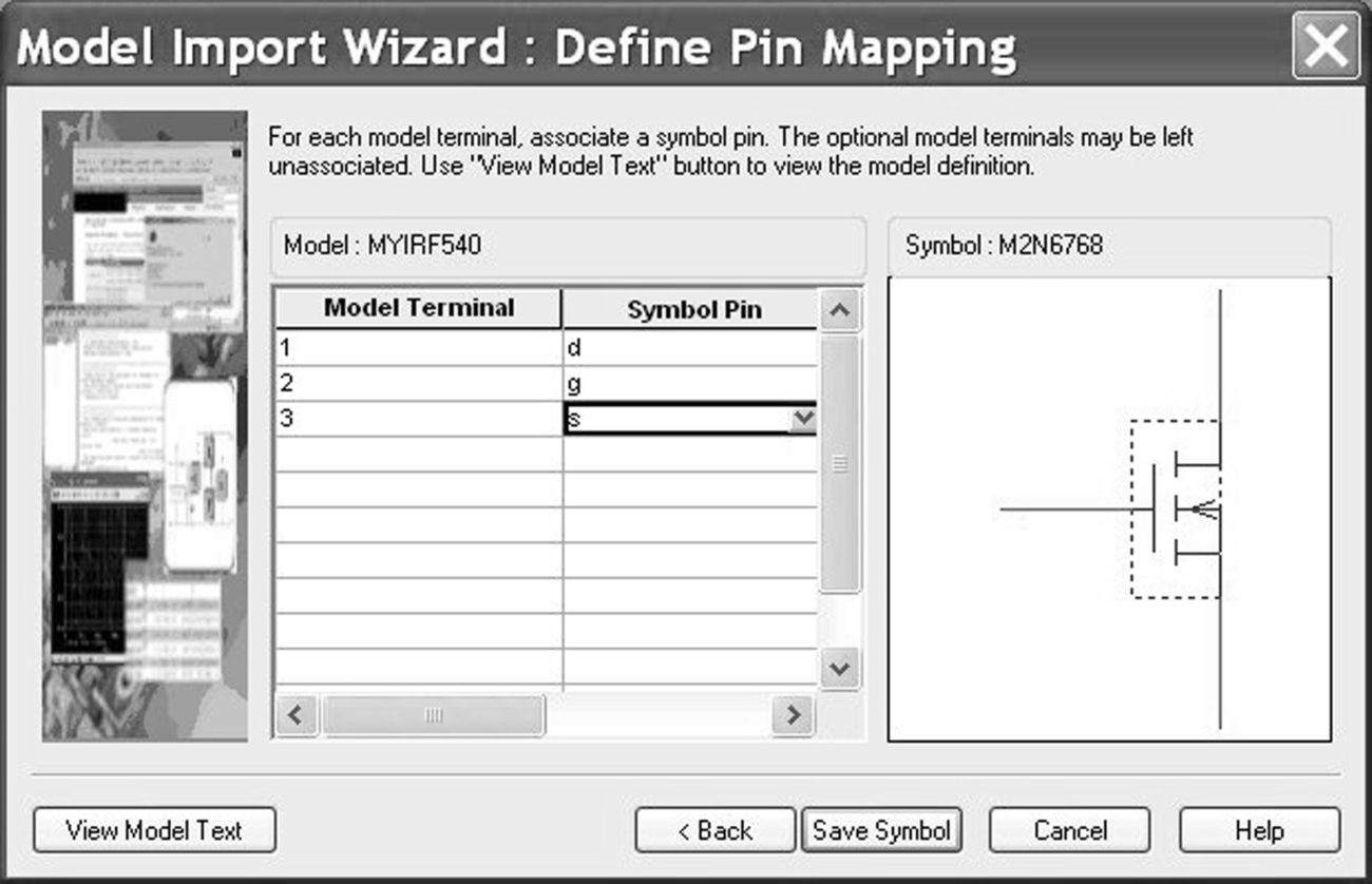
In this example, the Capture symbol for an NMOS symbol was found in the pwrmos.olb library (Fig. 16.10). However, you now have to associate the model terminals (1, 2, 3) with the Capture symbol pins (d, g, s) (Fig. 16.11). All the symbol pin names will be listed.
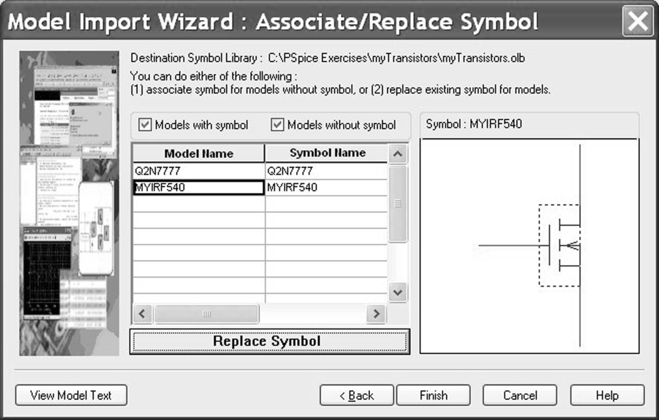
When you select Save Symbol in Fig. 16.11, the models listed in the PSpice myTransistors.lib library file are shown (Fig. 16.12). Note that as all models have an associated capture symbol, the option to Replace Symbol is now shown. If there is no associated symbol, the option Associate Symbol is shown.
An example of using the Model Import Wizard can be found in Chapter 21, Exercise 2.
16.4.3 Downloading Models From a Vendor Website
The Model Editor is useful for displaying the characteristic curves for models, especially if the PSpice model has been downloaded from a vendor's website. By default, the Model Editor ignores the first line in a PSpice model file, so make sure the .model statement starts on the second line. Comment lines can be added to the model by starting the line with an asterisk, ∗, so it is always a good idea to add information regarding the model to the file, for example:
⁎ Q2N7777 transistor downloaded from semiconductor website 23.4.2011
A Capture part can also be generated in Capture from a PSpice model. In the Project Manager highlight the design file (.dsn) and select Tools > Generate Part to open the Generate Part window (Fig. 16.13). Select Netlist/source file type to PSpice Model Library and browse to the PSpice model in Netlist/source file. Then in Implementation name select the model name from the file. If you have downloaded a library of models, then all the individual model names will be available.

16.4.4 Encryption
There is an encryption facility in the Model Editor that allows you to encrypt PSpice models or libraries such that the models can be used for simulation but the model definitions cannot be viewed. To encrypt a model library, select File > Encrypt Library and in the Library Encryption window (Fig. 16.14) browse to the library to be encrypted and the folder where the library will be saved to.

If you only want to encrypt part of the library, i.e. two of the PSpice library models, then add the following text to the beginning and end of the model definitions:
$CDNENCSTART beginning of model text
$CDNENCFINISH end of model text
If Partial Encryption is not checked, then the Show Interfaces option allows you to encrypt the model text definition but still display the model interfaces, i.e. the model connecting pins such as emitter, base and collector for a bipolar transistor.
16.4.5 IBIS Translator
IBIS 1.1 models are supported in 16.5 whereas 16.6 supports IBIS models up to version 5.0.
In 16.6, IBIS and Cadence proprietary Device Model Language (DML) files can be translated into PSpice library files in the Model Editor. The translated IBIS I/O buffers are defined as macromodels.
IBIS (Input Output Buffer Information Specific) models are mainly used to analyse the transmission of digital high speed signals between ICs where the transmitted medium, usually copper traces, are modelled as transmission lines. The input and output buffers of ICs are characterised by tables of measured Voltage/Current and Voltage/Time data to provide a representation of I/O buffer behaviour without disclosing any proprietary information regarding the internal implementation of the I/O buffers. IBIS models based on these V/I and V/T tables can be used to analyse the Signal Integrity of the transmission of data by predicting the circuit response to mismatched impedance lines, crosstalk from adjacent transmission lines, overshoot, undershoot, ground bounce and simultaneous switching of digital high speed signals.
IBIS models provide a relatively accurate simulation model as they take into account structures for ESD protection and inherent parasitics associated with die bonding to the IC package pins. Compared to standard SPICE models, IBIS simulations run faster and do not suffer from non-convergence issues.
DML files are used by the existing suite of high speed simulation Cadence software tools for high speed analysis.
The IBIS translator is in the Model Editor and can be accessed from the top tool bar.
The IBIS translator is not available in the demo Lite CD.
16.5 Exercises
Exercise 1
The breakdown voltage for a zener diode will be modified using the Model Editor.
1. Create a project called zener_diode and draw the circuit in Fig. 16.15. The 4V7 zener diode can be found in either the eval library or the diode library.

2. Create a PSpice > New Simulation Profile and select the Analysis type to DC sweep. Create a simulation profile for a DC sweep for V1 from 1 to 10 V in steps of 0.1 V (Fig. 16.16) to confirm the 4.7 V zener diode breakdown voltage. It does not matter if V1 has a voltage of 0 V as shown in the schematic, as a DC sweep is being performed.

3. Select the diode and rmb > Edit PSpice Model to open the Model Editor. Note the library name at the top of the Model Editor, zener_diode.lib (Fig. 16.17).
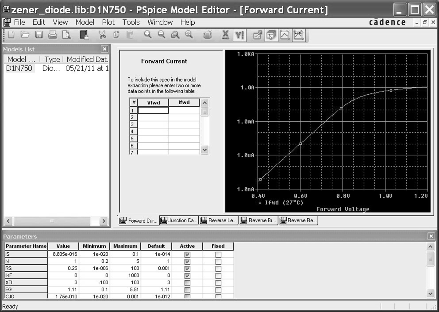
4. From the top toolbar, select View > Extract Model. In the first PSpice Model Editor window, click on Yes, then click on OK in the next window regarding parameters. The Model Editor will display the forward current characteristic for the diode as shown in Fig. 16.17.
5. Under the displayed curve, click on each of the five tabs to view the diode model characteristics. When you select a curve, the Parameter window (Fig. 16.18) displays an Active check against each parameter that is associated with the displayed characteristic curve. Note the diode characteristic for the Reverse Breakdown curve and the active parameters.

6. In the Parameters section at the bottom of the Model Editor, scroll down and locate the diode breakdown parameter, BV. Change the value from 4.7 to 8.2 V and click on the Fixed box (Fig. 16.19). Select the Reverse Breakdown tab under the curve, which should have changed to 8.2 V.

7. Save the library file, File > Save and close the Model Editor.
8. Edit the Simulation Profile. Select Configuration Files > Library and note that the zener_diode.lib has been added to the profile. The attached design icon  indicates that the file is local only to the design (Fig. 16.20). The world icon
  , indicates that the file is global and can be seen by all designs. The nom.lib contains all the PSpice library files and hence is global to all designs.
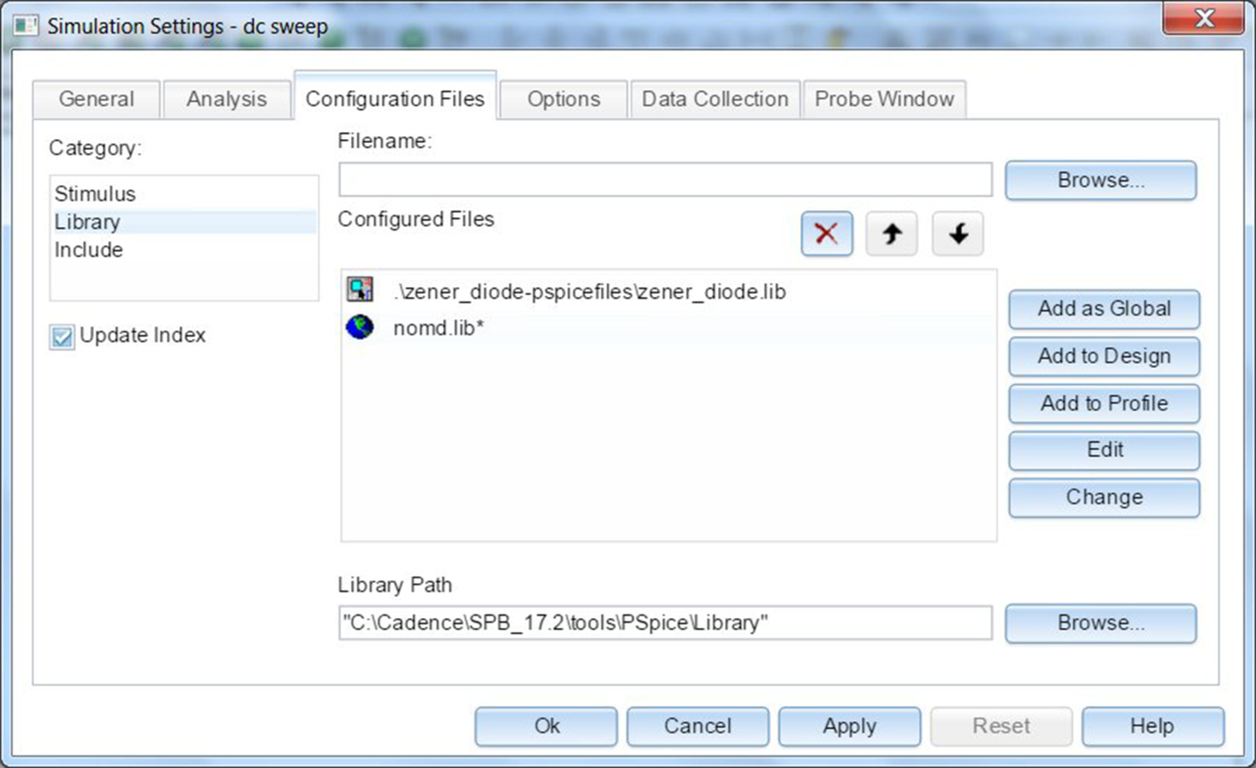
9. Select the zener_diode.lib file and click on Edit. The Model Editor will open up. Select the D1N750 in the Models List and the diode model parameter will appear as before. This enables model library files to be quickly viewed. Close the Model Editor and the simulation profile.
10. Rerun the simulation and confirm that the diode breakdown voltage is now 8.2 V.
Exercise 2
Whenever you create a new PSpice model and Capture part it is recommended that you create a new directory for your model. Do not install the new libraries in the Capture or PSpice folders. If a new OrCAD release is installed, then the PSpice and Capture libraries will be reinstalled and so any new models created will be lost.
For this exercise we will assume that a PSpice model for a transistor has been downloaded from a semiconductor's website. In order to recreate this scenario we will copy an existing transistor model from the bipolar.lib library to a new file, myTransistors.lib.
1. Using a text editor such as WordPad or Notepad, browse to the installed PSpice libraries, < install path > Orcad 16.3ToolsPSpiceLibrary, and select the bipolar.lib or eval.lib PSpice library. Make sure you select Files of type to All Files.
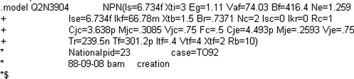
2. In the library file, scroll down and select the Q2N3904 model definition as shown below (use Control F to find the Q2N3904):
3. Select the model text and copy and paste it into a new text file. Do not use rich text format (RTF) if using WordPad.
4. Edit the transistor model name to Q2N7777 and add a comment line to the first line 1 as shown below:

5. Save the file as myTransistors.lib in a folder called myTransistors. Make sure the file is saved as text and not RTF, otherwise control characters will be added to the model text.
6. Create a new PSpice project called myTransistors.
7. In the Project Manager make sure the myTransistors.dsn file is highlighted and select Tools > Generate Part. In the Generate Part window (Fig. 16.21) select:
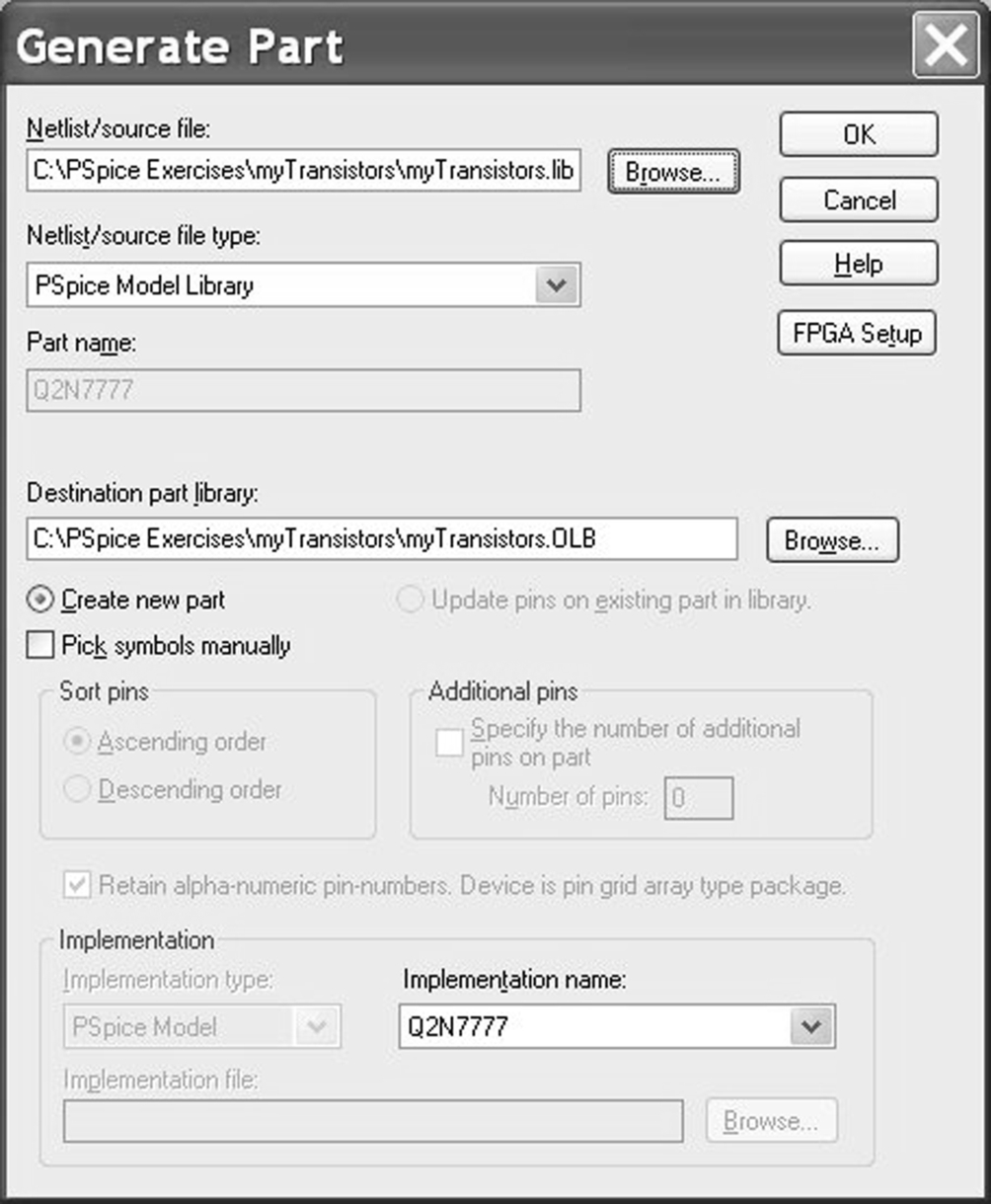
In Netlist/source file: type: select PSpice Model Library
In Netlist/source file: browse to the myTransistors.lib file.
In Destination part library: browse to the same folder where myTransistors.lib is.
In Implementation name: there will only be one entry Q2N7777.
Click on OK.
8. The myTransistors.olb Capture library will be created and added to the library folder in the Project Manager (Fig. 16.22). Expand the library to see the Q2N7777 part.
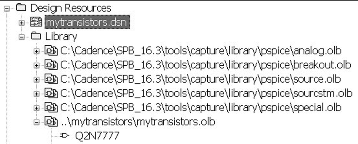
9. Open the schematic page and select Place > Part or press P on the keyboard (Fig. 16.23). The library myTransistors has automatically been added to the libraries and the Part List contains the transistor graphical symbol for an NPN transistor (Fig. 16.23).
Also, the PSpice icon appears, indicating that the transistor has a PSpice model attached  . You now need to make the myTransistors.lib file available for simulation in the Simulation Profile.

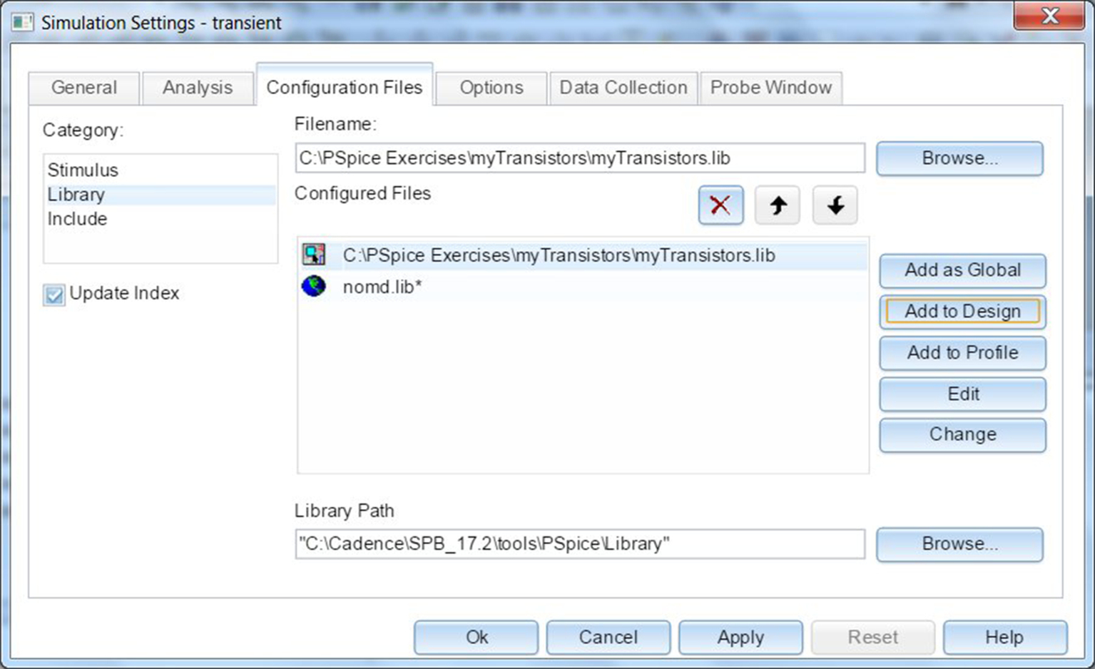
10. Create a new simulation profile, PSpice > New Simulation Profile. Under the Configurations Files tab, select Category > Library and browse to the folder where myTransistors.lib is. As mentioned in Exercise 1 Step 8, you can add the library files Global to the design, local to the design or to the Profile. In this exercise, add the file as Global (Fig. 16.24) and click on OK. The transistor is ready to be simulated and the myTransistors.lib library will be available for every new design.
Exercise 3
In Exercise 2, the model definition for the Q2N7777 has a Q for the first character in the model name, so this is recognized as a transistor and has an NPN as the model type. Hence, an NPN transistor symbol was generated. If the model name starts with an X for a subcircuit, a rectangular box is drawn which can then be edited in Capture using the Part Editor. You highlight the part in the library, rmb > Edit Part. Many of the power MOSFET models, for example, are defined as subcircuits.
However, in the Model Editor, the Model Import Wizard can be used to select an existing Capture graphic symbol for the model rather than having to edit the graphics in the Part Editor.
1. Open the Model Editor from the Start menu: All Programs > Cadence (or OrCAD) > PSpice > Simulation Accessories > Model Editor.
2. Select File > Open and browse to the myTransistors.lib library file. Click on Q2N7777 in the Models List and the model text will be displayed. Note that the first line which you added is not displayed.
3. Select View > Extract model and click on Yes in the Model Editor window. There will be eight characteristic curves for the transistor model.
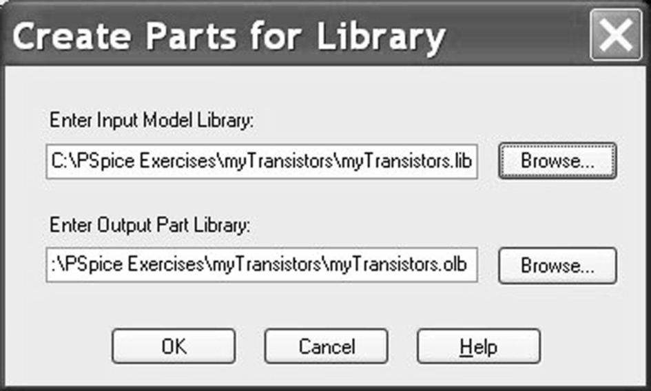
4. Select File > Export to Capture Part Library. If the Capture option is not available, select Tools > Options and select Capture as the Schematic Editor (see Fig. 16.5).
In the Create parts for Library window, the output library folder will show the same location as the PSpice library file, as shown in Fig. 16.25. Click on OK and if a window appears asking to save the library, click on Yes. The translator window will appear and hopefully report no errors.
Exercise 4
You can also copy PSpice models from existing models in the Model Editor.
1. In the Model Editor, open the bipolar.lib library from the PSpice library folder.
2. Select Model > Copy From and in the Copy Model window enter Q2N3906X in New Model, select Q2N3906 from the library list and click on OK (Fig. 16.26).

Exercise 5
New models can be created in the Model Editor. In the demo CD you can only create new diode models in the Model Editor. Models can be created using data from device characteristic curves from manufacturer's data sheets or alternatively, parameterized models can be created for use in PSpice Advanced Analysis (see Chapter 23). The Use Templates is for parameterized models that are used in the PSpice Advanced Analysis software, see Chapter 23.
The Use Templates is for parameterized models, which are used in the PSpice Advanced Analysis software and are not covered in this text. For this exercise, select Use Device Characteristic Curves.
1. In the Model Editor, select File > New.
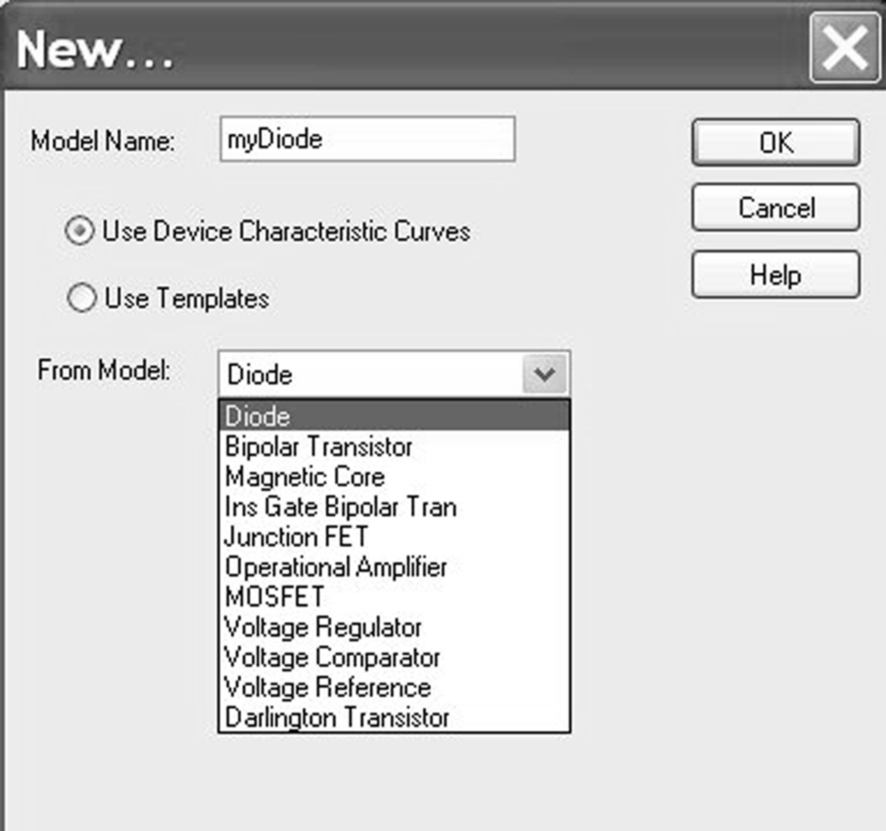
2. Select Model > New and enter myDiode as the model name and select, Use Device Characteristic Curves (Fig. 16.27). Click on OK.
3. There are five characteristic curves for the diode model that can be displayed by clicking on the tabs at the bottom of the curves (see Fig. 16.28). You enter the data for each diode characteristic and then select, Tools > Extract Parameters. The extracted model parameters are displayed at the bottom of the Model Editor can be changed and the values fixed.

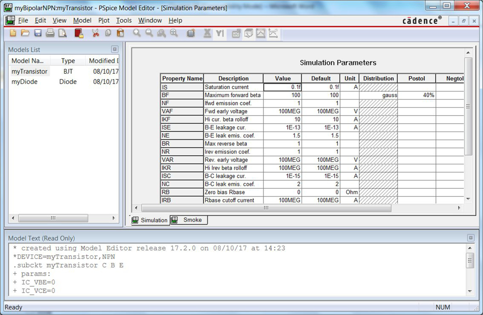
4. Create a new model called myTransistor or myDiode2 if you are using the Lite version but this time, select the Use Templates option and select the Bipolar NPN type as shown in Fig. 16.29. Click on OK.

5. Fig. 16.30 shows the parameterized properties for the transistor. You can enter tolerance and distribution spreads for each parameter as shown. These parameters are used in PSpice Advanced Analysis (Chapter 23).