
As we previously discussed in Chapter 14, data is a very important part of form development and all too often it is overlooked or written off at development time. We've all encountered the mentality of "one thing at a time"; we'll consider implementing that in the next phase; we can't do everything at once, anything will be better than what we had.
If we design the form, only to expect the form recipient to mail or fax back a printed copy of that information, we have solved only a minute piece of the overall form collection problem, the readability of the returned data. What about the need to enter that data into an electronic system, or sharing that data with interested parties in our organization?
Mailing or faxing requires the form recipient to take additional steps that rely on them to follow through with the process. What if they lose the fax number, or don't have access to a fax machine? The Postal Service does a wonderful job of delivering mail as long as it is legible, has a valid address, and proper postage. These are just a few of the items that can cause a delay in data collection. Even worse, we may never receive the data. Capturing data electronically is the real value in creating fillable forms.
In this chapter we focus on working with XML form data in a Designer form. After we discuss how XML is structured, we explore creating data connections in Designer to streamline testing and extracting data.
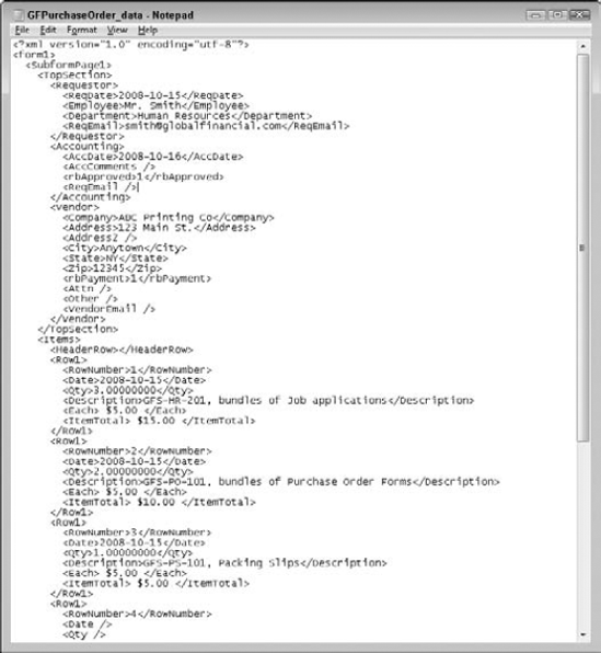
Extensible Markup Language (XML) is an open-source industry standard document markup language designed to structure, store, and transport data. Data in the XML file is stored as plain text. This allows for software and hardware independent data storage. The data is stored in the XML file with self-descriptive tags. The tags are not predetermined by the XML specification; they are defined by the author of the XML file. An XML data file can store any data where the structure can be represented as a tree. A sample XML file from our Purchase Order form developed in Chapter 28 is shown in Figure 31.1.
You can use many different applications to create a sample XML file. When and how the XML file is created depends on your preferred workflow. Some possible options include:
An existing data source. Use one of these options when a database, spreadsheet, or other data file already exists and the Designer form needs to collect or present data that is stored in those existing fields:
Use the data source. An existing data source can be used to create the XML file and then connected to a form to create the necessary data bindings. Most database programs allow you to export the data set as an XML file, and many include the option for exporting the schema as well.
Use XSLT. If the form and the data source have already been created, changing either can be difficult. It may be best to use an Extensible Stylesheet Language Transformation file to transform the form data to match the data source. The XSLT can be applied to either the form or the data source.
No existing data source. Use one of these options when there is not an existing data file designed to store the information:
Create a new XML file. Using an XML editor, the data structure can be designed before the form or the data source is created.
Create the XML from the Form. Use the existing Designer form, or create a new form, and use it to generate the sample XML file.
Create the data source. Continue with the preceding options in the existing data source section.
In situations where a data source is managed by another department, it is best to coordinate the sharing of data before the form design takes place. This can save a large amount of design time by allowing us to generate the data bindings while building the form. Do not underestimate the importance of collecting the data into a useful format. Explore the documentation of the programs you use for information on exporting to XML.
Keep in mind that the XML the form generates for efficient field use in Designer is not equivalent to an XML file that would be efficient for a spreadsheet or a database. How you decide to store the data for easy retrieval and reporting depends on many factors: your comfort level with the computer programs available, the complexity of the data, and the intended use of the collected data.
In static forms where no items repeat, the data can be stored easily in a flat file. Think of a flat file as a row in a spreadsheet where each column contains a unique heading, and a single row contains the information the form contained. Using the form to generate the sample XML followed by importing that information into a spreadsheet works well for flat files.
Note
For instructions on how to use the form to generate a sample XML file, see Chapter 28.
Taking our sample XML file we can simply open it in a spreadsheet program such as Microsoft Excel and continue to append additional data through the import external data process. We also can use the distribute features of Acrobat to collect the form data into a response file that can be exported to a spreadsheet after all of the responses have been collected. The exported data also can be imported into a database program.
Note
For information on distributing forms and collecting responses, see Chapters 14 and 30.
When dynamic forms use repeating sections, a database that can handle relational data is better suited to store the data. Trying to store relational data in a spreadsheet program causes some common problems: repeating data in multiple rows to store the relational components as separate lines; and repeating columns to store data in a single row. A relational database program can store the information in multiple related tables to eliminate storing repeating data and optimize data retrieval.
When using a relational database, we recommend that the database be constructed first, and the XML schema be created from the database and used in the form development.
XML is stored in a structured tree format. The following list introduces many of the XML terms we use in this chapter:
Attribute. An attribute is part of an element that provides additional descriptive information regarding that element. Attributes appear inside the element tag, and the attribute value must always be quoted.
Note
Attributes can be better expressed as a nested child element in many cases. Elements have more functionality than attributes. Attributes cannot contain multiple values, cannot describe structure, are not expandable, and are more difficult to manipulate with code.
Child. An element contained within another element is considered a child element. This is also known as nesting elements.
Document prolog. The document prolog resides outside of the root element and is usually the first thing in the XML file. The prolog contains up to three pieces of information:
<?xml version="1.0" encoding="utf-8"?>
The XML declaration. The declaration states the version of XML in use in the document.
The character encoding. If this is omitted, it is assumed that Unicode Transformation Format (UTF-8) or UTF-16 is in use.
Document Type Declaration. The Document Type Declaration may be included in the document prolog and contains a link to the Document Type Definition (DTD) file if one is in use. A Document Type Definition provides the documentation regarding the elements and attributes contained in the XML file, including their relationships. DTD are not used very frequently because XML Schema Definition files are the current preferred method for describing XML files.
Element. The elements make up the majority of the XML file. Elements include the starting tag of the element, the closing tag of the element, and everything in between. This means an element may contain attributes, other elements, or text. In the following example element, the element is all of the text including the tags:
<form> This is the content inside the form tags. </form>
Nesting. The process of placing one element inside another creates a nested element. The outer element is known as the parent and the inner element is known as the child.
Parent. The outer element of a nested pair of elements is considered the parent. This is also known as nesting elements.
Root element. Only one root element is allowed, and is alternatively called the document element. All other elements are nested inside the root element.
Tag. Tags come in pairs. The first tag is the starting tag and defines the beginning of the element. The second tag is the closing tag and indicates the end of the element. The tags include the characters that indicate the start or end of an element, but not the element content itself. An example element appears as follows:
<message> These contents are not tags. </message>
The tags contain the word "message" and are always enclosed in < and > symbols
Valid. An XML file is valid when it is both well formed and conforms to some semantic rules that are user-defined. The XML is validated against the DTD or the XML Schema associated with the file.
Well-formed. An XML file is well formed when it conforms to all of the XML syntax rules.
The XML syntax rules are:
XML documents must have a root element. Only one root element is allowed and all other elements must be nested inside the root element.
All XML elements must have a closing tag. Missing tags cause malformed XML to be unreadable. The following data fails because of the missing </Employee> tag.
</Form>
<ReqDate>2008-10-15</ReqDate>
<Employee>Mr. Smith
<Department>Human Resources</Department> <ReqEmail>smith@
      globalfinancial.com</ReqEmail>
</Form>
XML elements must be properly nested. Elements must be closed in the opposite order from the order in which they are started. The following data from our purchase order file is improperly nested and fails because the employee tag was not properly closed before the department data was introduced:
</Form>
<ReqDate>2008-10-15</ReqDate>
<Employee>Mr. Smith
<Department>Human Resources</Department></Employee>
<ReqEmail>[email protected]</ReqEmail>
</Form>
XML Schema Definition. An XML Schema Definition (XSD) is an XML-based alternative to a DTD file. The XSD describes the structure of the XML document. XML Schemas are more powerful than DTDs; they support data types and name spaces.
XML tags are case sensitive. You must open and close a tag using the same case. A good example is:
<Department>Human Resources</Department>
A bad example is indicated by the lowercase letter d in the closing tag that does not match the opening tag case:
<Department>Human Resources</department>
XML attribute values must be quoted. If you choose to use attributes in your XML file the values must be enclosed in quotes. In the following variation of our purchase order information, the date of the request has become an attribute of the form tag:
<Form ReqDate="2008-10-15">
<Employee>Mr. Smith</Employee>
<Department>Human Resources</Department>
<ReqEmail>[email protected]</ReqEmail>
</Form>
Entity references are required. Only the following five entity references are built into the XML specification:
&. Used for the ampersand symbol (&).
<. Used for the less than symbol (<).
>. Used for the greater than symbol (>).
". Used for a quotation mark symbol (").
&apos. Used for the apostrophe symbol (').
Some additional notes regarding XML files:
Comments. In XML, comments are enclosed between the following symbols:
<!-- and -->. An example of a comment is the following:
<!-- Form revision reviewed 6/1/08 with team. -->
White space. White space is preserved in XML files. Extra spaces appear just as they are stored in the XML.
Empty elements. A special shorthand is allowed for empty elements in XML files that do not break the rule that all elements must have a closing tag. The following two lines of code are equivalent:
<ReqEmail></ReqEmail>
<ReqEmail/>
Becoming more familiar with these terms makes working with XML data files easier. You can find additional information regarding XML and XML Schema files on the W3Schools Web site at: www.w3schools.com.
When you choose to work with the XML data file directly we recommend using another program. The XML source tab in Designer is for the form design, not the sample XML data. Many editors exist for this purpose. Because XML is raw text, if you are comfortable editing on your own any text editing tool will work including Notepad, Wordpad, and Microsoft Word.
Programs that are designed specifically for working with XML give you additional tools such as color-coordinating objects, statement completion, and graphical representation of the XML data. Two of the free XML editing programs are:
XML Notepad 2007. This is a free Microsoft product. Our Purchase Order XML file exported from the PDF form is shown in Figure 31.2 as opened in XML Notepad 2007.
Note
For more information on using XML Notepad, see Chapter 27.
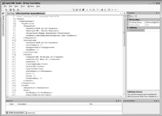
Liquid XML Studio 2008. This product is from Liquid-Technologies and is available in a free community edition or a purchased edition. The same purchase order XML file is shown open in Liquid XML in Figure 31.3.
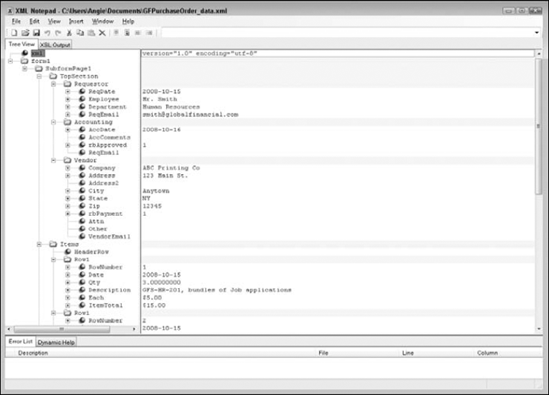
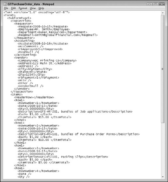
As you can see from Figures 31.2 and 31.3 the XML editors vary greatly in appearance. Another view of the same XML data appears in Figure 31.4 when opened in Windows Notepad.
All of the available tools, whether purchased or free, offer editing capabilities for modifying the structure of the XML by adding elements, attributes, and data values. How you edit the XML varies in each product, as do the features they offer. Some of the XML editors offer Schema editing tools.
Choosing an XML editor is a personal preference. Take the time to find an XML editor you are comfortable with to modify your data files. Most of the purchase products also offer trial downloads to test the software before purchasing.
Don't overlook the tools you already own. If you purchased Acrobat Pro or Pro Extended as part of an Adobe Creative Suite bundle, you may already own Adobe Dreamweaver, which is a great XML editor as well.
Regardless of which data type you decide to work with, you need to create the data connection in the Designer form to ensure the fields bind correctly to the data source. All of the data connection types have pros and cons. In this section we explore each type and explain why you may want to use or avoid a particular data connection for your form.
Creating a new Data Connection ties the form to the available data source. It does not explicitly set any field bindings. Implicit binding can occur once the Data Connection is established. We cover field binding later in the "Setting Field Bindings" section of this chapter.
Note
For more information on data binding terms, see Chapter 25. For specifics on creating field bindings to a data connection see the section "Setting Field Bindings" later in this chapter.
Getting started with a new data connection begins the same way for all four connection types. You can create a new data connection in three ways:
File Menu. Select File

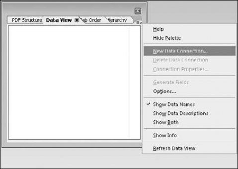
Right-click in the Data View palette. Open the Data View palette by selecting Window
The Data View palette Menu. Open the Data View palette by selecting Window
When you've opened the New Data Connection dialog box, the first decision is what type of data connection to make. A form may have more than one data connection established, but the form can use only one XML sample file or one XML schema file. We discuss the specifics of each of the connection types in the next section.
XML schema files are more powerful as a data connection in Designer than XML sample data files. The schema describes the elements in the XML data so that additional properties can be determined in the Designer form. A schema file that includes data types, field sizes, and occurrence information can set those properties for you in your form design.
Schema are imperative to working with the LiveCycle ES components in order to be able to use the built-in XPath formula windows. Without the schema all formulas must be manually created by typing the equivalent to branch of the XML tree each time you wish to use an element.
Note
For more information on the LiveCycle ES components, see Chapter 34.
Note
For the following steps we use the POSchema.xsd file from the Chapter 31 folder on the book's CD-ROM.
STEPS: Binding to an XML Schema
Open a form, or create a new one. We choose to start with a new form design.
Open the Data View palette. Select Window
Right-click in the Data View palette and select New Data Connection. Right-clicking in the Data View palette opens the context menu options where you can find the New Data Connection option.
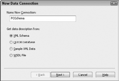
Give the Data Connection a name. We typed POSchema as our Data Connection name. This name does not have to be the same name as the file you are connecting to. It should be descriptive enough to indicate what the form is using as a data source. The Connection name cannot contain spaces, nor start with a number.
Select the XML Schema radio button. This sets the data connection type to be an XML Schema Definition (XSD). The dialog box should match Figure 31.6.
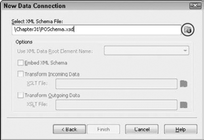
Browse for the XSD file. As shown in Figure 31.7, use the browse button to find the XSD file you wish to use.
If desired, select the Embed XML Schema option. This increases the file size, but adds extensive drill-down capabilities when writing XPath formulas in the LiveCycle ES components and reusing the data later
If desired, select the Transform options. When connecting a form to a data source that uses different XML elements, an Extensible Stylesheet Language Transformation (XSLT) can be used to convert the XML from one format to the other. An XSLT can be applied to the incoming data, the outgoing data, or both if needed.
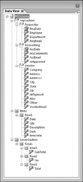
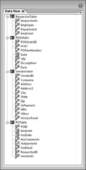
Select Finish to establish your data connection. Once the dialog box has closed, the Data View palette is populated with the Schema information as shown in Figure 31.8.
Once the data connection has been established, you can bind your schema file to the existing fields in the form even if they do not share the same name. Or, if you are starting from scratch with a new form the XML schema can be used to generate the form fields, including the data type and field size if specified in the schema.
If no XML schema is available, binding to an XML sample file is the next best option. A sample XML file allows you to bind fields on the form with fields in the sample XML file even if they don't have the same name. However, the sample XML file knows only the field names. It knows nothing about the data type, field size, or any attributes. If you use the sample XML file to create your form fields, all fields are text data types until you alter them.
Note
For the following steps we use the GFPurchaseOrder_data.xml file from the Chapter 31 folder on the book's CD-ROM.
STEPS: Binding to an XML Sample File
Open a form, or create a new one. We choose to start with a new form design.
Open the Data View palette. Select Window
Right-click in the Data View palette and select New Data Connection. Right-clicking in the Data View palette opens the context menu options where you can find the New Data Connection option.
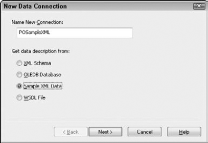
Give the Data Connection a name. We typed POSampleXML as our Data Connection name. This name does not need to match the name of the file you are connecting to. It should be descriptive enough to indicate what the form is using as a data source. The connection name cannot contain spaces, nor start with a number.
Select the Sample XML Data radio button. This sets the data connection type to be a sample XML file. The dialog box should match Figure 31.9.
Browse for the sample XML File. Use the browse button to find the XML file you wish to use.
If desired, select the Transform options needed. When connecting a form to a data source that uses different XML elements an Extensible Stylesheet Language Transformation (XSLT) can be used to convert the XML from one format to the other. A XSLT can be applied to the incoming data, the outgoing data, or both if needed.
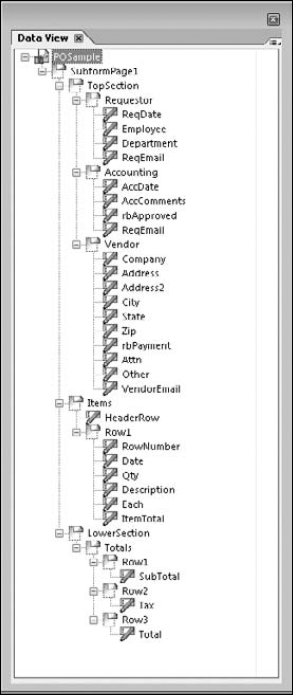
Select Finish to establish your data connection. Once the dialog box has closed, the Data View palette is populated with the sample XML information as shown in Figure 31.10.
Binding to a database is another connection option. Using a database tied directly to a form requires scripting to control when records can be inserted, updated, and deleted and to perform the record navigation capabilities for the records in the database. Without the necessary script, form recipients may be able to alter database records they should only be viewing.
A form can be connected to more than one database connection. OLEDB is the only database connection allowed with LiveCycle Designer ES. By using Microsoft OLEDB, an integration standard, for your ODBC drivers you can also access other databases by using a Data Source Name (DSN).
Security concerns in Acrobat specify that the client computer must have a DSN configured for each ODBC connection to function. External data connections are restricted in the free Adobe Reader unless the form has extended usage rights from LiveCycle Reader Extensions.
Warning
Binding directly to a database is restricted in the free Adobe Reader and requires that the form have extended usage rights from LiveCycle Reader Extensions.
The preferred method of binding data to a database is by using another process or product to control the processing of the form data. This may be done by LiveCycle Forms ES, a Web service, or other data solution provider. If you still wish to connect directly to the database you need to set up a Data Source Name (DSN) for each database connection on every machine that needs to connect to that file. On a Windows machine the settings can be found in the Administrative Tools of the Control Panel.
STEPS: Creating a Data Source Name (DSN) on Windows
Open the Control Panel. You can find this in the Start menu as a link for most Windows machines. It also can be opened from a Run command by typing control.exe and pressing Enter.
Open the Administrative Tools. The Administrative Tools are located in the System and Maintenance category when working in Category view. Or, Administrative Tools can be found alphabetically listed in the Classic view.
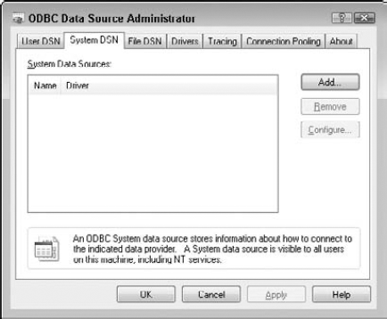
Open Data Sources (ODBC). This opens the ODBC Database Administrator.
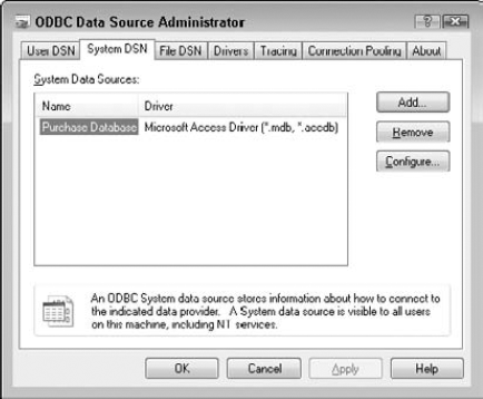
Select the System DSN tab. The DSN window appears showing any existing system Data Source Names, and allows you to create new Data Source Names as shown in Figure 31.11.
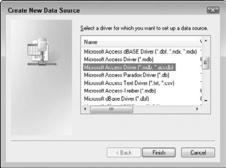
Select the Add button to create a new data source connection. Figure 31.12 shows the dialog box where the driver type of the data source is selected.
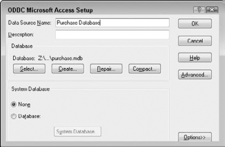
Select the appropriate driver type for the data source and select Finish. This opens the Connection window for the driver type selected. Figure 31.13 shows the Microsoft Access Setup window.
Type in a Data Source Name (required) and supply a description (optional). The data source name does not have to match the database name.
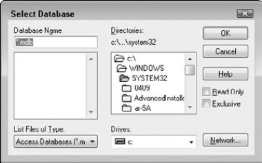
Use the Select button to browse for the database file. Figure 31.14 shows the Select Database dialog box used to browse for the data source.
Select the database and press OK. This returns you to the setup dialog box shown in Figure 31.14.
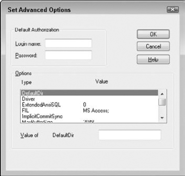
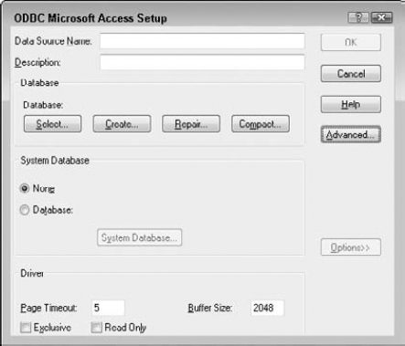
Set additional options as needed. If the database requires a password, you may supply it using the Advanced button as shown in Figure 31.15. It is also possible to set the database to open in Read Only mode or Exclusive Mode by expanding the options as shown in Figure 31.16.
Select OK to finish the Access setup window. The System DSN tab now shows the System Data Source Name you defined as shown in Figure 31.17.
Be sure to use the same settings on all of the computers that connect to the data source so as not to cause naming conflicts. Once the Data Source Name has been created on the form recipient's computer the Designer form can be configured to use the data source as long as the form recipient uses Acrobat (Standard, Pro, or Pro Extended) to complete the form, or if the form has been given extended usage rights by LiveCycle Reader Extensions to work in the free Adobe Reader.
Note
For the following steps we use the Purchase.mdb file from the Chapter31 folder on the book's CD-ROM.
STEPS: Binding to OLEDB
Open a form, or create a new one. We choose to start with a new form design.
Open the Data View palette. Select Window
Right-click in the Data View palette and select New Data Connection. Right-clicking in the Data View palette opens the context menu options where you can find the New Data Connection option.
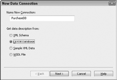
Give the Data Connection a name. We typed PurchaseDB as our Data Connection name. This name does not have to match the name of the file you are connecting to. It should be descriptive enough to indicate what the form is using as a data source. The Connection name cannot contain spaces, nor start with a number.
Select the OLEDB Data radio button. This sets the data connection type to be a database connection. The dialog box should match Figure 31.18.
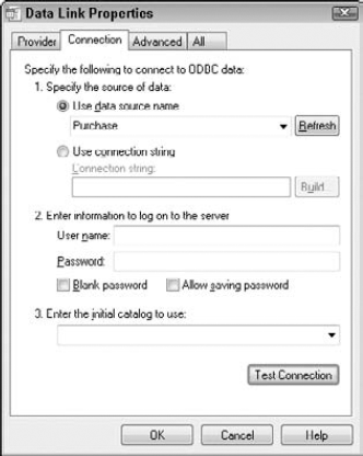
Select the Build Button. Use the Build button to find the database name you created in previous steps "Creating a Data Source Name (DSN) on Windows" in the Data Link Properties dialog box.
Select the Connection Tab of the Data Link Properties window.
Choose the DSN name from the drop-down list. The DSN name previously set up appears in the drop-down list. Figure 31.19 shows the Connection Tab with the DSN name selected.
Select the Test Connection Button. Verify your database connection is set up properly by testing the connection.
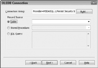
Select OK to return to the OLEDB connection window. Even though the connection string appears in the window, as shown in Figure 31.20, by connecting to the DSN, Acrobat is allowed to connect to the data source.
Select the Table, Stored Procedure or SQL Query you wish to use for your form and select Next. This entire process may be repeated as many times as needed to connect to all of the objects in the database you wish to use.
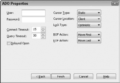
If the database requires authentication, enter the username and password or other options. Figure 31.21 shows the additional options available in the ADO Properties window.
Select Finish to create your data connection. Once the dialog box has closed the Data View palette is populated with the database information as shown in Figure 31.22.
Be very cautious when setting up OLEDB connections directly to a database without another buffer between the form and data in the database. It is very easy for the form recipient to add and remove data. We highly recommend that you utilize another tool such as the Adobe LiveCycle ES components to help manage the data between the form and the database.
A Web Service Definition Language (WSDL) file is an XML-based language for describing Web services. A program connecting to a Web service can read the WSDL to determine what functions are available on the server, and request an available service. A Designer form can have multiple WSDL connections. The Web services offered vary greatly in what they are and what they can do. Some examples include:
Conversions. Currency, temperature, units of measure, pressure, power, angles, languages, and more.
Look up Utilities. ZIP codes, weather, sunrise/sunset time, IP addresses, area codes, ISBN numbers, verify e-mail addresses, and verify mailing addresses, for example.
Graphics. Barcodes and Braille.
Communications. Text or fax messages.
Business. Mortgage rates, validate credit cards, gold and silver rates, validate bank routing information, stock quotes, and more.
Connecting a Designer form to a WSDL to perform these services is available if the form will be completed in Acrobat (Standard, Pro, or Pro Extended). WSDL calls are restricted in the free Adobe Reader program. Extended rights would be required from LiveCycle Reader Extensions for Reader to be able to utilize the Web services.
STEPS: Binding to an WSDL
Open a form, or create a new one. We choose to start with a new form design.
Open the Data View palette. Select Window
Right-click in the Data View palette and select New Data Connection. Right-clicking in the Data View palette opens the context menu options where you can find the New Data Connection option.
Give the Data Connection a name. We typed in CurrencyConvertor as our Data Connection name. This name does not have to match the name of the file you are connecting to. It should be descriptive enough to indicate what the form is using as a data source. The Connection name cannot contain spaces, nor start with a number.
Select the WSDL File radio button and choose next. This sets the data connection type to be Web Service Definition Language file.
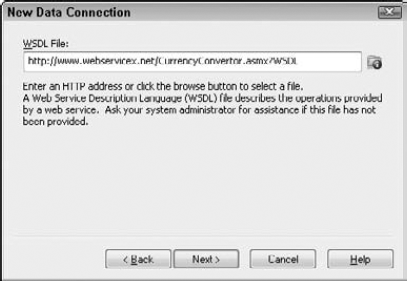
Type in the URL of the WSDL. If you are unsure of the URL it is recommended that you open a browser window and locate the WSDL file, then copy and paste the URL into the dialog box in Designer. Figure 31.23 shows the URL of a currency convertor used in our file.
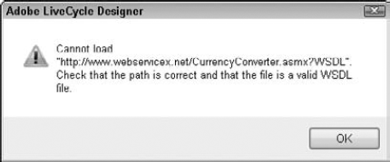
If the WSDL connection cannot be established the error shown in Figure 31.24 appears. Many different things can cause this error including mistyping the URL, the Web service is not currently available, no Internet connection is available, attempting with Adobe Reader or an unsupported version of Adobe Acrobat (prior to 7.05).
Select the Connection Properties. Once the WSDL has been successfully connected, a property window appears showing the available options. Normally a SOAP request or Post/Get request is what you find here as shown in Figure 31.25.
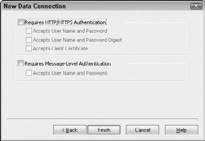
Specify any additional Connection properties as needed. Not all WSDL files allow public connections. If using a secure WSDL connection, you need to specify additional properties as shown in Figure 31.26.
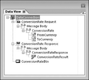
Select Finish to establish your data connection. Once the dialog box has closed, the Data View palette is populated with the WSDL services as shown in Figure 31.27.

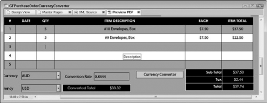
After you have created the WSDL connection you can integrate the available WSDL services with the rest of the form functionality. We decided to expand the Purchase Order by adding a currency convertor to the price. Use the Web service to take the vendor's currency format and convert it to our currency format. Use the returned currency conversion rate to adjust the total on the Purchase Order accordingly.
Tip
For a list of a number of WSDL services you can find on the Internet, visit www.xmethods.net.
Note
For the following steps we use the GFPurchaseOrder_Start.xdp file from the Chapter31 folder on the book's CD-ROM.
STEPS: Adding a Currency Convertor WSDL to the Purchase Order Form
Open a form. We'll open the GFPurchaseOrder_Start.xdp from the CD-ROM in Chapter 31.
Open the Data View palette. Select Window
Right-click in the Data View palette and select New Data Connection. Right-clicking in the Data View palette opens the context menu options where you can find the New Data Connection option.
Give the Data Connection a name. We typed CurrencyConvertor as our Data Connection name.
Select the WSDL File radio button and choose Next. This sets the data connection type to Web Service Definition Language file.
Type in the URL of the WSDL and choose next. We typed in:
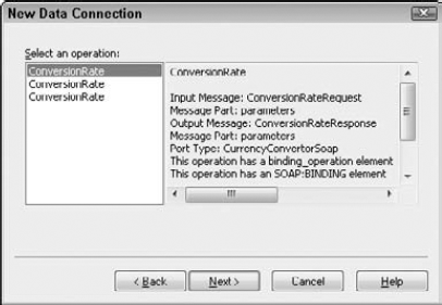
http://www.webservicex.net/CurrencyConvertor.asmx?wsdlSelect the top operation from the Connection Properties and choose Next. The top choice in the three conversion rate operations is the service we can connect to as shown in Figure 31.28. The other two operations did not allow any connections, as indicated by the description when selected. Another indicator that the operation is not a supported type is that the Next button is not active.
No additional properties are needed, so choose Finish. The Web service we are connecting to is a free service and does not require any additional properties to connect to it.
Explore the Data View palette. Expand the data view palette to see the available services.
Drag the four currency convertor objects to the form from the Data View palette. Place the currency convertor fields in the blank area of the LowerSection subform. The four objects are FromCurrency, ToCurrency, ConversionRateResponse, and ConversionRateBtn.
Note
For more information on creating fields from Data Connections see the section "Setting Field Bindings" later in this chapter.
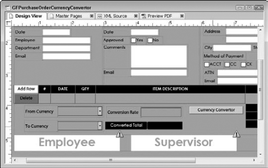
Arrange the fields and adjust the captions as needed. Take a few minutes to arrange the new fields in the available space. Leave enough room for one additional field.
Add a new Numeric Field to the LowerSection Subform and name it ConvertedTotal. We will perform the calculation using the Web service results to alter the existing total to the converted total. Your form should appear similar to Figure 31.29.
Select the ConvertedTotal field and open the script editor. If necessary select Window
Select the Calculate Event from the show drop-down, and set FormCalc as the scripting language. For a simple multiplication problem, FormCalc is shorter syntax to write.
Enter the Calculation to multiply the ConversionRateResult and the Total Field. We entered the following calculation script:
Totals.Row3.Total * ConversionRateResult;
The Script Editor for the ConvertedTotal field should appear similar to Figure 31.30.
Note
For more information on syntax rules and variations available when writing scripts, see Chapter 29.
Save the Form and test it in the Preview PDF tab. Enter some data into the quantity and each fields.
Select a From Currency and To Currency, then click the Currency Convertor button.
Verify the results are correct. Verify the Conversion Rate Response was returned, and the Converted total correctly used the Conversion Rate. Your form should appear similar to Figure 31.31.
Return to Design View and close the form.

As you can see, in many applications Web services can be utilized for form enhancements. Remember that WSDL calls are restricted in the free Adobe Reader unless enabled by LiveCycle Reader Extensions.
Creating the data connection is only part of the process to get fields to display and map properly to the data source. Normal binding is the default setting in Designer and uses implicit binding to work. As we discussed in Chapter 25, implicit binding takes the data file and compares it to the form for exact field name matches. When the data file and the form fields don't match another binding method is necessary.
Note
For more information on Binding types see Chapter 25.
Once a data connection has been established we can bind the fields to the data source. You can bind existing fields to the data source in these two basic ways:
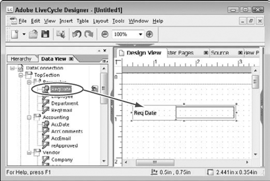
Using the Data View palette. Drag the fields in the Data View palette directly to objects in the design page to create absolute bindings between the data nodes and the form objects. Figure 31.32 shows the Requestor Info Date (ReqDate) field being bound by dragging the element from the Data View palette and dropping it on the field.
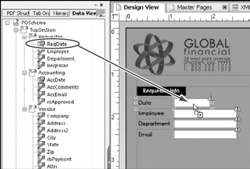
Figure 31.32. Drag and Drop a data element from the Data View palette to a form object to create data bindings.
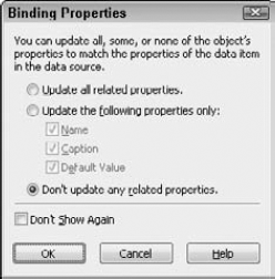
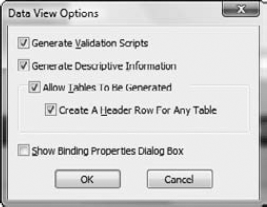
Dragging and dropping an element on the form object opens a properties window to offer additional options. In the case of an XML sample file, the only information available is the name of the field. With a Schema file, additional properties such as field size, data type, caption, and more can be retrieved. Figure 31.33 shows the property window. You may want the same settings for each field in this form; by making the appropriate choices and selecting Don't Show Again, the settings will be retained until you change them. To return to the properties window after it has been hidden, select the Data View palette Menu and choose Options to change your settings as shown in Figure 31.34.
Using the Binding Tab of the Object palette. With the object selected in the form design, open the binding tab of the object palette to select the data node to bind to. Figure 31.35 shows the flyout data binding options when setting the binding for the Employee field using the Object palette.
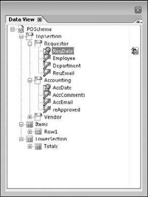
Once a binding has been specified for a field, the Data View palette updates with an icon to show which fields have been bound as shown in Figure 31.36. The red and green arrows indicate import (green) and export (red) data bindings.
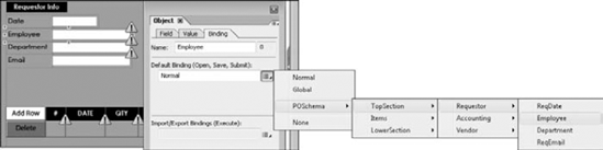
Figure 31.35. The data source structure appears in the binding tab to define a connection between fields and the data source
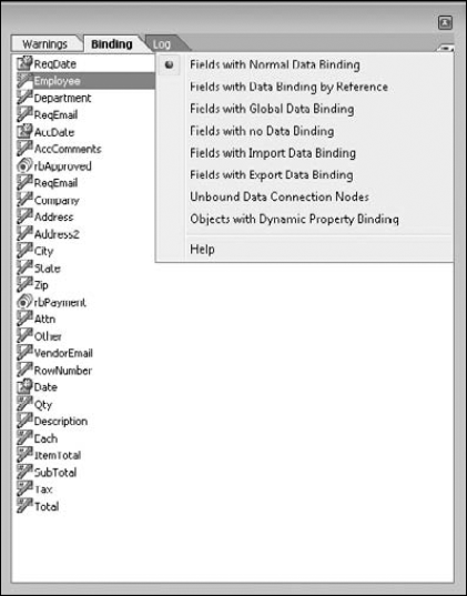
Another other way to check data bindings is to view the Binding tab of the Report palette, and select Window
When binding a field to a data element with the Data View palette or in the Object palette, Designer establishes an explicit binding. With explicit bindings a reference to the data element becomes embedded in the form design and ignores the automatic data matching. An explicit binding can be either relative or absolute. Absolute bindings ensure the exact data element can be found regardless of the object name. We recommend using the drag-and-drop method from the Data View palette as the preferred method.
When binding to a dynamic form with repeating sections, relative binding is generally required to correctly bind the contents. In addition, relative binding expressions require less processing when merging data with a form design. Absolute bindings are not recommended with repeating sections unless the intent is to filter the repeating data. In order to set a relative reference for an existing subform, you will need to use the Binding Tab of the Object palette. Once the subform binding is established, dragging the elements from the Data View palette to the fields inside the subform sets relative bindings.
If the data connection is established at the beginning of the form design process, you can take advantage of the information the data file has when creating your fields. Rather than building each of the field objects and then setting the bindings, you can simply drag the data elements to the design page to create the objects and establish their bindings all in one step as shown in Figure 31.38.
Dragging a complex container from the Data View palette creates the container object and all of the child objects it contains. This can be a huge time-saving feature if you have either a sample XML data file or better yet a Schema file to work with.
Extensible Markup Language (XML) is used for data storage and transfer.
Designer can use a Sample XML data file, XML Schema, OLEDB, or WSDL files to create data bindings.
An XML Schema defines the data set, which can include data types and additional properties.
Database and WSDL connections are restricted in the free Adobe Reader.
The default binding type in Designer is Normal. Normal is implicit binding.
Explicit bindings can be relative or absolute when connected to a data source.
Bindings can be added to existing fields by dragging from the Data View palette or using the Data tab of the Object palette.