
Preselector for a short-wave receiver
The circuit
This is shown in Figure 1. The signal from the aerial arrives at an RF transformer, the secondary of which is tuned with capacitor VC1a. The output from the tuned circuit is taken from a tap on the secondary to the source of the FET. The gate is grounded (earthed) and the amplified signal appears at the FET drain, which is then fed to the primary of another RF transformer, which is tuned by VC1b. The output to the receiver comes from the secondary of the RF transformer.
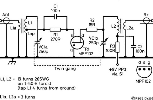
Notice that the two RF transformers are identical, but they are used ‘back to back’, with the secondary of the first and the primary of the second being tuned. They are tuned with identical capacitors, fitted on the same shaft of a variable capacitor. We say that the two capacitors are ‘ganged’. Because L1 and L2 are the same, and VC1a and VC1b are the same, both RF transformers should be resonant at the same frequency, no matter what that frequency is.
Construction
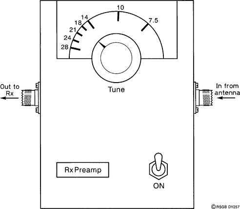
The final layout should look something like that shown in Figure 2. The external connectors and controls being two SO-239 sockets for connection to your receiver and aerial, a tuning control and its associated scale, and an on/off switch.
The circuit can be put together on a plain matrix board, using pins to anchor the components, or simply by pushing the component leads through the board and making connections on the underside. The layout of the prototype is shown in Figure 3. Mounting the board to the aluminium box is accomplished with bolts, solder tags and stand-off insulators.
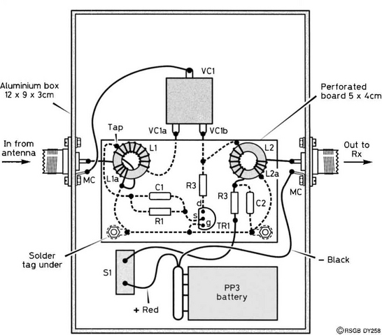
Check your construction against the circuit diagram and against the layout diagram. Wire in the PP3 battery clip, put the switch in the ‘off’ position, and fit the battery. Testing can be carried out without fitting the top of the box.
Testing
Don’t fit your preselector yet. Tune your radio to a broadcast station, preferably a fairly weak one. Disconnect the aerial and fit your preselector between the aerial and receiver. Switch it on and rotate the tuning knob slowly. You should find a position where your original station is received more clearly than before. If it doesn’t work at all, recheck your wiring. Is there a positive voltage on the drain of the FET? If not, work back towards the positive battery terminal. Is there a voltage at the junction of L2 and R2? Is there a voltage at the junction of L2 and R3? Is there a voltage at the junction of R3 and the battery lead? If there isn’t a voltage at that point, then you have probably mounted your switch upside down, and it is off, not on! It’s a common mistake.
Calibration
This is not obligatory, surprisingly enough. However, if having a frequency scale appeals to you, then using an RF signal generator (or using the services of a friend who has one) is the simplest solution. Feed in a weak modulated signal from the generator to the preselector, and rotate VC1 until the signal is maximum. Mark this frequency on your dial. Repeat the process for the frequencies shown on the dial in Figure 2.
If you have a commercial transceiver, feed its output into a dummy load (such as the type described in A Switched Dummy Load, elsewhere in this book) using a distinctive modulating signal such as an idling RTTY signal. Set the receiver to the same frequency with the preselector out of circuit. Insert it into the aerial lead, and search for the signal with VC1 until it gives the maximum deflection on your S-meter, then mark the frequency on your dial.