A CW transmitter for 160 to 20 metres
The circuit
The three-transistor circuit is shown in Figure 1. It comprises a crystal oscillator using a BC182 transistor which drives a 2N3866 power amplifier (PA) keyed by a ZTX750 PNP transistor. The oscillator and PA are coupled by a capacitor and resistor; this provides a very small amount of positive bias to the PA.
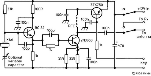
The oscillator can be used as a basic crystal oscillator but, by including a variable series capacitor as shown in Figure 1, the crystal frequency can be ‘pulled’ slightly, making the oscillator a variable crystal oscillator (VXO).
Construction
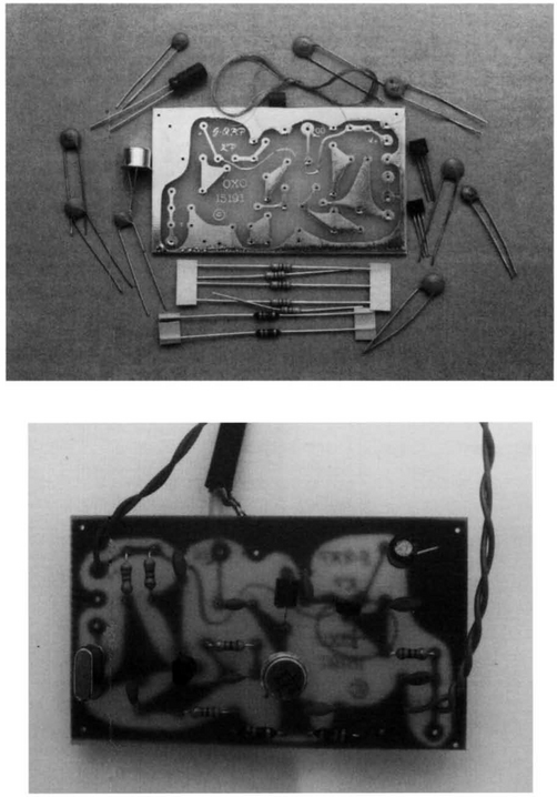
The PCB layout is shown in Figure 2 and in the photograph. Although the prototype was built around a PCB, this circuit is equally amenable to construction on a matrix board. Populating the PCB is very simple, and you can expect to be able to do this in about one hour. The radio-frequency choke (RFC) is made by winding 10 turns of 33 SWG wire on a ferrite bead. The enamel coating of the wire is intended to vaporise when soldered into the board, thus obviating the need to remove the enamel manually with a knife or sandpaper. However, if you do have problems with the PA either not working or keying intermittently, it is suggested that you investigate the RFC connections immediately!

If you decide to make the VXO version, you will have to cut the track between the crystal and earth, and connect the variable capacitor (250 pF) across the break.
In use
After performing the usual checks on the accuracy of your circuit building and the wiring of the external components, it is time to connect a 12 V battery between the points shown in Figure 2. Do not switch on yet. An aerial needs to be connected to the output via an ATU and a crystal, of frequency matching that of the aerial, fitted. The variable capacitor should give you a tuning range from about 14.058 to 14.064 MHz. ‘Netting’ (the process of tuning your transmitter to the same frequency as that of a received station) is achieved simply, because the oscillator is always running, and the leakage of the signal (despite the fact that the PA is not powered) is sufficient to bring the two frequencies to zero beat.