
Simple aerials
VHF aerials
For VHF operation, the aerial should be mounted as high as possible, either on a mast or on a chimney. For all-round coverage on FM and the local repeaters, a vertical colinear is a good choice. For SSB and CW DX operation, a horizontal rotatable beam is needed. If satellite working is envisaged, you will need to contemplate mounting an elevator on top of your rotator, so that your beam can point in any direction, including vertically upwards! An advantage of satellite working is that the aerials do not necessarily have to be up in the air, provided you have a relatively uncluttered site. Your rotator and elevator can be at ground level, which is good!
If the VHF aerial is mounted on the chimney, use a double mounting bracket, particularly if you have a beam and rotator. Keep the TV, broadcast FM and amateur aerials as far apart as possible, and keeping the feeders separated is also a good plan.
The dipole aerial
One of the simplest types of aerial for single-band operation is the half-wave dipole. (The name ‘dipole’ simply means ‘two poles’ or ‘two elements’, and in this case the total length of the dipole is approximately half a wavelength at the operating frequency.) It is usually fed in the centre by coaxial cable as shown in Figure 1. The length of the dipole for the lowest frequency in each band is shown in Table 1. Normally, the length of the aerial will be ‘trimmed’ to be tuned to the centre frequency of the part of the band in which you will operate. This is done using the data in the right-hand column of Table 1. As an example, suppose you wanted your aerial to be resonant at 3.7 MHz. The table gives an overall dipole length of 42.86 m for 3.5 MHz. To resonate the aerial 200 kHz higher, then this length must be shortened by 2 × 0.595 m = 1.190 m. Your dipole would thus be 41.67 m long. Remember to allow extra wire for fixing the dipole ends to the insulators.
Table 1
Dipole lengths for lowest frequency of each band and the length to be trimmed from each to raise the resonant frequency by 100 kHz


On the lower-frequency bands, the lengths become rather large. In this case, you can ‘bend’ your dipole, as illustrated in Figure 2. The length of wire required to give an acceptable value of SWR (less than 2:1 on transmit) may need to be different from the calculated value, so be prepared to experiment!

Dipoles are single-band aerials, although they will often work acceptably on the third harmonic of their design frequency: a 7 MHz dipole often operates reasonably well on 21 MHz. It is possible to operate several dipoles in parallel, as Figure 3 shows. Interaction between the elements can occur if the spacing between them is less than about 10 cm. A multi-band dipole, as shown in Figure 3, has the elements separated with plastic spacers, and drooping ends to produce maximum spacing between the elements’ ends.

The long-wire aerial
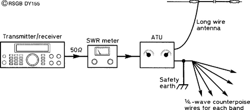
This aerial is simple, cheap, easy to erect, and suits most houses and gardens, as Figure 4 shows. Using an aerial tuning unit (ATU), an end-fed long wire can function on several bands when used with a set of radials or a counterpoise. Figure 5 illustrates the setup. The length of the aerial will determine the bands which will be covered.

A wire length of 10.5 m will work on the 40, 30, 17, 15 and 12 m bands.
A wire length of 15.5 m will work (with an ATU) on the 80, 40, 20 and 12 m bands and possibly (depending on your ATU) on the 17 and 15 m bands.
A wire length of 26.5 m will operate on all bands, but may be difficult to load on 10 m.
The wire lengths given here may need some adjustment because of the geometry of your particular house and garden. For receive-only purposes, the lengths are far less critical.
In general, you cannot get a good radio-frequency (RF) earth from a first-floor (or higher) shack. Unless a good RF earth exists within a small fraction of a wavelength of the transceiver, an artificial ground comprising a single ![]() radial or counterpoise will be needed. You will need one counterpoise for each band you intend to use, and the wire can be concealed around the skirting-board of the shack, or under the carpet. Make sure that the free end of each counterpoise is well insulated; this point can carry a very high voltage when you transmit; anyone coming into contact with this can suffer very severe RF burns. Counterpoise lengths can be read from Table 2.
radial or counterpoise will be needed. You will need one counterpoise for each band you intend to use, and the wire can be concealed around the skirting-board of the shack, or under the carpet. Make sure that the free end of each counterpoise is well insulated; this point can carry a very high voltage when you transmit; anyone coming into contact with this can suffer very severe RF burns. Counterpoise lengths can be read from Table 2.

The vertical aerial
The single-band vertical aerial is sometimes used by DX operators because it has a low angle of radiation, which favours long-distance propagation. However, it must be sited clear of obstructions and must have a good counterpoise or radial system. Illustrations of the vertical aerial are shown, and the lengths of the vertical and radial sections are given in Table 2. The centre of the coaxial feeder is connected to the vertical section, and the braid to the counterpoise or radial system, which is made up of four or more wires buried just below the surface and joined together near the base of the aerial.
Cable entry to the house
Bringing coaxial cable into the house by an open window must be regarded as a temporary measure. Wooden window frames can be drilled, one hole for each feeder. Make the holes slope downwards from inside to out to prevent rain entering, and treat these with wood preservative. Leads from long-wire and inverted-L aerials should be kept separate from other cables.
Alternatively, a plastic pipe large enough to take all your feeders could be fitted into the brickwork (again, sloping downwards towards the outside). You may want to let a friendly builder do this for you.