
A 7-element low-pass filter for transmitters
A design of 7-element low-pass filter
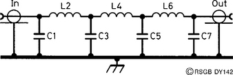
A 7-elemcnt low-pass filter (LPF) is so called because it has seven components, as the circuit diagram of Figure 1 shows. Filters containing any odd number of elements are possible: a 3-element filter would comprise C1, L2 and C3 only, and is sometimes called a pi-network because the element disposition resembles the Greek letter pi (π); a 5-element filter would comprise C1, L2, C3, L4 and C5 only, and so on. In general, the more elements the filter has, the more effectively it attenuates signals above f.
The circuit of Figure 1 is designed to have an input and an output impedance of 50 Ω, which means that it can be placed in the aerial feed of any common transmitter. Filter design is a very complex business, and is best left to the experts. One such expert is W3NQN, who produced a number of computer designs of LPF using commonly available (preferred value) capacitors, and aimed specifically for use on amateur frequencies. The results of this work are condensed into Table 1. The inductors are wound on standard toroidal cores, and their details are included in the table.

Making the filter
The filter was made originally as an adjunct to the Breadboard 80 m CW transmitter, which you will also find in this book. It uses the same constructional technique, based on a single piece of plain, copper-clad PCB, with ‘pads’ created by using a sharp blade in a junior hacksaw. The cuts in the copper are shown in the layout diagram of Figure 2. There are two ways of mounting the components: the first way is to drill small holes in each pad, as shown in Figure 2, and mount the components through the holes in the normal PCB manner; the second way is to solder the components directly to the pads, in the way that was described for the Breadboard transmitter.

Winding the inductors is quite simple. All you need to remember is that each time the wire passes through the core counts as one turn. Cut off the spare wire at each end of each coil to about 1 cm, scrape off the enamel with sandpaper, and tin the exposed copper. See the transmitter description if you are unsure of how to do this. Note the wire links between each of the lower pads, forming a solid ‘ground’ for the elements. The prototype had a plug and socket on the ends, to match the transmitter and aerial terminations.
The type of capacitor used in the design is not critical; the polystyrene type works well.