
A charger for NiCad batteries
Charging NiCads – the ampère-hour
NiCads require charging at constant current, which means that connecting one across a normal power supply (constant voltage) is useless and can destroy it. They need pampering to the extent of needing a long charge (around 16 hours) at a rate dependent upon the capacity of the battery. By the capacity of a battery, we mean how much energy it can store. You will probably know that energy is measured in joules. For the purposes of storing energy in batteries, the joule is not the ideal unit, so we use one that is! This unit is the ampère-hour (Ah), and must be interpreted with some realism. For example, if the battery is rated at 2 Ah, it will deliver a current of 0.5 amp for 4 hours, or 0.25 amp for 8 hours. Provided the current is not too high, the product of the current (in amps) and the time for which it will flow (in hours) before the battery is flat will always be around 2 Ah. A workable ‘rule of thumb’ for calculating the charging current is that its value should be around one-tenth of the numerical value of the capacity; so, for our 2 Ah battery, a charging current of around 200 mA (2 ÷ 10 = 0.2 A or 200 mA) would be used.
Constant voltage to constant current
Many integrated circuit (IC) chips are available for use as voltage regulators, i.e. they supply a constant voltage. Most of these can be persuaded to become constant current supplies with one external resistor!
The voltage regulator IC usually has only three connections – ‘input’, ‘output’ and ‘common’. It is designed (in the case of the LM7805) to produce a constant 5 V output between the ‘output’ and the ‘common’ connections, at currents of up to 1 A. If a resistor is connected between these, the IC will maintain 5 V across it. If you look at Figure 1, you will see the circuit performing this conversion.

For the previous example, we derived a charging current of 200 mA, so we now need to calculate the value of resistor that will produce this current. Using the equation which is derived from Ohm’s law:
where
25 ohms is not a ‘common’ or ‘preferred’ resistor value, so we must choose the next largest value, which is 27 Ω. This reduces the current, but only slightly – it is now 185 mA. When calculating resistor values in power supply circuits, we must always check the power that they dissipate and make sure we specify and fit a suitable resistor.
Power (in watts) is the product of the voltage across and the current through a device, so in this case it is given by:
Rather than use a 1 watt resistor operating very near its limit, it is safer to use a 2 watt resistor operating well within its limits.
Looking again at Figure 1, we now have a constant-current source producing 185 mA, when R1 is a 27 Ω, 2 W resistor. For use with NiCads requiring charging currents other than 200 mA, you will need to repeat the two equations above, using a new value for I.
The full circuit and its assembly
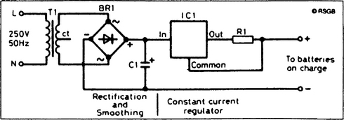
This is shown in Figure 2, and can be broken down into two parts. The first is the AC to DC conversion produced by the mains transformer, T1, the bridge rectifier, BR1, and the smoothing capacitor, C1. The second is the constant-current section already discussed.
The prototype was assembled on matrix board measuring 18 holes by 12 strips, although, as Figure 3 shows, this is much larger than is strictly necessary. No strip cutting is needed, but make sure that IC1 and C1 are inserted correctly.

Warning! Before you attempt to wire up the transformer and the bridge rectifier, be aware that you will eventually be connecting the circuit to the mains supply, so there are three possibilities for you: (1) get a qualified friend to supervise your completion and testing of the circuit; (2) get your qualified friend to complete and test the circuit for you; (3) replace the transformer and bridge rectifier with a mains adapter.
If you decide to use the mains adapter, its output is connected directly across C1, because T1 and BR1 are now no longer needed. Make sure the polarity (positive and negative) is correct and that the adapter output is set to 12 V.
A quick test
If you have built the mains version, make sure all connections are correct, and that there are no soldered joints which will touch other parts of the circuit. The box must be securely closed before tests begin. The RSGB cannot be held responsible for damage to equipment or batteries! The version using the mains adapter need not be closed during tests.
Switch on. With nothing connected to the output, the unit should run cold. If this is not the case, switch off and recheck your circuit. If all is well, switch on again and connect a DC multimeter (on the current range) across the output. It should indicate only a slight difference from the calculated value of 185 mA. You can now charge your NiCads!
Other charging currents can be set by having different values for R1, perhaps selectable by a rotary switch. Remember to make sure that the values of both resistance and power dissipation are correct, and don’t exceed the 250 mA rating of the transformer (or the 1 amp rating of the IC if you are using a bigger transformer).