A 1750 Hz toneburst for repeater access
Warning
This circuit uses a member of the integrated circuit family known as CMOS (complementary metal-oxide semiconductor). These use very little current and can be completed destroyed if they come into contact with the magnitudes of static electricity that most of us carry about when we walk on carpets and wear rubber shoes. You will never know if this wanton destruction has happened – all you will discover is that your circuit doesn’t work and that you have tested everything. To avoid this problem do the following things:
1. Before you open the little packet in which the IC is supplied, touch something which you know to be earthed – the metalwork of any equipment which is mains earthed, for example. Then open the packet.
2. Let the IC fall gently on the bench – don’t pick it out with your fingers. Touch your earthed metalwork again. Pick up the IC and insert it gently into its holder.
The circuit is safe from destruction while it is connected to the battery.
Circuit description
The circuit is shown in Figure 1. The tone is generated by an integrated circuit oscillator (IC1), whose frequency is controlled by a ceramic resonator, XL1. Its frequency is very high, and is divided down to the 1750 Hz needed by the same chip. The ceramic resonator is designed to operate at 455 kHz, the intermediate frequency of many receivers. Because all divider circuits use powers of 2, we need the oscillator to run at 448 kHz so that when it is divided by 256 (256 = 28), we end up with 1750 Hz. Try it on your calculator:
We use C1, C2 and R1 to pull the frequency of the oscillator away from 455 kHz to 448 kHz. The divider chain has eight counters in it, and each counter divides the frequency of the signal it sees by two, giving the final division of 256.

This counting process can be stopped at any time by taking the voltage on the reset pin (pin 12) up to the supply voltage. When the circuit is switched on by closing S1, pin 12 is at 0 V because C3 is discharged. The oscillator runs, producing the output frequency of 1750 Hz. As time progresses, C3 charges up through R2 and the voltage on pin 12 rises. When this has risen sufficiently, and in a time determined by the values of C3 and R2, the counter resets and stays in the reset state; no division takes place and there is no output. The duration of the toneburst is thus governed by C3 and R2.
When S1 is opened, the circuit is switched off, and C3 is discharged through D1 and R3, ready for the next toneburst. If you have used a repeater, you will know that a toneburst is needed only to activate a repeater in the standby condition; it is not needed once a contact has been established.
VR1 adjusts the amplitude of the tone fed to the microphone, and C4 prevents any voltage that may be present on your microphone connector from damaging the integrated circuit.
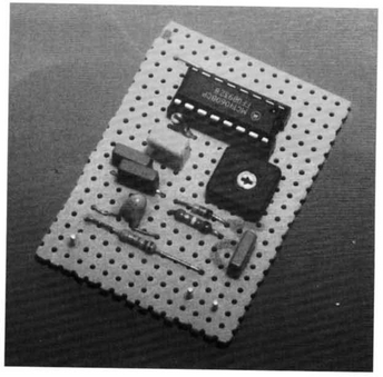
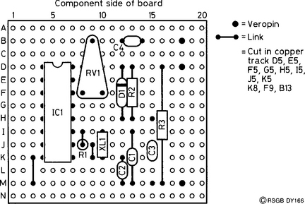
Construction
The prototype circuit was built on Veroboard of the copper-strip variety, measuring 20 holes by 14 strips. The layout is shown in Figure 2. Make the track cuts first, and check that there are no slivers of copper wedged between adjacent tracks. Then, solder in the IC socket (with the notched end facing towards track A), the wire links and the three Veropins. Having done this, solder in the resistors, capacitors and diode, making sure that D1 and C3 are the right way round! Using your best soldering technique, solder in the ceramic resonator quickly, to prevent heat damage. Recheck your circuit, check for solder splashes and bridges, and then gently insert IC1 into its socket, matching up its notch with that of the socket.
Testing
Set VR1 to half-way and connect a crystal earpiece to the output; apply power to the circuit. You should hear the tone, lasting for about half a second. If there is no tone, disconnect your circuit from the power supply, and check for dry joints in the vicinity of pin 12. Is the diode, D1, the correct way round? Is C3 the correct way round? Did you choose to ignore the CMOS safety precautions given earlier?
Once the circuit is working, you need to decide how you are going to connect it to your transmitter. Two options are shown in Figure 3. If you have access to a point in your transmitter circuit that has between 9 V and 12 V positive on it during transmit, you can use this to power your circuit. As the toneburst is needed only for repeaters, the switch, S1, disconnects it when not needed, as shown in Figure 3a. If you want the circuit to be self-powered, then a 9 volt PP3 battery may be used; Figure 3b shows this configuration.

The output from the circuit board is fed directly into the microphone socket, in parallel with the microphone itself; use thin coaxial or screened cable for this lead, or you may induce hum into the microphone circuit and suffer from RF breakthrough into the audio circuits. To adjust the setting of VR1, start with it at the zero output position and connect a dummy load to your transmitter. Slowly, increase the output while monitoring your transmitted signal on another nearby receiver. Make sure you do not increase the output so far that the signal sounds distorted. If you would prefer that the tone was on continuously while you made this adjustment, simply connect a wire across C3 remembering, of course, to remove it as soon as you have completed the test!