
Water level alarm
Detecting water
Water is not too difficult to detect electrically, because it is a conductor of electricity. Not a good one, but sufficiently so to carry enough current to control a warning circuit.
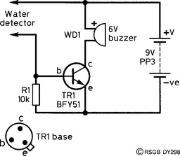
The circuit is shown in Figure 1. If you imagine a resistor placed between the ends marked ‘water detector’, the circuit is then recognisable as a transistor used as an electronic switch. Whether the switch is off or on depends on the value of this resistor. If the resistance is low, the transistor switches on and the buzzer sounds. If the resistance is high, the transistor switches off and the buzzer stops.
Construction
The unit is made in two separate sections – the detector board (Figure 2) and the main board (Figure 3). The main board is plain perforated board (without copper strips). The components are pushed through holes in the main board and connected together on the underside. The battery is held on with sticky tape. No on/off switch is used, as the circuit consumes virtually no current when it is not sounding the buzzer.

Unlike some buzzers, this type is polarised, and the red lead must go to the supply as shown in Figs 1 and 3.
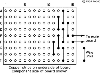
The detector board is a piece of standard matrix board – the type with copper strips along one side. It measures 9 strips by 15 holes, and is wired in such a way that alternate strips are connected together, as Figure 2 shows. This gives a greater surface area for the water to touch, thus increasing the sensitivity of detection.
The two boards are connected by ordinary twisted pair, enabling the detector to hang over the edge of the water container, with the buzzer circuit safely out of the way. When positioning the detector board, the left-hand edge (as shown in Figure 2) should face downwards, with the connecting-wire edge facing upwards. When the water level rises, the water causes current to flow between adjacent strips, and the higher the water, the lower the resistance between them. Eventually, the resistance will be low enough to turn on the transistor and sound the alarm.