
A simple electronic organ
This project has nothing to do with radio but, let’s admit it, any electronics project is good experience! Why not build this little organ – it will keep the children amused at least! It uses the popular NE555 integrated circuit, which contains a circuit which will periodically switch the voltage on the output pin between the supply voltage and zero. Just how frequently this switching occurs depends upon the components external to the integrated circuit. If this switching occurs several hundred or thousand times a second, the change in voltage produced will generate a musical note when connected to a small loudspeaker. The circuit is shown in Figure 1.

Putting it together
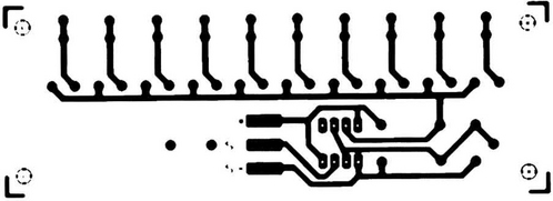
(a) Using a PCB. The job is very simple. The placement of components on the unsoldered side of the board is shown in Figure 2 and the design on the copper track is illustrated in Figure 3. Put each component, in turn, on the board, making sure that it lies flat on the board with its tags or wires going cleanly through the holes provided for it; then, solder the wires to the board, cropping them before or after the soldering, depending on your preference. If you choose to use a holder for your integrated circuit (highly recommended if your soldering is less than perfect), make sure that the end with a notch in it faces R1 and R2, as shown in Figure 2. Solder the two leads to the speaker to the tabs marked S (either way round), having looped them through the two holes to the right of the tabs in Figure 2. Looping them through the holes acts as a strain relief, ensuring that the soldered joints are not subjected to pulling and bending as you move the wires about. Do the same with the battery leads, the red lead going to the + tab and the negative lead to the – tab (which also has one speaker lead already attached to it). Figure 4 shows this in detail. Treat the loudspeaker with care – the cone is quite fragile and must not be touched.


(b) Without a PCB. This is more difficult, and you may need to enlist some help. Using some matrix board (such as Veroboard) is probably the best way of replacing the PCB. You could arrange your circuit in exactly the same way as in the PCB in Figure 3, using wires to replace the copper track.
A simple ‘keyboard’
The keyboard is a row of solder pins along the rear edge of the PCB, one for each note covering the range shown in Figure 2. A flying lead with a small spade on it is provided to touch any of the pins in turn, producing any one of ten different notes.
Testing
Check first that each component is in the correct place. When inserting the NE555 chip, first make sure that the end carrying the notch lies over the end of the holder with the notch; then, make sure each pin of the chip lies directly above the hole into which it fits, before pressing gently to insert the chip into the socket. Make sure the battery connections are correct, and insert the battery into the clip. Nothing should happen, except for a click from the loudspeaker; touching the spade on any of the pins should produce a coarse note from the speaker. If nothing happens, check everything again; don’t assume that wires go where you think they go!
After you get the first note, all the others should work, too, but they will sound off-tune at first. The organ needs tuning up by adjusting the 10 preset variable resistors P1 to P10. The approximate frequency to which each note should be tuned is given in Figure 2; if you can beg, borrow or steal a frequency counter, setting up is easy. If you have a piano, the organ can be tuned by comparison of the notes with those on the piano. The frequencies are given in Hertz (abbreviation Hz), and represent the number of times the IC switches on and off every second. If the sound coming from the loudspeaker is too loud or very distorted, then try putting an 330 Ω resistor (colour code orange, orange, brown) in series with the loudspeaker. This is done by taking the resistor and cutting its leads to about 5 mm; then, disconnect one speaker lead from the tab on the PCB (it doesn’t matter which). Solder one end of the resistor to the vacated speaker tab, and the free speaker lead to the other end of the resistor. This will limit the volume of sound from the speaker, and lengthen the life of your battery. If it is still too loud, try a resistor of a larger value, or use a smaller resistor to make it louder.