
Christmas tree LEDs
Warning
This circuit uses members of the integrated circuit family known as CMOS (complementary metal-oxide semiconductor). These use very little current and can be completed destroyed if they come into contact with the magnitudes of static electricity that most of us carry about when we walk on carpets and wear rubber shoes. You will never know if this wanton destruction has happened – all you will discover is that your circuit doesn’t work and that you have tested everything. To avoid this problem do the following things:
1. Before you open the little packet in which each IC is supplied, touch something which you know to be earthed – the metalwork of any equipment which is mains-earthed, for example. Then open the packet.
2. Let the IC fall gently on the bench – don’t pick it out with your fingers. Touch your earthed metalwork again. Pick up the IC and insert it gently into its holder.
The circuit is safe from destruction while it is connected to the battery. However, when the battery is removed, the same care should be exercised with its handling, because there are no supply decoupling capacitors across each IC.
Description
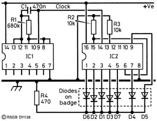
Figure 1 shows the layout, and how the wires are connected from the circuit board to the LEDs around the tree. The circuit, shown in Figure 2, is quite complicated, so you need to be confident in your logical approach to circuit-building before you attempt this one! It uses two common integrated circuits (ICs). IC1 is simply an oscillator which provides timing pulses for IC2, which ‘counts’ up to a maximum of 10. The outputs of the counter are indicated by light-emitting diodes (LEDs); red, orange, yellow and green are common colours which you can use.
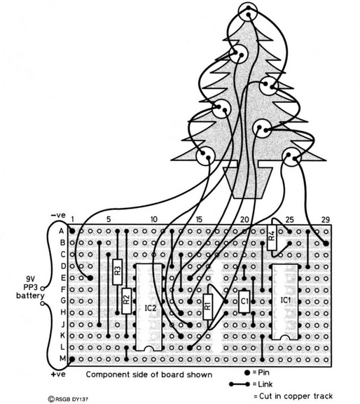
The circuit is built on a single piece of Veroboard measuring 29 holes by 12 strips. Be aware that there is no strip labelled ‘I’, so don’t make mistakes in your counting!
First of all, cut the tracks in the positions shown in Figure 1 using a 3 mm (⅛ inch) twist drill rotated between thumb and forefinger. Then, solder in the IC sockets, the notches facing row M. Wire up and solder in the links and then the Veropins for the connections to the LEDs and battery. Having done this, the resistors and the capacitor should be fitted. When wiring the LEDs, each cathode (the lead adjacent to the ‘flat’ on the LED encapsulation) is connected to R4, and the anodes go to separate pins on IC2.
Testing
Hold up your circuit board to the light and check carefully for solder bridges between adjacent tracks. Then check again that the wiring is correct. Place the ICs in their holders, with the notched ends lining up with those on the holders. Connect the battery, and the LEDs should illuminate in sequence.
If you have no success, you are now wishing you had checked the circuit more carefully! Learn something from your mistake and it will not have been in vain! The first thing to check is that the LEDs are the correct way round. If that is OK, then check the positions where the tracks are broken (intentionally!). After that, are the wire links in the right places – had you forgotten there is no row ‘I’? Check all the wiring, then check again for solder bridges, and switch on again. One of these tests should have revealed a fault. If it still refuses to work, perhaps one (or both) of your ICs were damaged by static electricity, despite your precautions – or did you choose to ignore them?