
An HF absorption wavemeter
The circuit
Figure 1 shows the circuit of the wavemeter. It is designed to cover all the HF bands from 1.8 MHz to 28 MHz in four switchable ranges. There is no built-in method of amplification, so a sensitive meter is needed in order to indicate sufficiently using the available absorbed energy. The meter does not need calibrating, it serves to produce only an indication of the absorbed power, not its absolute value.
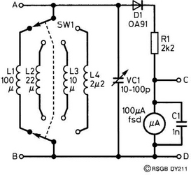
An absorption wavemeter does not have outstanding selectivity, mainly because of the loading effect of the meter. This problem is ameliorated here (but only slightly) by the inclusion of R1 in series with the meter. It gives improved selectivity at the expense of a slight loss of sensitivity. The appearance of capacitor C1 across the meter is discussed in The Absorption Wavemeter, in the previous section.
Coils
These can be purchased (see the parts list) or hand-wound on short lengths of PVC water pipe or conduit, and the coil-winding details are given in Table 1. In theory, the 100 pF tuning capacitor would cover all the HF bands with only three coils, omitting the 22 μH coil. Sample calculations are explained in the previous article. However, its inclusion avoids the common problem of having some bands cramped at the extreme edges of the tuning scales.

Construction
Hand-wound coils, using 19–25 mm PVC formers, have single-layer windings, with their ends secured by threading the wires through two small holes drilled in the formers at each end of each winding.
You may have wondered about the use of the two-pole switch SW1, as all the lower ends of the coils are grounded anyway. The answer lies in the ease of construction. Each coil can be mounted on the tags of the switch for support. If you are using the commercial coils, they are small enough to be accommodated on a miniature rotary switch; a larger rotary switch is required for hand-wound coils. The specification of a 6-way switch allows for the addition of extra frequency ranges at little extra cost. Rotary switches such as the 2-pole, 6-way variety have an adjustable end-stop which allows the number of ways to be set anywhere between 2-ways and 6-ways. Remove the nuts from the switch, and a ‘washer’ will fall out. It is not a washer, really, and has a little piece of metal bent over at right angles to the washer. This fits into one of 12 holes in the body of the switch, and prevents the shaft from turning through 360° and selecting the number of ways.
Calibration
This process needs a commercial amateur-bands transceiver, if it is to be done quickly and accurately.
• Connect the transceiver to a dummy load, and connect a piece of flexible wire from point A in Figure 1 and wrap two or three turns around the cable between the transceiver and the dummy load.
• Turn the transceiver power level control to minimum, and set the frequency at 1.81 MHz and the mode to FM or AM. Switch to transmit.
• With the wavemeter set to its lowest frequency range (i.e. 1.8–3.5 MHz), rotate the tuning capacitor until maximum deflection is obtained from the meter needle. Write the frequency on the inner ring of the wavemeter scale at that point.
• Switch off and retune the transmitter to 3.5 MHz. Repeat the above process.
• Repeat, using switch range 2 for 3.5, 7 and 10 MHz, range 3 for 7, 10 and 14 MHz, and range 4 for 14, 18, 21, 24 and 28 MHz.
An alternative source of calibration signal could be an HF signal generator, with a single-turn loop of wire at the remote end of its cable, and the wire from the wavemeter brought close to the loop.
Remember that the marks on the scale represent frequency bands, not precise frequencies.
Extending the range
If you would like to experiment with increasing the range to the lower VHF band, then 50 MHz should be achievable with an additional self-supporting coil (no former). Try three turns of 20 SWG enamelled copper wire of 25 mm ID (internal diameter). Wind it on some 25 mm PVC pipe, as before, then slide out the pipe! The same result could be achieved with four turns of 19 or 20 mm ID, or 12 turns of 7.1 mm ID.