
A simple desk microphone
Construction
The end caps and the ink tubes should be removed from two ball-point pens, leaving only the two plastic shells. One of them is used for the vertical microphone support, while the other is used to hold the microphone element.
The vertical support should have the pointed end shaped so that it holds the microphone support at a convenient angle, as Figure 1 shows.

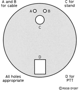
The base should be prepared next – see Figure 2. Four holes are required. Two, A and B, are small holes for the cable to be fed through. A third, C, is slightly larger and is used to take one of the plastic end caps. The fourth hole, D, is determined by the type of switch that you want to use for the PTT function.
Some epoxy resin such as Araldite Rapid is used to mount the separate parts. Mix only a small amount at a time, and glue each part of the base assembly and allow to harden before moving on. Be sure to read and follow the instructions for the use of the glue to prevent accidents.
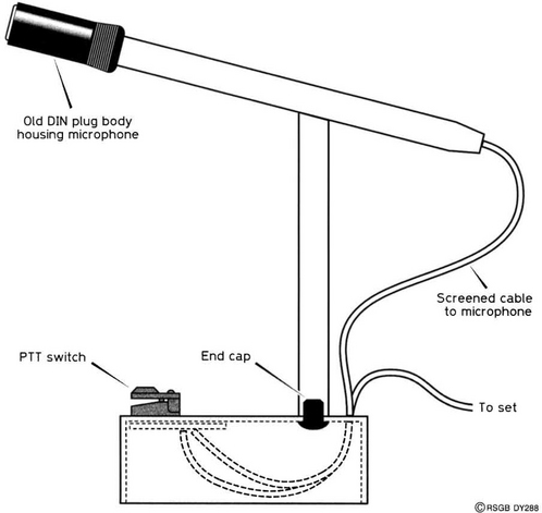
Firstly, glue the end cap to the base, feeding it underneath and pushing it up through hole C. Then, the vertical pen body is placed over the protruding end cap and glued into place, making sure that the top (shaped) end is pointing in the right direction to hold the other plastic tube carrying the microphone. While the glue hardens, place the DIN plug sheath on the second pen body. Place and glue this pen body on the shaped top of the vertical support, making sure that the whole assembly is supported while the glue sets. What you should have now ought to resemble Figure 3, but without the microphone and wiring. Leave everything to set for 24 hours.
Any switch of the press-to-make variety can be used for your PTT switch, but choose one which does not apply too much force to operate! If you find the whole assembly is too light and slides over your table, some plasticine can be pushed into the base when all the wiring has been completed.
The circuit
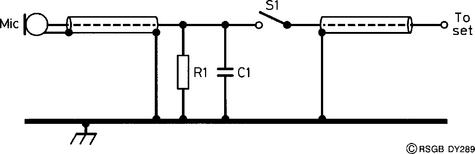
A small electret condenser microphone is used, powered by a DC supply. Most hand-held radios use a single screened lead for both the PTT line and the microphone audio lead. In such cases, the circuit of Figure 4 will operate the PTT function. Note that the PTT switch is in series with the audio lead from the microphone. If you find that the PTT switch does not switch your radio into transmit, reduce R1 from its normal value of 33 kΩ to 27 kΩ. You should find that the original value works with most hand-helds.
For radios with a separate PTT lead, the circuit of Figure 5 is used. However, a power supply is needed for the electret microphone. This can be a PP3 battery, or can (in most cases) be derived from the microphone socket on the transceiver. You will need to consult the makers’ handbook for this information. Figure 5 shows the PTT switch wired in a ‘ground-to-transmit’ configuration, which is correct for most base-station transceivers. If you’re in any doubt about what your radio needs, consult an experienced friend.

The last connections
The microphone element should be connected with screened cable. Tape (masking or insulating) should be wound around the electret insert until it is a snug fit inside the DIN plug sheath. Feed the screened cable through the barrel of the pen until it emerges from the far end. Poke it through hole B and make the connections under the coffee jar lid. The components can all be mounted on the PTT switch or on a small piece of Veroboard mounted under the top surface. The output lead emerges through hole A and is of sufficient length to reach your transceiver. A suitable plug needs to be fitted to it.